Page 2722 of 4171
DOOR MIRRORMIR-15
< DISASSEMBLY AND ASSEMBLY >
C
DE
F
G H
I
J
K
M A
B
MIR
N
O P
3. Disconnect the connector (A) and remove the actuator (1).
Assembly
Assembly is the reverse order of disassembly.
DOOR MIRROR COVER
DOOR MIRROR COVER : DisassemblyINFOID:0000000005890826
1. Using a suitable tool disengage the 4 mirror cover pawls.
CAUTION:
Be careful not to damage the mi rror or mirror cover with tool.
2. Using a suitable tool disengage the 4 mirror cover pawls and remove mirror cover.
DOOR MIRROR COVER : AssemblyINFOID:0000000005890827
Installation is in the reverse order of removal.
CAUTION:
After installation, check that pawls are securely engaged.
ALIIA0318GB
Pawl
ALIIA0396ZZ
Revision: December 20092009 QX56
Page 2724 of 4171

MWI-2
INFORMATION DISPLAY .........................................19
INFORMATION DISPLAY : System Diagram .........20
INFORMATION DISPLAY : System Description ....20
INFORMATION DISPLAY : Component Parts Lo-
cation ................................................................... ...
21
INFORMATION DISPLAY : Component Descrip-
tion ....................................................................... ...
21
COMPASS .........................................................22
Description (Early Production) ............................. ...22
DIAGNOSIS SYSTEM (METER) .......................24
Diagnosis Description .......................................... ...24
CONSULT-III Function (METER/M&A) ................ ...25
COMPONENT DIAGNOSIS ........................28
DTC U1000 CAN COMMUNICATION ............ ...28
DTC Logic ............................................................ ...28
Diagnosis Procedure .............................................28
DTC B2205 VEHICLE SPEED CIRCUIT ...........29
Description ........................................................... ...29
DTC Logic ...............................................................29
Diagnosis Procedure .............................................29
POWER SUPPLY AND GROUND CIRCUIT .....30
COMBINATION METER ........................................ ...30
COMBINATION METER : Diagnosis Procedure ....30
BCM (BODY CONTROL MODULE) ...................... ...30
BCM (BODY CONTROL MODULE) : Diagnosis
Procedure ...............................................................
31
IPDM E/R (INTELLIGENT POWER DISTRIBU-
TION MODULE ENGINE ROOM) .......................... ...
31
IPDM E/R (INTELLIGENT POWER DISTRIBU-
TION MODULE ENGINE ROOM) : Diagnosis Pro-
cedure .....................................................................
31
FUEL LEVEL SENSOR SIGNAL CIRCUIT .......33
Description ........................................................... ...33
Component Function Check ...................................33
Diagnosis Procedure .............................................33
Component Inspection ............................................34
OIL PRESSURE SWITCH SIGNAL CIRCUIT ...35
Description ..............................................................35
Component Function Check ...................................35
Diagnosis Procedure ..............................................35
Component Inspection ............................................35
PARKING BRAKE SWITCH SIGNAL CIR-
CUIT ...................................................................
36
Description ........................................................... ...36
Component Function Check ...................................36
Diagnosis Procedure ..............................................36
Component Inspection ............................................36
WASHER LEVEL SWITCH SIGNAL CIRCUIT ...37
Description ........................................................... ...37
Diagnosis Procedure ............................................ ...37
Component Inspection ............................................37
COMPASS .........................................................38
Wiring Diagram (Early Production) ...................... ...38
CLOCK ..............................................................40
Wiring Diagram .................................................... ...40
ECU DIAGNOSIS .......................................42
COMBINATION METER ................................. ...42
Reference Value .................................................. ...42
Wiring Diagram .......................................................44
Fail Safe ..................................................................61
DTC Index ...............................................................62
BCM (BODY CONTROL MODULE) ..................64
Reference Value .................................................. ...64
Terminal Layout ......................................................66
Physical Values .......................................................66
Wiring Diagram .......................................................72
Fail Safe .................................................................76
DTC Inspection Priority Chart ...............................77
DTC Index ..............................................................77
IPDM E/R (INTELLIGENT POWER DISTRI-
BUTION MODULE ENGINE ROOM) .................
79
Reference Value .................................................. ...79
Terminal Layout ......................................................81
Physical Values .......................................................81
Wiring Diagram .......................................................86
Fail Safe .................................................................89
DTC Index ..............................................................91
SYMPTOM DIAGNOSIS ............................92
THE FUEL GAUGE POINTER DOES NOT
MOVE .............................................................. ...
92
Description ........................................................... ...92
Diagnosis Procedure ...............................................92
THE FUEL GAUGE POINTER DOES NOT
MOVE TO "F" WHEN REFUELING ..................
93
Description ........................................................... ...93
Diagnosis Procedure ...............................................93
THE OIL PRESSURE WARNING LAMP
DOES NOT TURN ON .................................... ...
94
Description ........................................................... ...94
Diagnosis Procedure ...............................................94
THE OIL PRESSURE WARNING LAMP
DOES NOT TURN OFF .................................. ...
95
Description ........................................................... ...95
Diagnosis Procedure ...............................................95
THE PARKING BRAKE RELEASE WARNING
CONTINUES DISPLAYING, OR DOES NOT
DISPLAY ............................................................
96
Description ........................................................... ...96
Revision: December 20092009 QX56
Page 2730 of 4171

MWI-8
< FUNCTION DIAGNOSIS >
METER SYSTEM
SPEEDOMETER
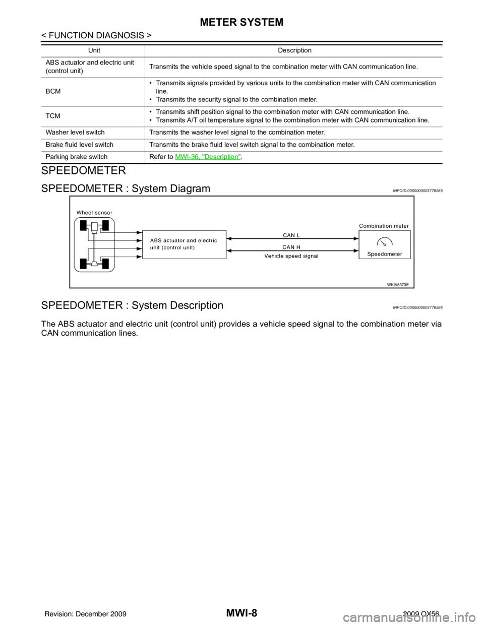
SPEEDOMETER : System DiagramINFOID:0000000003776585
SPEEDOMETER : System DescriptionINFOID:0000000003776586
The ABS actuator and electric unit (control unit) provides a vehicle speed signal to the combination meter via
CAN communication lines.
ABS actuator and electric unit
(control unit) Transmits the vehicle speed signal to the combination meter with CAN communication line.
BCM • Transmits signals provided by various units to the combination meter with CAN communication
line.
• Transmits the security signal to the combination meter.
TCM • Transmits shift position signal to the combination meter with CAN communication line.
• Transmits A/T oil temperature signal to the combination meter with CAN communication line.
Washer level switch Transmits the washer level signal to the combination meter.
Brake fluid level switch Transmits the brake fluid level switch signal to the combination meter.
Parking brake switch Refer to MWI-36, "
Description".
Unit
Description
WKIA5370E
Revision: December 20092009 QX56
Page 2764 of 4171

MWI-42
< ECU DIAGNOSIS >
COMBINATION METER
ECU DIAGNOSIS
COMBINATION METER
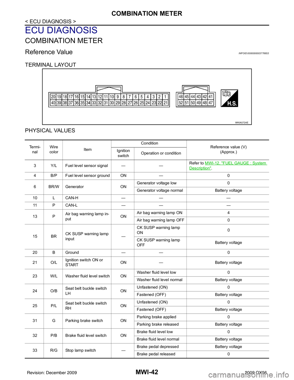
Reference ValueINFOID:0000000003776653
TERMINAL LAYOUT
PHYSICAL VALUES
WKIA5724E
Te r m i -nal Wire
color Item Condition
Reference value (V)
(Approx.)
Ignition
switch Operation or condition
3 Y/L Fuel level sensor signal — —Refer to MWI-12, "
FUEL GAUGE : System
Description".
4 B/P Fuel level sensor ground ON —0
6 BR/W Generator ONGenerator voltage low
0
Generator voltage normal Battery voltage
10 L CAN-H —— —
11 P C A N - L —— —
13 P Air bag warning lamp in-
put ONAir bag warning lamp ON
4
Air bag warning lamp OFF 0
15 BR CK SUSP warning lamp
input —CK SUSP warning lamp
ON
0
CK SUSP warning lamp
OFF Battery voltage
20 B Ground —— 0
21 O/L Ignition switch ON or
START ON
— Battery voltage
23 W/L Washer fluid level switch ON Washer fluid level low
0
Washer fluid level normal Battery voltage
24 O/B Seat belt buckle switch
LH ONUnfastened (ON)
0
Fastened (OFF) Battery voltage
25 P/L Seat belt buckle switch
RH ONUnfastened (ON)
0
Fastened (OFF) Battery voltage
31 G Parking brake switch ON Parking brake applied
0
Parking brake released Battery voltage
32 P/B Brake fluid level switch ON Brake fluid level low
0
Brake fluid level normal Battery voltage
33 R/G Stop lamp switch —Brake pedal depressed
Battery voltage
Brake pedal released 0
Revision: December 20092009 QX56
Page 2765 of 4171

MWI
COMBINATION METERMWI-43
< ECU DIAGNOSIS >
C
DE
F
G H
I
J
K L
M B A
O P
NOTE:
*1: With Type A main harness. For definition of Type A main harness, refer to PG-41, "
Harness Layout".
*2: With Type B main harness. For definition of Type B main harness, refer to PG-41, "
Harness Layout".
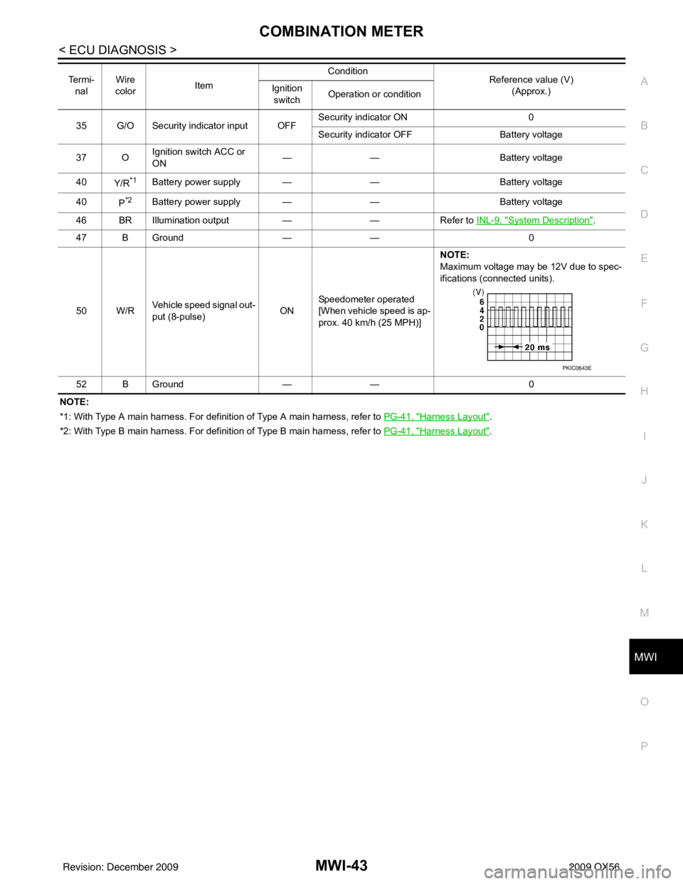
35 G/O Security indicator input OFF
Security indicator ON
0
Security indicator OFF Battery voltage
37 O Ignition switch ACC or
ON
—
— Battery voltage
40 Y/R
*1Battery power supply — —Battery voltage
40 P
*2Battery power supply — —Battery voltage
46 BR Illumination output ——Refer to INL-9, "
System Description".
47 B Ground —— 0
50 W/R Vehicle speed signal out-
put (8-pulse) ONSpeedometer operated
[When vehicle speed is ap-
prox. 40 km/h (25 MPH)] NOTE:
Maximum voltage may be 12V due to spec-
ifications (connected units).
52 B Ground —— 0
Te r m i -
nal Wire
color Item Condition
Reference value (V)
(Approx.)
Ignition
switch Operation or condition
PKIC0643E
Revision: December 20092009 QX56
Page 2766 of 4171
MWI-44
< ECU DIAGNOSIS >
COMBINATION METER
Wiring Diagram
INFOID:0000000003776654
AANWA0270GB
Revision: December 20092009 QX56
Page 2767 of 4171
MWI
COMBINATION METERMWI-45
< ECU DIAGNOSIS >
C
DE
F
G H
I
J
K L
M B A
O P
AANWA0275GB
Revision: December 20092009 QX56
Page 2768 of 4171
MWI-46
< ECU DIAGNOSIS >
COMBINATION METER
ABNWA0027GB
Revision: December 20092009 QX56