2009 INFINITI QX56 oil
[x] Cancel search: oilPage 3617 of 4171
ST-26
< REMOVAL AND INSTALLATION >
POWER STEERING OIL PUMP
POWER STEERING OIL PUMP
Removal and InstallationINFOID:0000000004187597
REMOVAL
1. Drain power steering fluid from reservoir tank.
2. Remove engine room cover. Refer to EM-24, "Removal and Installation"
.
3. Remove air duct assembly. Refer to EM-25, "Removal and Installation"
.
4. Remove power steering reservoir tank.
5. Remove serpentine drive belt belt from auto tensioner and power steering pump. Refer to EM-13,
"Removal and Installation".
6. Disconnect pressure sensor electrical connector.
7. Remove high pressure and low pressure piping from power steering oil pump. Refer to ST-27
.
8. Remove bolts, then remove power steering pump.
INSTALLATION
Installation is in the reverse order of removal. Refer to ST-27 for tightening torque.
After installation, bleed air. Refer to ST-13, "Air Bleeding Hydraulic System"
.
NOTE:
Belt tension is automatic and requires no adjustment.
Revision: December 20092009 QX56
Page 3618 of 4171
HYDRAULIC LINEST-27
< REMOVAL AND INSTALLATION >
C
DE
F
H I
J
K L
M A
B
ST
N
O P
HYDRAULIC LINE
Removal and InstallationINFOID:0000000004187598
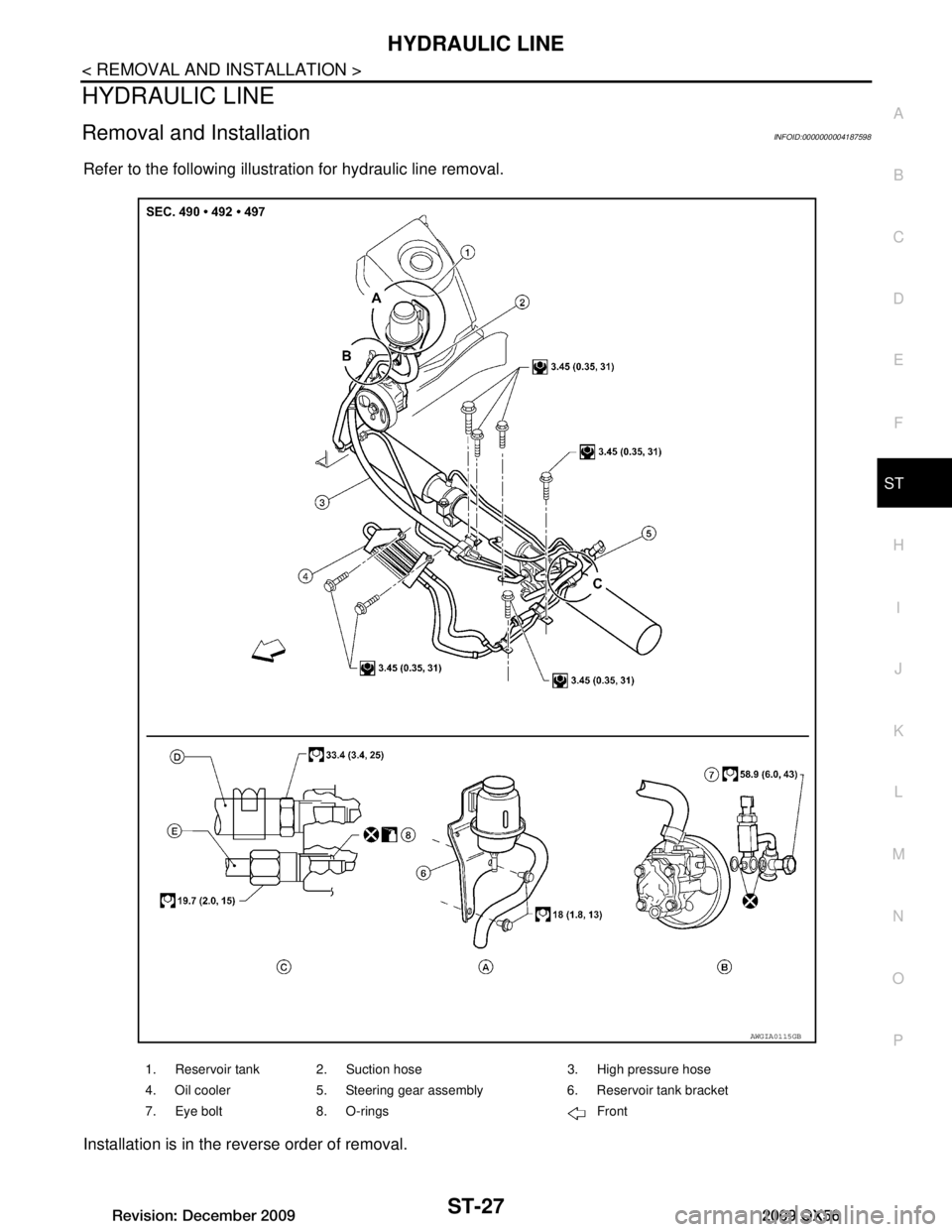
Refer to the following illustration for hydraulic line removal.
Installation is in the reverse order of removal.
1. Reservoir tank 2. Suction hose 3. High pressure hose
4. Oil cooler 5. Steering gear assembly 6. Reservoir tank bracket
7. Eye bolt 8. O-rings Front
AWGIA0115GB
Revision: December 20092009 QX56
Page 3623 of 4171
ST-32
< DISASSEMBLY AND ASSEMBLY >
POWER STEERING GEAR AND LINKAGE
POWER STEERING GEAR AND LINKAGE
Disassembly and AssemblyINFOID:0000000004187600
CAUTION:
Secure steering gear assembly with a vise, using copper plates or something similar to prevent it
from being damaged. Do not grip cylinder with a vise.
Before performing disassembly, clean steering gear assembly with kerosene. Be careful not to bring
any kerosene into contact with the discharge and return port connectors.
DISASSEMBLY
1. Remove cylinder tubes from gear housing assembly.
2. Loosen lock nuts of outer sockets, and remove outer sockets.
3. Remove boot clamps of the small diameter si de and the large diameter side, then remove boot.
CAUTION:
When removing boots, be careful not to damage inner socket and gear housing assembly. If they
are damaged, change them to avoid oil leaks.
4. Remove inner sockets.
INSPECTION AFTER DISASSEMBLY
Boot
Check boot for tears, cracks and def ormation. Replace if necessary.
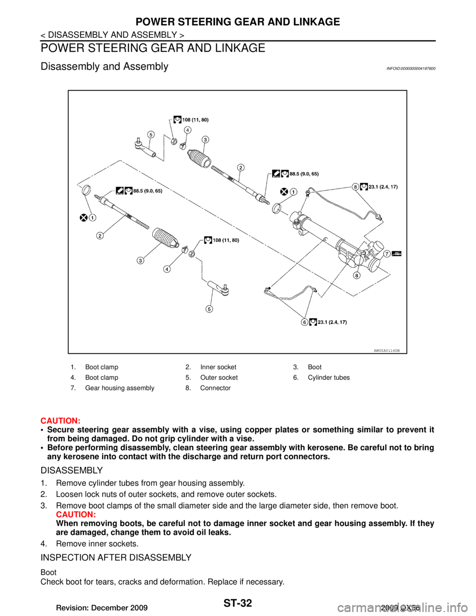
1. Boot clamp 2. Inner socket 3. Boot
4. Boot clamp 5. Outer socket 6. Cylinder tubes
7. Gear housing assembly 8. Connector
AWGIA0116GB
Revision: December 20092009 QX56
Page 3626 of 4171
POWER STEERING OIL PUMPST-35
< DISASSEMBLY AND ASSEMBLY >
C
DE
F
H I
J
K L
M A
B
ST
N
O P
POWER STEERING OIL PUMP
Disassembly and AssemblyINFOID:0000000004187601
INSPECTION BEFORE DISASSEMBLY
Disassemble the power steering oil pump only if the following items are found.
Deformed or damaged pulley, bracket, connector or suction pipe.
Oil leakage from the suction pipe or connector.
DISASSEMBLY
NOTE:
Mount the power steering oil pump in a vise as needed.
1. Remove the connector bolt, connector and copper washers. CAUTION:
Do not reuse the copper washers.
2. Remove the suction pipe and O-ring. CAUTION:
Do not reuse the O-ring.
3. Remove the pulley nut and pulley.
4. Remove the bracket bolts and bracket.
INSPECTION AFTER DISASSEMBLY
Body Assembly Inspection
Check the power steering oil pump body assembly fo r damage. If any damage is found, replace with a new
power steering oil pump assembly.
ASSEMBLY
Assembly is in the reverse order of disassembly.
CAUTION:
Do not reuse the copper gaskets
Do not reuse the O-ring. Apply a coat of Genuine Nissan PSF or equivalent to the O-ring.
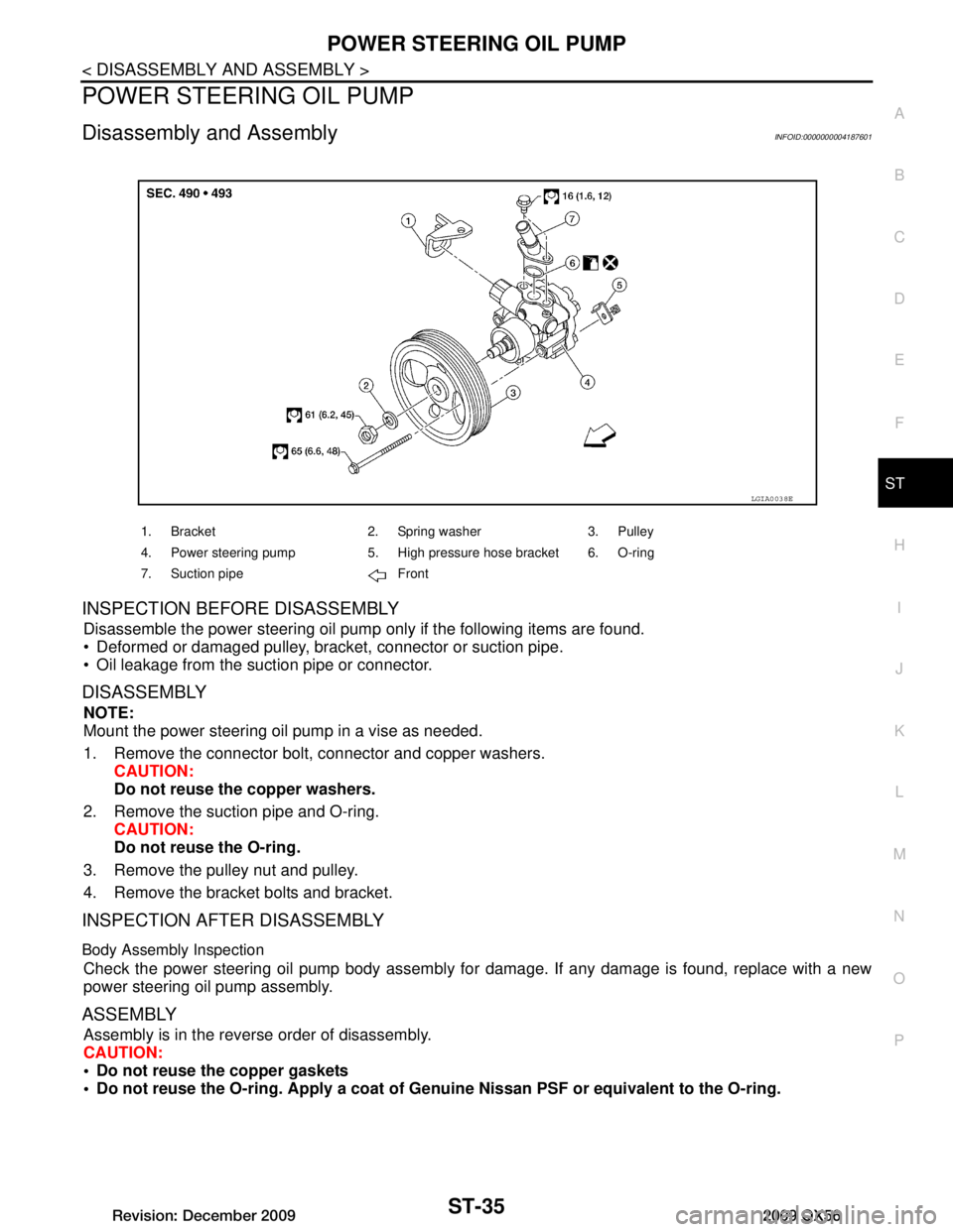
1. Bracket 2. Spring washer 3. Pulley
4. Power steering pump 5. High pressure hose bracket 6. O-ring
7. Suction pipe Front
LGIA0038E
Revision: December 20092009 QX56
Page 3629 of 4171

ST-38
< SERVICE DATA AND SPECIFICATIONS (SDS)
SERVICE DATA AND SPECIFICATIONS (SDS)
Steering Gear
INFOID:0000000004187589
Oil PumpINFOID:0000000004187590
Steering FluidINFOID:0000000004187591
Steering gear model PR26AM
Rack sliding force At the neutral point:
Range within
± 11.5 mm
( ± 0.453 in) from the neutral
position
(in power ON) Area average value 147
− 211 N (14.99 − 21.52 kg-f, 33.1 − 47.52 lb-f)
Allowable variation 98 N (10 kg-f, 22 lb-f) or less
Whole area (in power OFF) Peak value 294 N (30.0
kg-f, 66 lb-f) or less
Allowable variation 147 N (1 6 kg-f, 35 lb-f) or less
Relief oil pressure
9.0 − 9.8 mPa (91.77 − 99.93 kg/cm2 , 1305.34 − 1421.37 psi)
Fluid capacity
Approx. 1.0 (1-1/8 US qt, 7/8 Imp qt)
Revision: December 20092009 QX56
Page 3652 of 4171

TM-4
Precaution for Supplemental Restraint System
(SRS) "AIR BAG" and "SEAT BELT PRE-TEN-
SIONER" ................................................................
174
Precaution Necessary for Steering Wheel Rota-
tion After Battery Disconnect .................................
174
Precaution for On Board Diagnosis (OBD) System
of A/T and Engine ..................................................
175
Precaution .............................................................175
Service Notice or Precaution .................................176
PREPARATION ..........................................177
PREPARATION .............................................. .177
Special Service Tool ............................................ ..177
Commercial Service Tool ......................................178
ON-VEHICLE MAINTENANCE ..................179
A/T FLUID ....................................................... .179
Checking the A/T Fluid (ATF) .............................. ..179
Changing the A/T Fluid (ATF) ................................181
A/T FLUID COOLER ........................................183
A/T Fluid Cooler Cleaning ................................... ..183
Inspection ..............................................................185
STALL TEST ....................................................186
Inspection and Judgment .................................... ..186
LINE PRESSURE TEST ..................................188
Inspection and Judgment .................................... ..188
ROAD TEST .....................................................190
Description ........................................................... ..190
Check Before Engine Is Started ............................190
Check At Idle .........................................................190
Cruise Test - Part 1 ...............................................191
Cruise Test - Part 2 ...............................................193
Cruise Test - Part 3 ...............................................194
Vehicle Speed When Shifting Gears .....................194
Vehicle Speed When Performing and Releasing
Complete Lock-up .................................................
194
A/T POSITION .................................................195
Adjustment of A/T Position .................................. ..195
Checking of A/T Position .......................................195
ON-VEHICLE REPAIR ............................. ..196
SHIFT CONTROL SYSTEM ........................... .196
A/T Shift Selector Removal and Installation ........ ..196
AIR BREATHER HOSE ...................................197
2WD ........................................................................ ..197
2WD : Removal and Installation ............................197
4WD ........................................................................ ..197
4WD : Removal and Installation ............................197
OIL PAN ...........................................................201
Oil Pan ................................................................. .201
CONTROL VALVE WITH TCM ........................203
Control Valve with TCM and A/T Fluid Tempera-
ture Sensor 2 ....................................................... .
203
REAR OIL SEAL ..............................................212
Rear Oil Seal ........................................................ .212
FLUID COOLER SYSTEM ...............................213
Exploded View ..................................................... .213
Removal and Installation .......................................213
REMOVAL AND INSTALLATION .............214
TRANSMISSION ASSEMBLY ........................ ..214
Removal and Installation (2WD) .......................... .214
Removal and Installation (4WD) ...........................216
DISASSEMBLY AND ASSEMBLY ...........220
OVERHAUL .................................................... ..220
Component .......................................................... .220
Oil Channel ...........................................................227
Location of Adjusting Shims, Needle Bearings,
Thrust Washers and Snap Rings ......................... .
229
DISASSEMBLY .............................................. ..232
Disassembly ......................................................... .232
REPAIR FOR COMPONENT PARTS ..............249
Oil Pump .............................................................. .249
Front Sun Gear, 3rd One-Way Clutch ...................251
Front Carrier, Input Clutch, Rear Internal Gear .....253
Mid Sun Gear, Rear Sun Gear, High and Low Re-
verse Clutch Hub ..................................................
258
High and Low Reverse Clutch ..............................263
Direct Clutch .........................................................265
ASSEMBLY .................................................... ..268
Assembly (1) ........................................................ .268
Adjustment ............................................................281
Assembly (2) .........................................................283
SERVICE DATA AND SPECIFICATIONS
(SDS) ............... ..........................................
290
SERVICE DATA AND SPECIFICATIONS
(SDS) .............................................................. ..
290
General Specification ........................................... .290
Vehicle Speed at Which Gear Shifting Occurs .....290
Vehicle Speed at Which Lock-up Occurs/Releas-
es ..........................................................................
291
Stall Speed ............................................................291
Line Pressure ........................................................291
Input Speed Sensor ..............................................291
Output Speed Sensor ...........................................291
Reverse Brake ......................................................291
Total End Play .......................................................292
Torque Converter .................................................
Revision: December 20092009 QX56
Page 3656 of 4171
TM-8
< FUNCTION DIAGNOSIS >
A/T CONTROL SYSTEM
FUNCTION DIAGNOSIS
A/T CONTROL SYSTEM
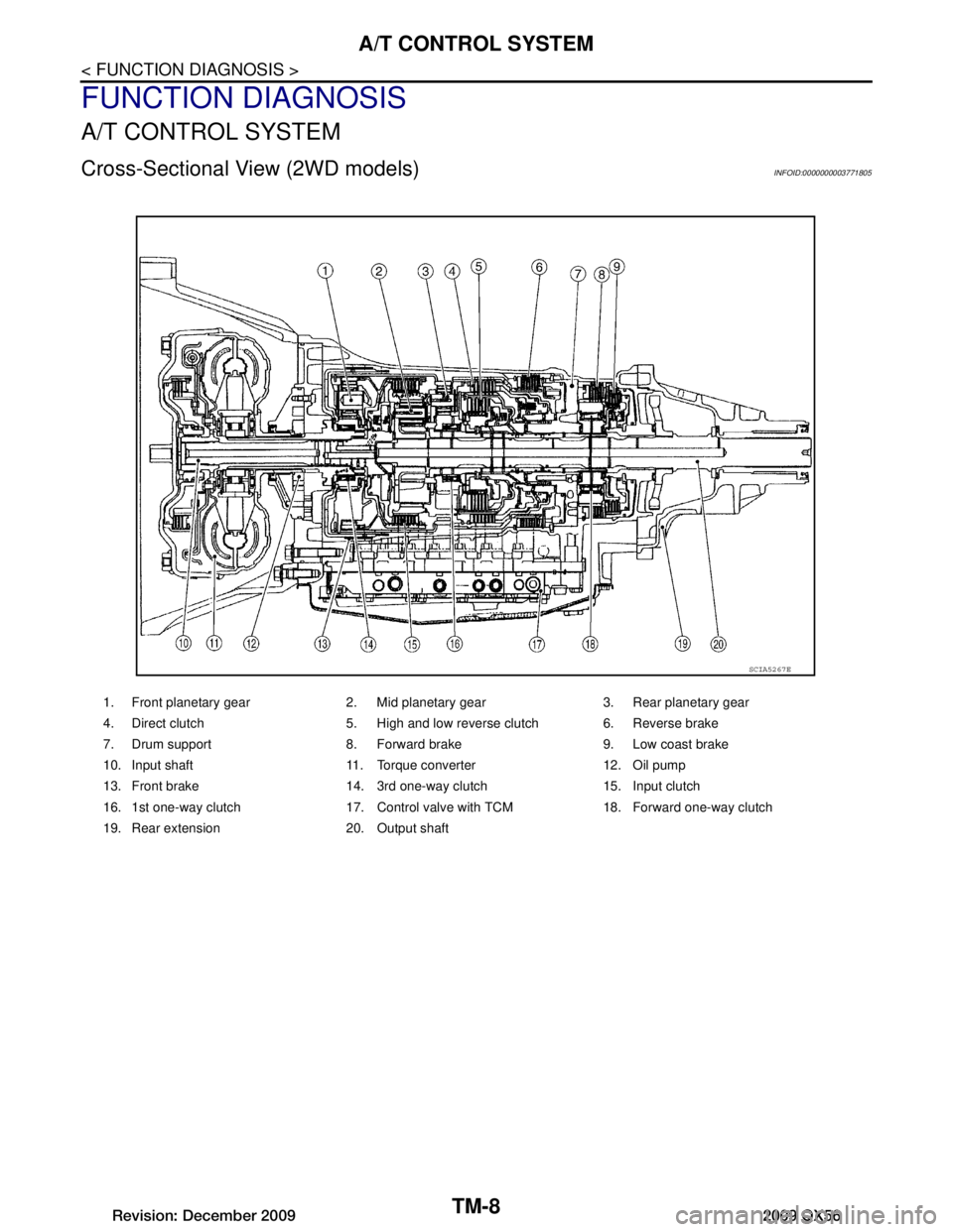
Cross-Sectional View (2WD models)INFOID:0000000003771805
1. Front planetary gear 2. Mid planetary gear 3. Rear planetary gear
4. Direct clutch 5. High and low reverse clutch 6. Reverse brake
7. Drum support 8. Forward brake 9. Low coast brake
10. Input shaft 11. Torque converter 12. Oil pump
13. Front brake 14. 3rd one-way clutch 15. Input clutch
16. 1st one-way clutch 17. Control valve with TCM 18. Forward one-way clutch
19. Rear extension 20. Output shaft
SCIA5267E
Revision: December 20092009 QX56
Page 3657 of 4171
A/T CONTROL SYSTEMTM-9
< FUNCTION DIAGNOSIS >
CEF
G H
I
J
K L
M A
B
TM
N
O P
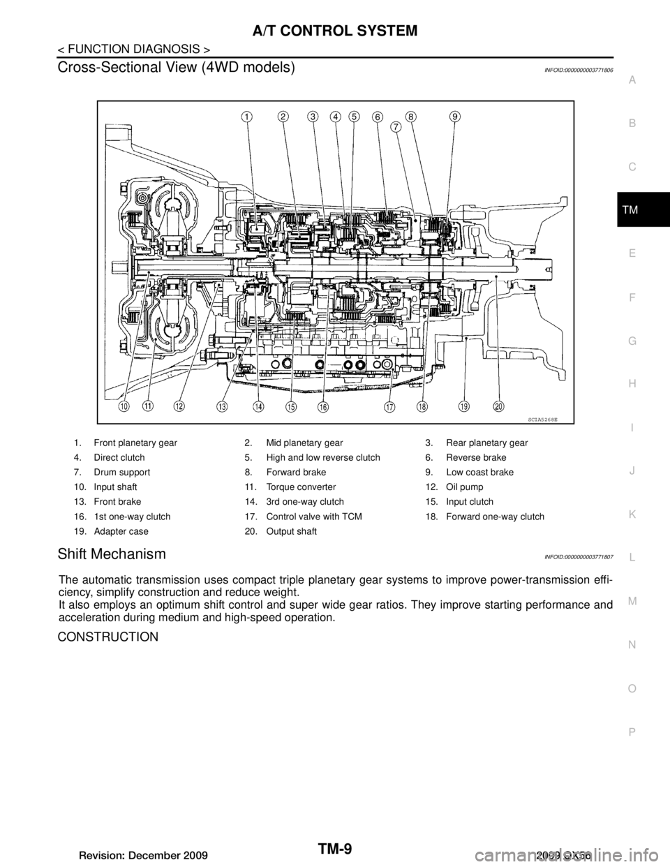
Cross-Sectional View (4WD models)INFOID:0000000003771806
Shift MechanismINFOID:0000000003771807
The automatic transmission uses compact triple planet ary gear systems to improve power-transmission effi-
ciency, simplify construction and reduce weight.
It also employs an optimum shift control and super wide gear ratios. They improve starting performance and
acceleration during medium and high-speed operation.
CONSTRUCTION
1. Front planetary gear 2. Mid planetary gear 3. Rear planetary gear
4. Direct clutch 5. High and low reverse clutch 6. Reverse brake
7. Drum support 8. Forward brake 9. Low coast brake
10. Input shaft 11. Torque converter 12. Oil pump
13. Front brake 14. 3rd one-way clutch 15. Input clutch
16. 1st one-way clutch 17. Control valve with TCM 18. Forward one-way clutch
19. Adapter case 20. Output shaft
SCIA5268E
Revision: December 20092009 QX56