2009 INFINITI QX56 oil
[x] Cancel search: oilPage 3164 of 4171
RSU-16
< REMOVAL AND INSTALLATION >
SHOCK ABSORBER
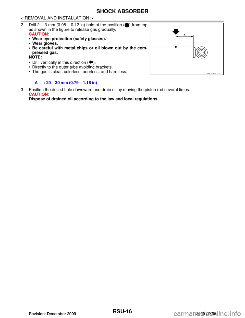
2. Drill 2 – 3 mm (0.08 – 0.12 in) hole at the position ( ) from topas shown in the figure to release gas gradually.
CAUTION:
Wear eye protection (safety glasses).
Wear gloves.
Be careful with metal chips or oil blown out by the com-pressed gas.
NOTE:
Drill vertically in this direction ( ).
Directly to the outer tube avoiding brackets.
The gas is clear, colorless, odorless, and harmless.
3. Position the drilled hole downward and drain oil by moving the piston rod several times. CAUTION:
Dispose of drained oil according to the law and local regulations.
A : 20 – 30 mm (0.79 – 1.18 in)
JPEIA0161ZZ
Revision: December 20092009 QX56
Page 3165 of 4171
SUSPENSION ARMRSU-17
< REMOVAL AND INSTALLATION >
C
DF
G H
I
J
K L
M A
B
RSU
N
O P
SUSPENSION ARM
Removal and InstallationINFOID:0000000005889874
REMOVAL
1. If equipped with rear load leveling air suspension system, use CONSULT-III “EXHAUST SOLENOID”
active test to release the air pressure from the rear load leveling air suspension system.
2. If equipped with the rear load leveling air suspension system, disconnect the electrical connectors for the
height sensor and the rear load leveling air suspension compressor assembly.
3. If equipped with the rear load leveling air suspension system, unclip the rubber cover to access the rear
load leveling air suspension compressor assembly.
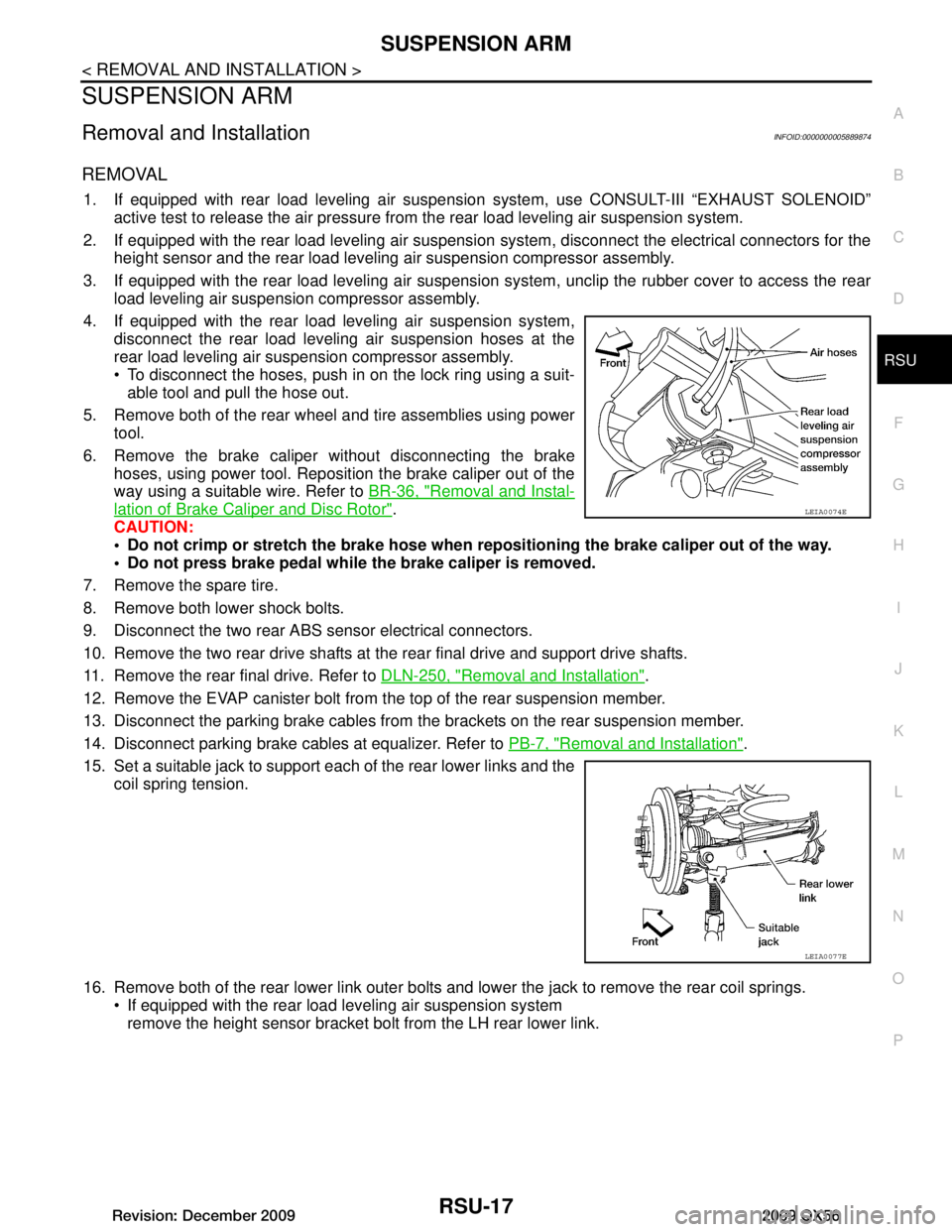
4. If equipped with the rear load leveling air suspension system, disconnect the rear load leveling air suspension hoses at the
rear load leveling air suspension compressor assembly.
To disconnect the hoses, push in on the lock ring using a suit-able tool and pull the hose out.
5. Remove both of the rear wheel and tire assemblies using power tool.
6. Remove the brake caliper without disconnecting the brake hoses, using power tool. Reposition the brake caliper out of the
way using a suitable wire. Refer to BR-36, "Removal and Instal-
lation of Brake Caliper and Disc Rotor".
CAUTION:
Do not crimp or stretch the brake hose when re positioning the brake caliper out of the way.
Do not press brake pedal while the brake caliper is removed.
7. Remove the spare tire.
8. Remove both lower shock bolts.
9. Disconnect the two rear ABS sensor electrical connectors.
10. Remove the two rear drive shafts at t he rear final drive and support drive shafts.
11. Remove the rear final drive. Refer to DLN-250, "Removal and Installation"
.
12. Remove the EVAP canister bolt from the top of the rear suspension member.
13. Disconnect the parking brake cables from t he brackets on the rear suspension member.
14. Disconnect parking brake cables at equalizer. Refer to PB-7, "Removal and Installation"
.
15. Set a suitable jack to support each of the rear lower links and the coil spring tension.
16. Remove both of the rear lower link outer bolts and lower the jack to remove the rear coil springs. If equipped with the rear load leveling air suspension systemremove the height sensor bracket bolt from the LH rear lower link.
LEIA0074E
LEIA0077E
Revision: December 20092009 QX56
Page 3169 of 4171
REAR LOWER LINK & COIL SPRINGRSU-21
< REMOVAL AND INSTALLATION >
C
DF
G H
I
J
K L
M A
B
RSU
N
O P
REAR LOWER LINK & COIL SPRING
Removal and InstallationINFOID:0000000005889876
REMOVAL
1. Remove the wheel and tire assembly using power tool. Refer to WT-41, "Adjustment".
2. If equipped with rear load leveling air suspension system, use CONSULT-III “EXHAUST SOLENOID”
active test to release the air pressure from the rear load leveling air suspension system.
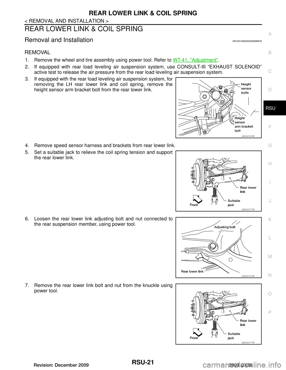
3. If equipped with the rear load leveling air suspension system, for removing the LH rear lower link and coil spring, remove the
height sensor arm bracket bolt from the rear lower link.
4. Remove speed sensor harness and brackets from rear lower link.
5. Set a suitable jack to relieve the coil spring tension and support the rear lower link.
6. Loosen the rear lower link adjusting bolt and nut connected to the rear suspension member, using power tool.
7. Remove the rear lower link bolt and nut from the knuckle using power tool.
LEIA0080E
LEIA0077E
LEIA0009E
LEIA0077E
Revision: December 20092009 QX56
Page 3170 of 4171
RSU-22
< REMOVAL AND INSTALLATION >
REAR LOWER LINK & COIL SPRING
8. Slowly lower the suitable jack to release the coil spring tension. Then remove the upper rubber seat, coil
spring and lower rubber seat from the rear lower link.
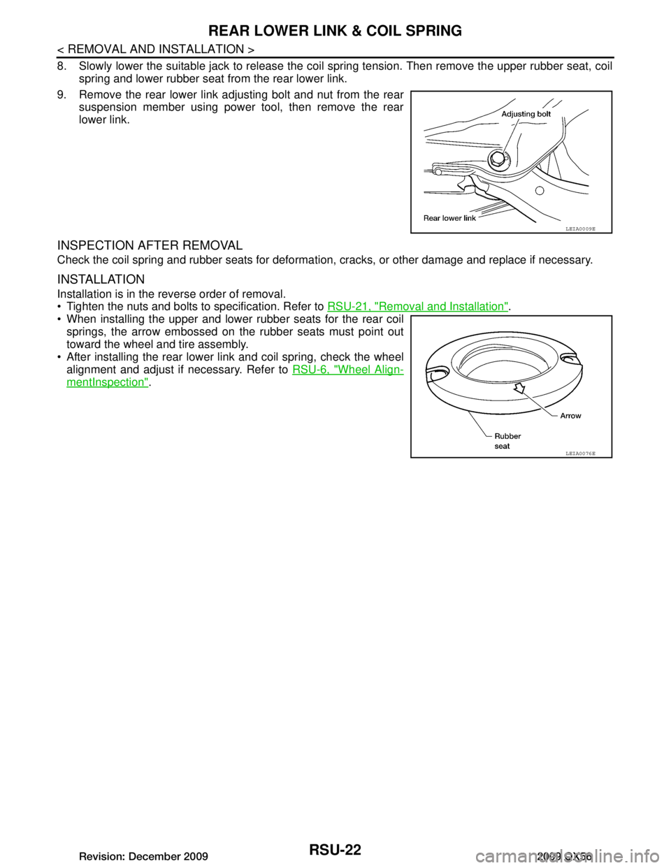
9. Remove the rear lower link adjusting bolt and nut from the rear suspension member using power tool, then remove the rear
lower link.
INSPECTION AFTER REMOVAL
Check the coil spring and rubber seats for deformation, cracks, or other damage and replace if necessary.
INSTALLATION
Installation is in the reverse order of removal.
Tighten the nuts and bolts to specification. Refer to RSU-21, "Removal and Installation"
.
When installing the upper and lower rubber seats for the rear coil springs, the arrow embossed on the rubber seats must point out
toward the wheel and tire assembly.
After installing the rear lower link and coil spring, check the wheel alignment and adjust if necessary. Refer to RSU-6, "Wheel Align-
mentInspection".
LEIA0009E
LEIA0076E
Revision: December 20092009 QX56
Page 3177 of 4171
SERVICE DATA AND SPECIFICATIONS (SDS)
RSU-29
< SERVICE DATA AND SPECIFICATIONS (SDS)
C
D F
G H
I
J
K L
M A
B
RSU
N
O P
SERVICE DATA AND SPECIFICATIONS (SDS)
SERVICE DATA AND SPECIFICATIONS (SDS)
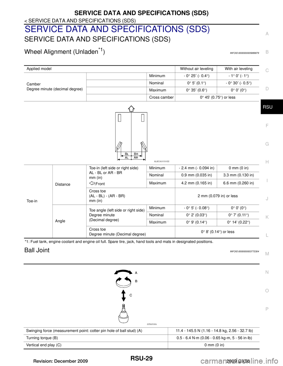
Wheel Alignment (Unladen*1)INFOID:0000000005889879
*1: Fuel tank, engine coolant and engine oil full. Spare tire, jack, hand tools and mats in designated positions.
Ball JointINFOID:0000000003772304
Applied model Without air leveling With air leveling
Camber
Degree minute (decimal degree) Minimum - 0
° 25 ′ (- 0.4 °)- 1 ° 0 ′ (- 1 °)
Nominal 0 ° 5 ′ (0.1 °)- 0 ° 30 ′ (- 0.5 °)
Maximum 0 ° 35 ′ (0.6 °)0 ° 0 ′ (0 °)
Cross camber 0 ° 45' (0.75 °) or less
To e - i n Distance
Toe-in (left side or right side)
AL - BL or AR - BR
mm (in)
:Front Minimum - 2.4 mm (- 0.094 in) 0 mm (0 in)
Nominal 0.9 mm (0.035 in) 3.3 mm (0.130 in)
Maximum 4.2 mm (0.165 in) 6.6 mm (0.260 in)
Cross toe
(AL - BL) - (AR - BR)
mm (in) 2 mm (0.079 in) or less
Angle Toe angle (left side or right side)
Degree minute
(Decimal degree) Minimum - 0
° 5' (- 0.08 °)0 ° 0' (0 °)
Nominal 0 ° 2' (0.03 °)0 ° 7' (0.11 °)
Maximum 0 ° 9' (0.14 °)0 ° 14' (0.22 °)
Cross toe
Degree minute (Decimal degree) 0
° 8' (0.14 °) or less
ALEIA0059ZZ
Swinging force (measurement point: cotter pin hole of ball stud) (A) 11.4 - 145.5 N (1.16 - 14.8 kg, 2.56 - 32.7 lb)
Turning torque (B) 0.5 - 6.4 N·m (0.06 - 0.65 kg-m, 5 - 56 in-lb)
Vertical end play (C) 0 mm (0 in)
SFA858A
Revision: December 20092009 QX56
Page 3178 of 4171
RSU-30
< SERVICE DATA AND SPECIFICATIONS (SDS)
SERVICE DATA AND SPECIFICATIONS (SDS)
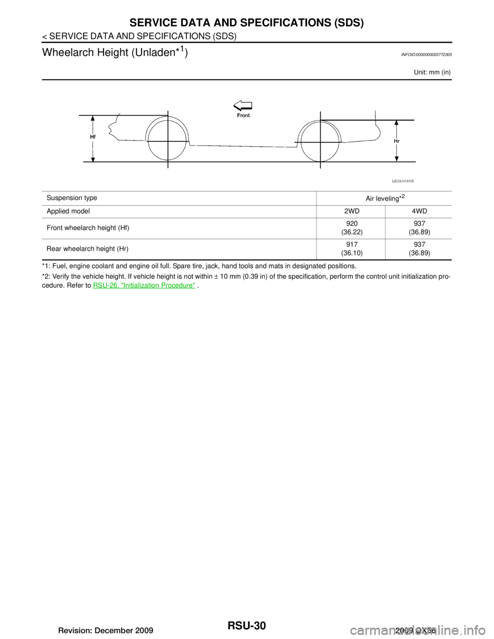
Wheelarch Height (Unladen*
1)INFOID:0000000003772305
Unit: mm (in)
*1: Fuel, engine coolant and engine oil full. Spare tire, jack, hand tools and mats in designated positions.
*2: Verify the vehicle height. If vehicle height is not within ± 10 mm (0.39 in) of the specification, perform the control unit initialization pro-
cedure. Refer to RSU-26, "Initialization Procedure"
.
Suspension type
Air leveling*
2
Applied model2WD 4WD
Front wheelarch height (Hf) 920
(36.22) 937
(36.89)
Rear wheelarch height (Hr) 917
(36.10) 937
(36.89)
LEIA0085E
Revision: December 20092009 QX56
Page 3181 of 4171
PRECAUTIONSSB-3
< PRECAUTION >
C
DE
F
G
I
J
K L
M A
B
SB
N
O P
5. When the repair work is completed, return the ignition switch to the ″LOCK ″ position before connecting
the battery cables. (At this time, the steering lock mechanism will engage.)
6. Perform a self-diagnosis check of al l control units using CONSULT-III.
Precaution for Seat Belt ServiceINFOID:0000000003775146
CAUTION:
• Before removing the seat belt pre-tensioner assembly, turn the ignition switch OFF, disconnect both
battery cables and wait at least 3 minutes.
• After replacing or reinstalling seat belt pre-tensioner assembly, or reconnecting seat belt pre-ten- sioner assembly connector, make sure entire SRS operates properly. Refer to SRC-13, "
SRS Opera-
tion Check".
• Do not disassemble buckle or seat belt assembly.
• Do not reuse seat belt anchor bolts after removal. Replace with new ones.
• Replace anchor bolts if th ey are deformed or worn out.
• Never oil tongue and buckle.
• If any component of seat belt assembly is questio nable, do not repair. Replace the whole seat belt
assembly.
• If webbing is cut, frayed, or damaged, replace seat belt assembly.
• When replacing seat belt assembly, u se a genuine NISSAN seat belt assembly.
AFTER A COLLISION
WARNING:
• Inspect all seat belt assemblies including retractors and attaching hardware after any collision.
• NISSAN recommends that all seat belt assemblies in use during a collision be replaced unless the
collision was minor and the belts show no damage and continue to operate properly. Failure to do so
could result in serious personal injury in an acci dent. Seat belt assemblies not in use during a colli-
sion should also be replaced if either damage or im proper operation is noted. Seat belt pre-tensioner
should be replaced even if the seat belts are not in use during a frontal collision in which the air bags
are deployed.
Replace any seat belt assembly (including anchor bolts) if:
• The seat belt was in use at the time of a collision (except for minor collisions and the belts, retractors and
buckles show no damage and continue to operate properly).
• The seat belt was damaged in an accident. (i.e., torn webbing, bent retractor or guide, etc.)
• The seat belt attaching point was damaged in an accident. Inspect the seat belt attaching area for damage or distortion and repair as necessary before installing a new seat belt assembly.
• Anchor bolts are deformed or worn out.
• The seat belt pre-tensioner should be replaced even if t he seat belts are not in use during the collision in
which the air bags are deployed.
Revision: December 20092009 QX56
Page 3203 of 4171
SCS-10
< COMPONENT DIAGNOSIS >
C1802 COMPRESSOR RELAY
C1802 COMPRESSOR RELAY
DescriptionINFOID:0000000003772315
The compressor motor relay is controlled by the suspension control unit. The suspension control unit supplies
voltage to the coil side of the relay to activate it. T he compressor motor relay, when activated, supplies power
to the suspension air compressor.
DTC LogicINFOID:0000000003772316
DTC DETECTION LOGIC
Diagnosis ProcedureINFOID:0000000003772317
1.CHECK COMPRESSOR MOTOR RELAY OPERATION
CAUTION:
The "COMPRESSOR" active test will remain ON until it is turned off using CONSULT-III. Allowing the
compressor to run for an extended period of time may cause damage to the air levelizer system com-
ponents due to excessive air pressure.
CONSULT-III
1. Turn ignition ON.
2. Select "COMPRESSOR" of AIR LEVELIZER active test items.
3. While operating test item, check that the suspension air compressor turns ON.
Does the suspension air compressor operate properly?
YES >> Compressor motor relay and suspension air compressor are operating normally.
NO >> Refer to SCS-20, "
Diagnosis Procedure".
DTCDisplay contents of CON-
SULT-III Diagnostic item is detected when ...
Probable malfunction location
C1802 COMPRESSOR RELAY • Driving transistor for the compressor
relay is
OFF and monitor voltage continues at a high
level for more than 10 seconds.
• Driving transistor for the compressor relay is
ON and monitor voltage continues at a low
level for more than 5 seconds. Compressor motor relay. Refer to
SCS-20,
"Component Function Check".
ON : Compressor turns ON
OFF : Compressor turns OFF
Revision: December 20092009 QX56