2009 INFINITI QX56 brake rotor
[x] Cancel search: brake rotorPage 2830 of 4171
PARKING BRAKE SYSTEMPB-5
< ON-VEHICLE MAINTENANCE >
C
DE
G H
I
J
K L
M A
B
PB
N
O P
ON-VEHICLE MAINTENANCE
PARKING BRAKE SYSTEM
On-Vehicle ServiceINFOID:0000000003772470
PEDAL STROKE
• When parking brake pedal is operated with the specified forc e, make sure the stroke is within the specified
number of notches. Check by listening and counting the ratchet clicks.
INSPECTION
• Make sure the components are attached pr operly, checking for looseness or backlash.
• Check parking brake pedal assembly for bends, damage and cracks, and replace if necessary.
• Check cable for wear and damage, and replace if necessary.
• Check parking brake warning lamp switch for malfunction, and replace if necessary. Refer to BCS-36, "
Diag-
nosis Procedure".
ADJUSTMENT
1. Remove the lower instrument panel LH. Refer to IP-15, "Exploded View".
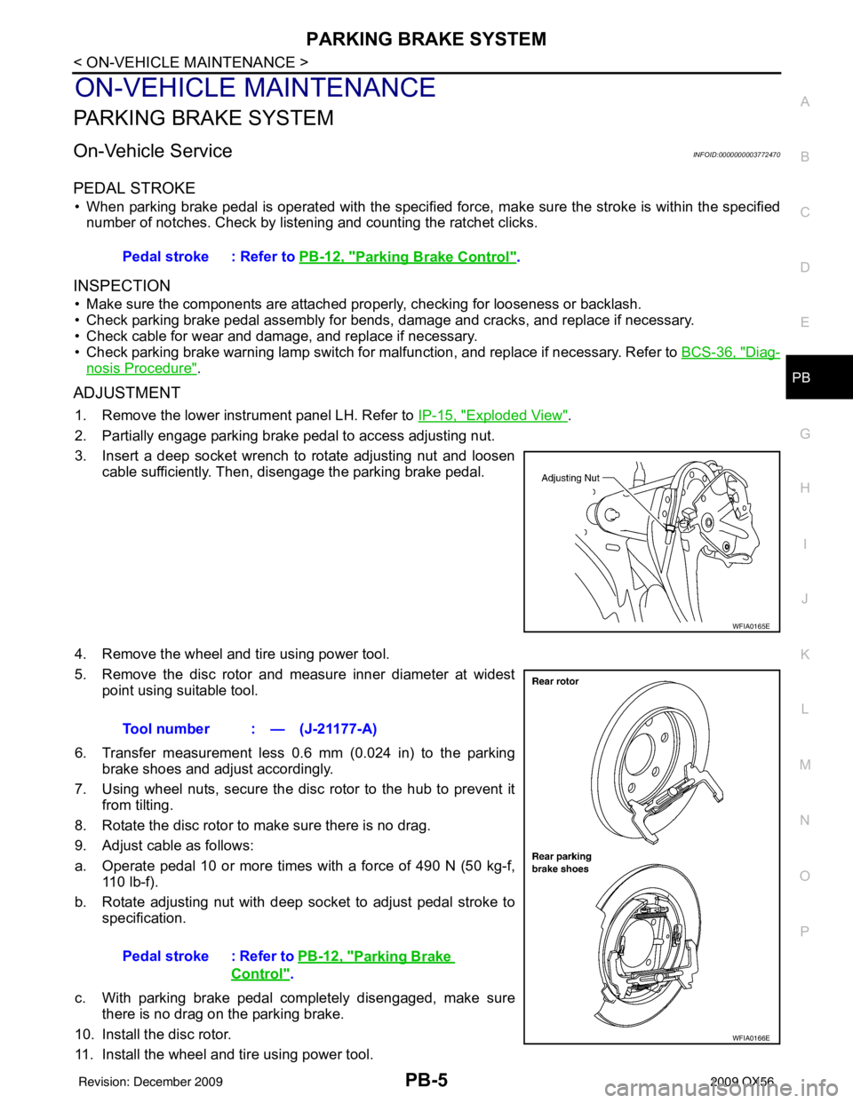
2. Partially engage parking brake pedal to access adjusting nut.
3. Insert a deep socket wrench to rotate adjusting nut and loosen cable sufficiently. Then, disengage the parking brake pedal.
4. Remove the wheel and tire using power tool.
5. Remove the disc rotor and measure inner diameter at widest point using suitable tool.
6. Transfer measurement less 0.6 mm (0.024 in) to the parking brake shoes and adjust accordingly.
7. Using wheel nuts, secure the disc rotor to the hub to prevent it from tilting.
8. Rotate the disc rotor to make sure there is no drag.
9. Adjust cable as follows:
a. Operate pedal 10 or more times with a force of 490 N (50 kg-f, 110 lb-f).
b. Rotate adjusting nut with deep socket to adjust pedal stroke to specification.
c. With parking brake pedal completely disengaged, make sure there is no drag on the parking brake.
10. Install the disc rotor.
11. Install the wheel and tire using power tool. Pedal stroke : Refer to
PB-12, "
Parking Brake Control".
WFIA0165E
Tool number : — (J-21177-A)
Pedal stroke : Refer to PB-12, "
Parking Brake
Control".
WFIA0166E
Revision: December 20092009 QX56
Page 2834 of 4171
PARKING BRAKE SHOEPB-9
< ON-VEHICLE REPAIR >
C
DE
G H
I
J
K L
M A
B
PB
N
O P
PARKING BRAKE SHOE
Removal and InstallationINFOID:0000000003772473
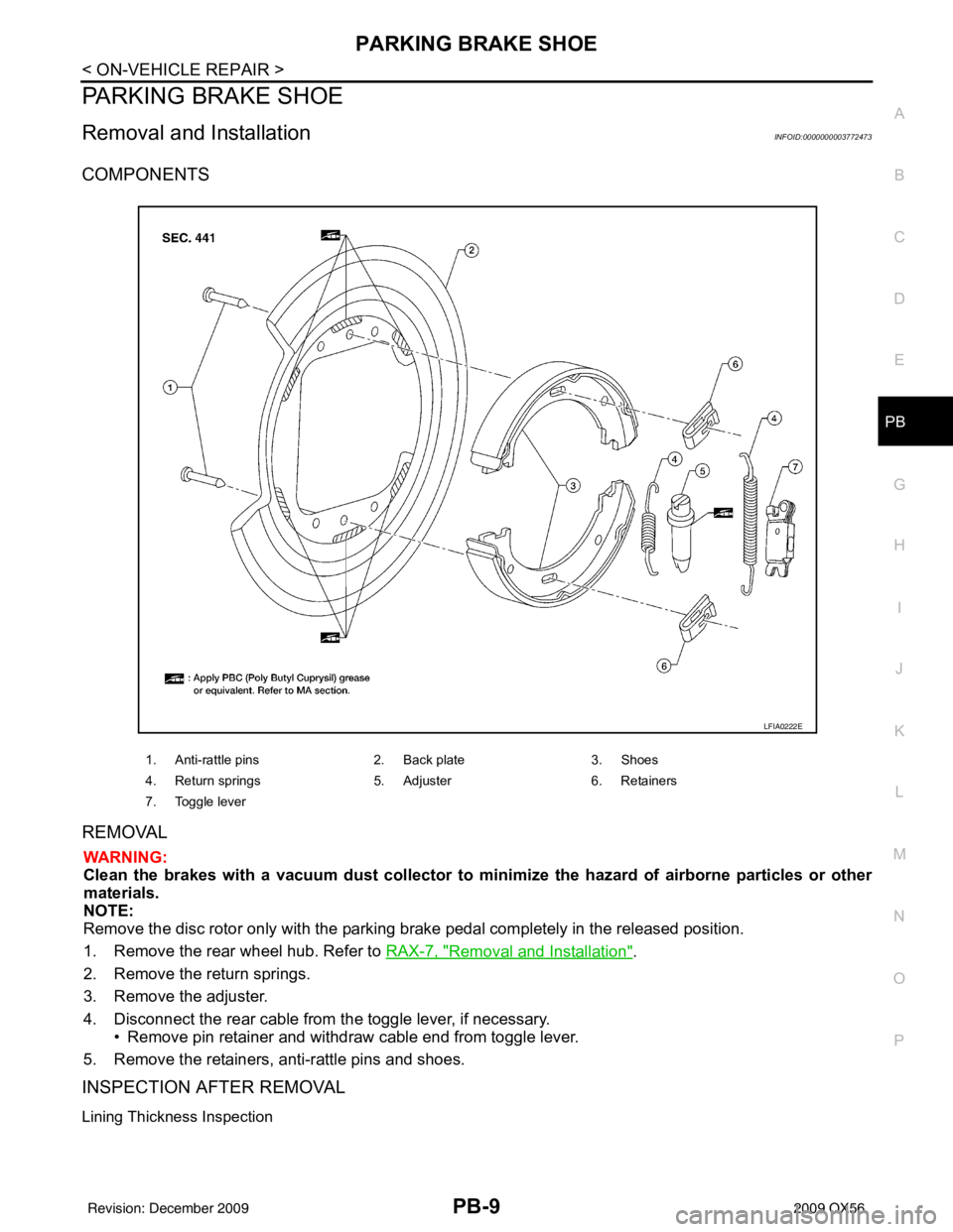
COMPONENTS
REMOVAL
WARNING:
Clean the brakes with a vacuum dust co llector to minimize the hazard of airborne particles or other
materials.
NOTE:
Remove the disc rotor only with the parking brake pedal completely in the released position.
1. Remove the rear wheel hub. Refer to RAX-7, "
Removal and Installation".
2. Remove the return springs.
3. Remove the adjuster.
4. Disconnect the rear cable from the toggle lever, if necessary.
• Remove pin retainer and withdraw cable end from toggle lever.
5. Remove the retainers, anti-rattle pins and shoes.
INSPECTION AFTER REMOVAL
Lining Thickness Inspection
1. Anti-rattle pins 2. Back plate3. Shoes
4. Return springs 5. Adjuster6. Retainers
7. Toggle lever
LFIA0222E
Revision: December 20092009 QX56
Page 2835 of 4171

PB-10
< ON-VEHICLE REPAIR >
PARKING BRAKE SHOE
• Check thickness of lining.
Disc Rotor Inner Diameter Inspection
• Check inner diameter insi de drum area of disc rotor.
Other Inspections
• Check shoe sliding surface on back plate for excessive wear and damage.
• Check anti-rattle pins for excessive wear and corrosion.
• Check return springs for sagging.
• Check adjuster for rough operation.
• When disassembling adjuster, apply PBC (Poly Butyl Cuprysil) grease or equivalent to the threads.
• Check either visually or with a vernier caliper to see if there is any excessive wear, cracks, or damage inside
drum area of disc rotor.
INSTALLATION
Installation is in the reverse order of removal.
• Apply brake grease to the specified points during assembly.
• Assemble adjuster so that threaded part expands when rotating it
in the direction shown by the arrow.
• Shorten adjuster by rotating it.
NOTE:
After replacing brake shoes or disc rotors, or if brakes do not function well, perform break-in operation as fol-
lows.
1. Adjust parking brake pedal stroke. Refer to PB-5, "
On-Vehicle Service".
2. Perform parking brake break-in operation by driving the vehicle forward under the following conditions: • Vehicle speed at 40 km/h (25 MPH)
• Apply parking brake with an operating forc e of 196 N (20.0 kg-f, 44.1 lb-f) set
• Apply parking brake for a period of 30 seconds
CAUTION:
• To prevent lining from getting too hot, allow a cool off period of approximately 5 minutes after every break-in operation.Standard thickness (A) : Refer to
PB-12, "
Parking
Brake".
Wear limit thickness (A) : Refer to PB-12, "
Parking
Brake".
SBR021A
Standard inner diameter : Refer to PB-12, "Park-
ing Brake".
Wear limit of inner diameter : Refer to PB-12, "
Park-
ing Brake".
SBR768A
SFIA0153E
Revision: December 20092009 QX56
Page 2837 of 4171

PB-12
< SERVICE DATA AND SPECIFICATIONS (SDS)
SERVICE DATA AND SPECIFICATIONS (SDS)
SERVICE DATA AND SPECIFICATIONS (SDS)
SERVICE DATA AND SPECIFICATIONS (SDS)
Parking BrakeINFOID:0000000003772474
Unit: mm (in)
Parking Brake ControlINFOID:0000000003772475
Typ eDisc rotor with inner drum
Brake lining Standard thickness (new)
3.79 ± 0.21 (0.149 ± 0.008)
Wear limit thickness 0.5 (0.020)
Drum inner diameter (disc) Standard inner diameter (new)
205 ± 0.13 (8.07 ± 0.01)
Wear limit of inner diameter 205.7 (8.10)
Control type Foot pedal
Number of notches [under force of 196 N (20.0 kg-f, 44.1 lb-f)] 3 – 4 notches
Number of notches when warning lamp switch comes on 1 notch
Revision: December 20092009 QX56
Page 3082 of 4171
WHEEL HUBRAX-7
< REMOVAL AND INSTALLATION >
CEF
G H
I
J
K L
M A
B
RAX
N
O P
REMOVAL AND INSTALLATION
WHEEL HUB
Removal and InstallationINFOID:0000000003772260
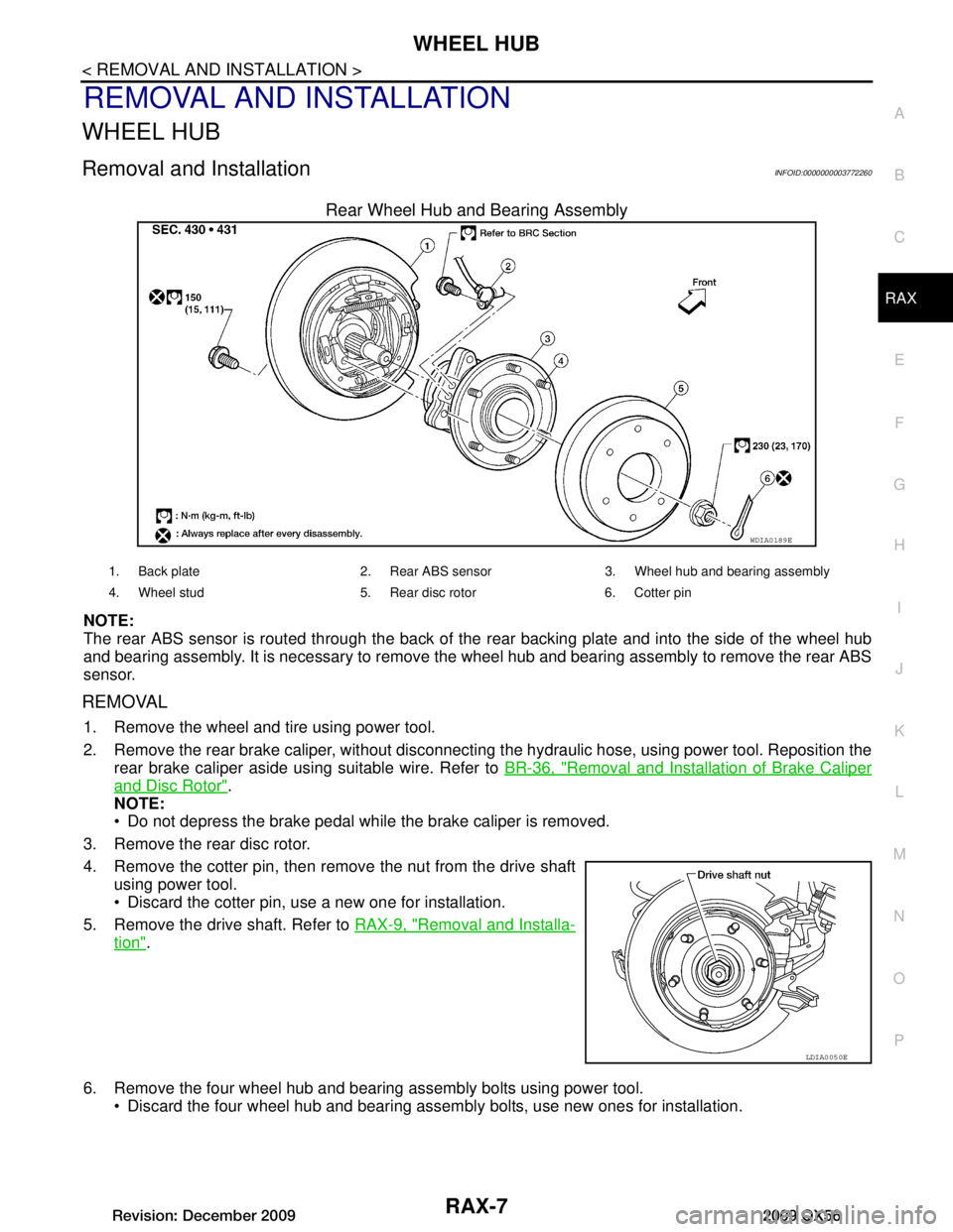
Rear Wheel Hub and Bearing Assembly
NOTE:
The rear ABS sensor is routed through the back of t he rear backing plate and into the side of the wheel hub
and bearing assembly. It is necessary to remove the wheel hub and bearing assembly to remove the rear ABS
sensor.
REMOVAL
1. Remove the wheel and tire using power tool.
2. Remove the rear brake caliper, without disconnecting t he hydraulic hose, using power tool. Reposition the
rear brake caliper aside using suitable wire. Refer to BR-36, "Removal and Installation of Brake Caliper
and Disc Rotor".
NOTE:
Do not depress the brake pedal while the brake caliper is removed.
3. Remove the rear disc rotor.
4. Remove the cotter pin, then remove the nut from the drive shaft using power tool.
Discard the cotter pin, use a new one for installation.
5. Remove the drive shaft. Refer to RAX-9, "Removal and Installa-
tion".
6. Remove the four wheel hub and bearing assembly bolts using power tool. Discard the four wheel hub and bearing assembly bolts, use new ones for installation.
WDIA0189E
1. Back plate 2. Rear ABS sensor 3. Wheel hub and bearing assembly
4. Wheel stud 5. Rear disc rotor 6. Cotter pin
LDIA0050E
Revision: December 20092009 QX56
Page 3161 of 4171
REAR SUSPENSION MEMBERRSU-13
< REMOVAL AND INSTALLATION >
C
DF
G H
I
J
K L
M A
B
RSU
N
O P
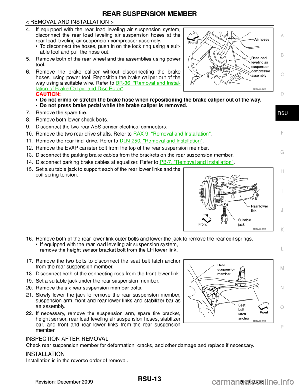
4. If equipped with the rear load leveling air suspension system, disconnect the rear load leveling air suspension hoses at the
rear load leveling air suspension compressor assembly.
To disconnect the hoses, push in on the lock ring using a suit-
able tool and pull the hose out.
5. Remove both of the rear wheel and tire assemblies using power tool.
6. Remove the brake caliper without disconnecting the brake hoses, using power tool. Reposition the brake caliper out of the
way using a suitable wire. Refer to BR-36, "Removal and Instal-
lation of Brake Caliper and Disc Rotor".
CAUTION:
Do not crimp or stretch the brake hose when re positioning the brake caliper out of the way.
Do not press brake pedal while the brake caliper is removed.
7. Remove the spare tire.
8. Remove both lower shock bolts.
9. Disconnect the two rear ABS sensor electrical connectors.
10. Remove the two rear drive shafts. Refer to RAX-9, "Removal and Installation"
.
11. Remove the rear final drive. Refer to DLN-250, "Removal and Installation"
.
12. Remove the EVAP canister bolt from the top of the rear suspension member.
13. Disconnect the parking brake cables from t he brackets on the rear suspension member.
14. Disconnect parking brake cables at equalizer. Refer to PB-7, "Removal and Installation"
.
15. Set a suitable jack to support each of the rear lower links and the coil spring tension.
16. Remove both of the rear lower link outer bolts and lower the jack to remove the rear coil springs. If equipped with the rear load leveling air suspension system,
remove the height sensor bracket bolt from the LH lower link.
17. Remove the two bolts to disconnect the seat belt latch anchor from the rear suspension member.
18. Disconnect both of the connecting r ods from the front lower link.
19. Set a suitable jack under the rear suspension member.
20. Remove the six rear suspension member bolts.
21. Slowly lower the jack to remove the rear suspension member, suspension arm, front and rear lower links and stabilizer bar as
an assembly.
22. If necessary, remove the suspension arm, spare tire bracket, height sensor, rear load leveling air suspension hoses, stabilizer
bar, and front and rear lower links from the rear suspension
member.
INSPECTION AFTER REMOVAL
Check rear suspension member for deformation, cracks, and other damage and replace if necessary.
INSTALLATION
Installation is in the reverse order of removal.
LEIA0074E
LEIA0077E
LEIA0075E
Revision: December 20092009 QX56
Page 3165 of 4171
SUSPENSION ARMRSU-17
< REMOVAL AND INSTALLATION >
C
DF
G H
I
J
K L
M A
B
RSU
N
O P
SUSPENSION ARM
Removal and InstallationINFOID:0000000005889874
REMOVAL
1. If equipped with rear load leveling air suspension system, use CONSULT-III “EXHAUST SOLENOID”
active test to release the air pressure from the rear load leveling air suspension system.
2. If equipped with the rear load leveling air suspension system, disconnect the electrical connectors for the
height sensor and the rear load leveling air suspension compressor assembly.
3. If equipped with the rear load leveling air suspension system, unclip the rubber cover to access the rear
load leveling air suspension compressor assembly.
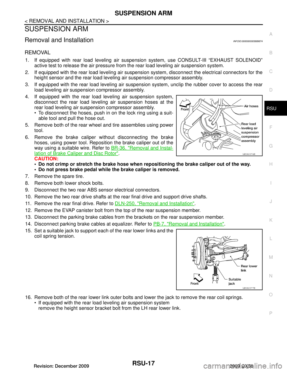
4. If equipped with the rear load leveling air suspension system, disconnect the rear load leveling air suspension hoses at the
rear load leveling air suspension compressor assembly.
To disconnect the hoses, push in on the lock ring using a suit-able tool and pull the hose out.
5. Remove both of the rear wheel and tire assemblies using power tool.
6. Remove the brake caliper without disconnecting the brake hoses, using power tool. Reposition the brake caliper out of the
way using a suitable wire. Refer to BR-36, "Removal and Instal-
lation of Brake Caliper and Disc Rotor".
CAUTION:
Do not crimp or stretch the brake hose when re positioning the brake caliper out of the way.
Do not press brake pedal while the brake caliper is removed.
7. Remove the spare tire.
8. Remove both lower shock bolts.
9. Disconnect the two rear ABS sensor electrical connectors.
10. Remove the two rear drive shafts at t he rear final drive and support drive shafts.
11. Remove the rear final drive. Refer to DLN-250, "Removal and Installation"
.
12. Remove the EVAP canister bolt from the top of the rear suspension member.
13. Disconnect the parking brake cables from t he brackets on the rear suspension member.
14. Disconnect parking brake cables at equalizer. Refer to PB-7, "Removal and Installation"
.
15. Set a suitable jack to support each of the rear lower links and the coil spring tension.
16. Remove both of the rear lower link outer bolts and lower the jack to remove the rear coil springs. If equipped with the rear load leveling air suspension systemremove the height sensor bracket bolt from the LH rear lower link.
LEIA0074E
LEIA0077E
Revision: December 20092009 QX56