Page 3740 of 4171
TM-92
< COMPONENT DIAGNOSIS >
MAIN POWER SUPPLY AND GROUND CIRCUIT
MAIN POWER SUPPLY AND GROUND CIRCUIT
Diagnosis ProcedureINFOID:0000000003771975
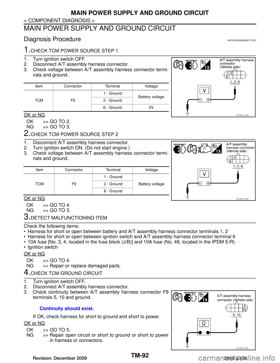
1.CHECK TCM POWER SOURCE STEP 1
1. Turn ignition switch OFF.
2. Disconnect A/T assembly harness connector.
3. Check voltage between A/T assembly harness connector termi- nals and ground.
OK or NG
OK >> GO TO 2.
NG >> GO TO 3.
2.CHECK TCM POWER SOURCE STEP 2
1. Disconnect A/T assembly harness connector.
2. Turn ignition switch ON. (Do not start engine.)
3. Check voltage between A/T assembly harness connector termi- nals and ground.
OK or NG
OK >> GO TO 4.
NG >> GO TO 3.
3.DETECT MALFUNCTIONING ITEM
Check the following items:
Harness for short or open between battery and A/T assembly harness connector terminals 1, 2
Harness for short or open between ignition switch and A/T assembly harness connector terminal 6
10A fuse [No. 3, 4, located in the fuse block (J /B)] and 10A fuse (No. 49, located in the IPDM E/R)
Ignition switch
OK or NG
OK >> GO TO 4.
NG >> Repair or replace damaged parts.
4.CHECK TCM GROUND CIRCUIT
1. Turn ignition switch OFF.
2. Disconnect A/T assembly harness connector.
3. Check continuity between A/T assembly harness connector F9 terminals 5, 10 and ground.
If OK, check harness for short to ground and short to power.
OK or NG
OK >> GO TO 5.
NG >> Repair open circuit or short to ground or short to power in harness or connectors.
Item Connector Terminal Voltage
TCM F9 1 - Ground
Battery voltage
2 - Ground
6 - Ground 0V
SCIA2104E
Item Connector Terminal Voltage
TCM F9 1 - Ground
Battery voltage
2 - Ground
6 - Ground
SCIA2105E
Continuity should exist.
SCIA2106E
Revision: December 20092009 QX56
Page 3741 of 4171
MAIN POWER SUPPLY AND GROUND CIRCUITTM-93
< COMPONENT DIAGNOSIS >
CEF
G H
I
J
K L
M A
B
TM
N
O P
5.DETECT MALFUNCTIONING ITEM
Check the following items:
The A/T assembly harness connector terminals for damage or loose connection with harness connector.
OK or NG
OK >> GO TO 6.
NG >> Repair or replace damaged parts.
6.PERFORM SELF-DIAGNOSIS
Perform self-diagnosis. Refer to TM-32, "CONSULT-III Function (TRANSMISSION)"
.
OK or NG
OK >> INSPECTION END
NG-1 >> Self-diagnosis does not activate: GO TO 7.
NG-2 >> DTC is displayed: Check t he malfunctioning system. Refer to TM-32, "CONSULT-III Function
(TRANSMISSION)".
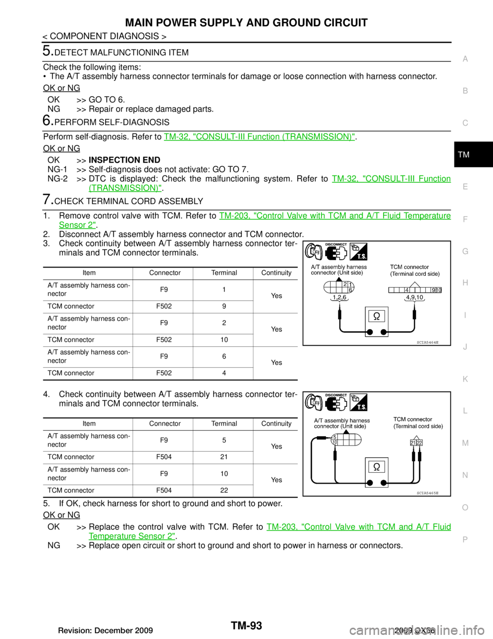
7.CHECK TERMINAL CORD ASSEMBLY
1. Remove control valve with TCM. Refer to TM-203, "Control Valve with TCM and A/T Fluid Temperature
Sensor 2".
2. Disconnect A/T assembly harness connector and TCM connector.
3. Check continuity between A/T assembly harness connector ter- minals and TCM connector terminals.
4. Check continuity between A/T assembly harness connector ter- minals and TCM connector terminals.
5. If OK, check harness for short to ground and short to power.
OK or NG
OK >> Replace the control valve with TCM. Refer to TM-203, "Control Valve with TCM and A/T Fluid
Temperature Sensor 2".
NG >> Replace open circuit or short to ground and short to power in harness or connectors.
Item Connector Terminal Continuity
A/T assembly harness con-
nector F9 1
Ye s
TCM connector F502 9
A/T assembly harness con-
nector F9 2
Ye s
TCM connector F502 10
A/T assembly harness con-
nector F9 6
Ye s
TCM connector F502 4
SCIA5464E
Item Connector Terminal Continuity
A/T assembly harness con-
nector F9 5
Ye s
TCM connector F504 21
A/T assembly harness con-
nector F9 10
Ye s
TCM connector F504 22
SCIA5465E
Revision: December 20092009 QX56
Page 3742 of 4171
TM-94
< COMPONENT DIAGNOSIS >
CLOSED THROTTLE POSITION AND WIDE OPEN THROTTLE POSITION CIR-
CUIT
CLOSED THROTTLE POSITION AND WIDE OPEN THROTTLE POSITION
CIRCUIT
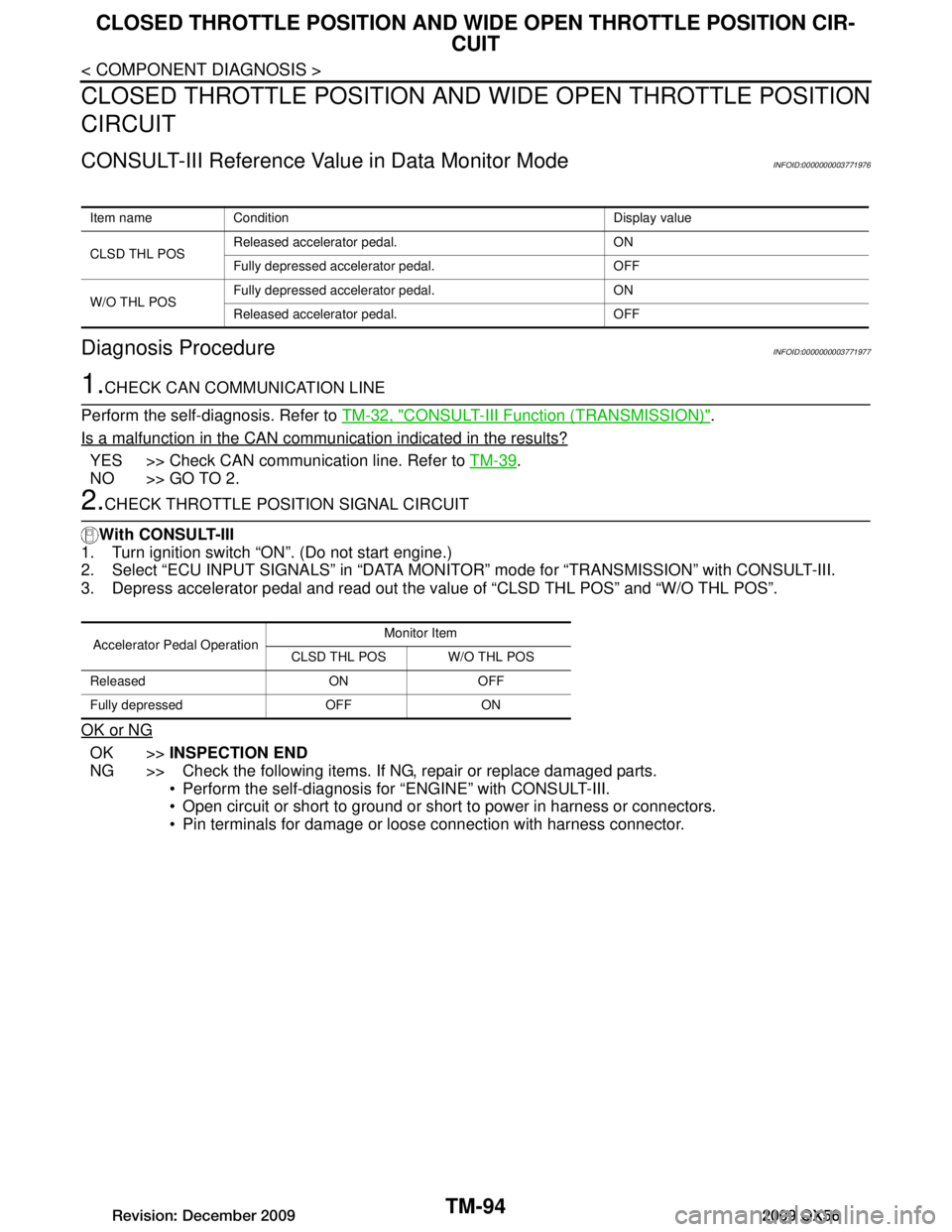
CONSULT-III Reference Value in Data Monitor ModeINFOID:0000000003771976
Diagnosis ProcedureINFOID:0000000003771977
1.CHECK CAN COMMUNICATION LINE
Perform the self-diagnosis. Refer to TM-32, "CONSULT-III Function (TRANSMISSION)"
.
Is a malfunction in the CAN communication indicated in the results?
YES >> Check CAN communication line. Refer to TM-39.
NO >> GO TO 2.
2.CHECK THROTTLE POSI TION SIGNAL CIRCUIT
With CONSULT-III
1. Turn ignition switch “ON”. (Do not start engine.)
2. Select “ECU INPUT SIGNALS” in “DATA MONI TOR” mode for “TRANSMISSION” with CONSULT-III.
3. Depress accelerator pedal and read out the value of “CLSD THL POS” and “W/O THL POS”.
OK or NG
OK >> INSPECTION END
NG >> Check the following items. If NG, repair or replace damaged parts. Perform the self-diagnosis for “ENGINE” with CONSULT-III.
Open circuit or short to ground or shor t to power in harness or connectors.
Pin terminals for damage or loos e connection with harness connector.
Item name Condition Display value
CLSD THL POSReleased accelerator pedal. ON
Fully depressed accelerator pedal. OFF
W/O THL POS Fully depressed accelerator pedal. ON
Released accelerator pedal. OFF
Accelerator Pedal Operation Monitor Item
CLSD THL POS W/O THL POS
Released ON OFF
Fully depressed OFF ON
Revision: December 20092009 QX56
Page 3743 of 4171
BRAKE SIGNAL CIRCUITTM-95
< COMPONENT DIAGNOSIS >
CEF
G H
I
J
K L
M A
B
TM
N
O P
BRAKE SIGNAL CIRCUIT
CONSULT-III Reference Val ue in Data Monitor ModeINFOID:0000000003771978
Diagnosis ProcedureINFOID:0000000003771979
1.CHECK CAN COMMUNICATION LINE
Perform the self-diagnosis. Refer to TM-32, "CONSULT-III Function (TRANSMISSION)"
.
Is a malfunction in the CAN communication indicated in the results?
YES >> Check CAN communication line. Refer to TM-39, "Diagnosis Procedure".
NO >> GO TO 2.
2.CHECK STOP LAMP SWITCH CIRCUIT
With CONSULT-III
1. Turn ignition switch “ON”. (Do not start engine.)
2. Select “ECU INPUT SIGNALS” in “DATA MONITO R” mode for “TRANSMISSION” with CONSULT-III.
3. Read out ON/OFF switching action of the “BRAKE SW”.
OK or NG
OK >> INSPECTION END
NG >> GO TO 3.
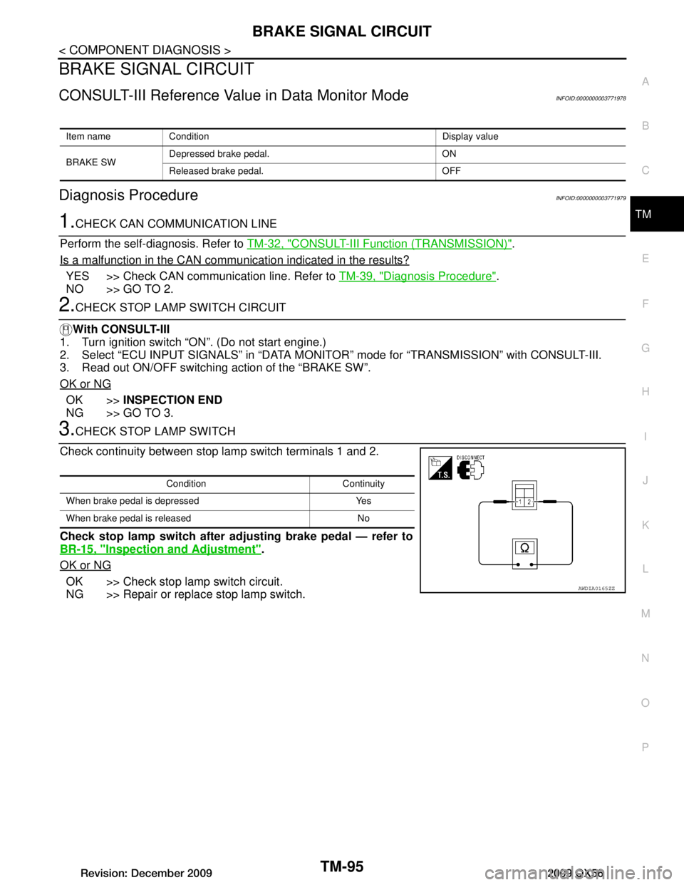
3.CHECK STOP LAMP SWITCH
Check continuity between stop lamp switch terminals 1 and 2.
Check stop lamp switch after adjusting brake pedal — refer to
BR-15, "Inspection and Adjustment"
.
OK or NG
OK >> Check stop lamp switch circuit.
NG >> Repair or replace stop lamp switch.
Item name Condition Display value
BRAKE SW Depressed brake pedal. ON
Released brake pedal. OFF
Condition Continuity
When brake pedal is depressed Yes
When brake pedal is released No
AWDIA0165ZZ
Revision: December 20092009 QX56
Page 3744 of 4171
TM-96
< COMPONENT DIAGNOSIS >
TOW MODE SWITCH
TOW MODE SWITCH
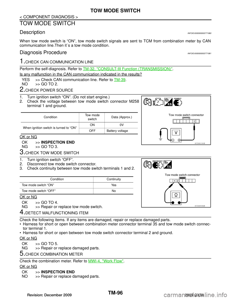
DescriptionINFOID:0000000003771980
When tow mode switch is “ON”, tow mode switch signals are sent to TCM from combination meter by CAN
communication line.Then it`s a tow mode condition.
Diagnosis ProcedureINFOID:0000000003771981
1.CHECK CAN COMMUNICATION LINE
Perform the self-diagnosis. Refer to TM-32, "CONSULT-III Function (TRANSMISSION)"
.
Is any malfunction in the CAN communication indicated in the results?
YES >> Check CAN communication line. Refer to TM-39.
NO >> GO TO 2.
2.CHECK POWER SOURCE
1. Turn ignition switch “ON”. (Do not start engine.)
2. Check the voltage between tow mode switch connector M258 terminal 1 and ground.
OK or NG
OK >> INSPECTION END
NG >> GO TO 3.
3.CHECK TOW MODE SWITCH
1. Turn ignition switch “OFF”.
2. Disconnect tow mode switch connector.
3. Check continuity between tow mode switch terminals 1 and 2.
OK or NG
OK >> GO TO 4.
NG >> Repair or replace tow mode switch.
4.DETECT MALFUNCTIONING ITEM
Check the following items. If any items are damaged, repair or replace damaged parts.
Harness for short or open between combination meter connector terminal 35 and tow mode switch connec- tor terminal 1.
Harness for short or open between tow mode switch connector terminal 2 and ground.
OK or NG
OK >> GO TO 5.
NG >> Repair or replace damaged parts.
5.CHECK COMBINATION METER
Check the combination meter. Refer to MWI-4, "Work Flow"
.
OK or NG
OK >> INSPECTION END
NO >> Repair or replace damaged parts.
Condition To w m o d e
switch Data (Approx.)
When ignition switch is turned to “ON” ON 0V
OFF Battery voltage
SCIA5156E
Condition Continuity
Tow mode switch “ON” Yes
Tow mode switch “OFF” No
SCIA5584E
Revision: December 20092009 QX56
Page 3745 of 4171
A/T SHIFT LOCK SYSTEMTM-97
< COMPONENT DIAGNOSIS >
CEF
G H
I
J
K L
M A
B
TM
N
O P
A/T SHIFT LOCK SYSTEM
Wiring Diagram - A/ T Shift Lock SystemINFOID:0000000003771982
AADWA0090GB
Revision: December 20092009 QX56
Page 3746 of 4171
TM-98
< COMPONENT DIAGNOSIS >
A/T SHIFT LOCK SYSTEM
AADIA0061GB
Revision: December 20092009 QX56
Page 3747 of 4171
A/T SHIFT LOCK SYSTEMTM-99
< COMPONENT DIAGNOSIS >
CEF
G H
I
J
K L
M A
B
TM
N
O P
AADIA0141GB
Revision: December 20092009 QX56