Page 3596 of 4171
PREPARATIONST-5
< PREPARATION >
C
DE
F
H I
J
K L
M A
B
ST
N
O P
PREPARATION
PREPARATION
Special Service ToolINFOID:0000000003775117
The actual shapes of Kent-Moore tools may differ fr om those of special service tools illustrated here.
Tool number
(Kent-Moore No.)
Tool name Description
HT72520000
(J-25730-A)
Ball joint remover Removing ball joint
KV40107300
(—)
Band clamp pliers Crimping boot clamps
1. KV48105300-4 and 5295262U10
(—
Connector A and O-ring
2. KV48105300-3 and 5295262U00
(—)
Eye-bolt and O-ring
3. KV48103500
(J-26357 and J-26357-10)
Pressure gauge and shut-off valve
4. KV48105300-1 and 5295262U00
(—)
Connector B and O-ring
5. KV48105300-2 —— )
Nut Measuring oil pump relief pressure
ST27180001
(J-25726-A)
Steering wheel puller Removing steering wheel
NT146
ZZA1229D
SGIA0427E
ZZA0819D
Revision: December 20092009 QX56
Page 3597 of 4171
ST-6
< PREPARATION >
PREPARATION
Commercial Service Tool
INFOID:0000000003775118
ST3127S000
(J-25765-A)
Preload gauge
1. GG9103000
(J-25765-A)
Torque wrench
2. HT62940000
(—)
Socket adapter
3. HT62900000
(—)
Socket adapter Inspecting sliding torque, steering torque and
rotating torque for ball joint
(—)
J-44372
Spring gauge Measure steering wheel turning force or rack
sliding force
Tool number
(Kent-Moore No.)
Tool name
Description
S-NT541
LST024
Tool name
Description
Power tool Removing nuts and bolts
PBIC0190E
Revision: December 20092009 QX56
Page 3598 of 4171

HEATED STEERING WHEELST-7
< FUNCTION DIAGNOSIS >
C
DE
F
H I
J
K L
M A
B
ST
N
O P
FUNCTION DIAGNOSIS
HEATED STEERING WHEEL
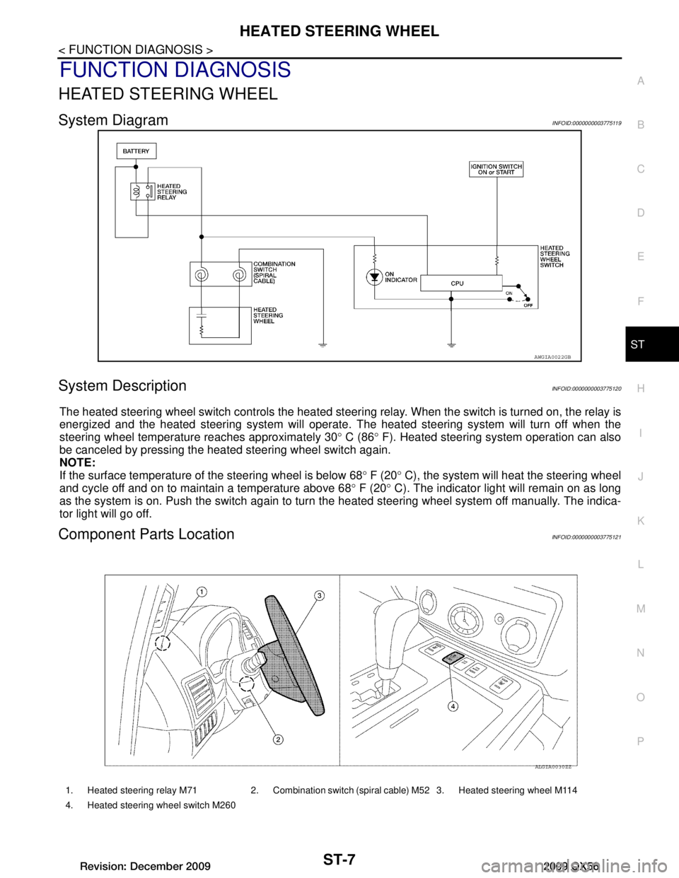
System DiagramINFOID:0000000003775119
System DescriptionINFOID:0000000003775120
The heated steering wheel switch controls the heated steeri ng relay. When the switch is turned on, the relay is
energized and the heated steering system will operate. T he heated steering system will turn off when the
steering wheel temperature reaches approximately 30 ° C (86 ° F). Heated steering system operation can also
be canceled by pressing the heated steering wheel switch again.
NOTE:
If the surface temperature of the steering wheel is below 68 ° F (20 ° C), the system will heat the steering wheel
and cycle off and on to maintain a temperature above 68 ° F (20 ° C). The indicator light will remain on as long
as the system is on. Push the switch again to turn the heated steering wheel system off manually. The indica-
tor light will go off.
Component Parts LocationINFOID:0000000003775121
AWGIA0022GB
1. Heated steering relay M71 2. Combination switch (spiral cable) M52 3. Heated steering wheel M114
4. Heated steering wheel switch M260
ALGIA0030ZZ
Revision: December 20092009 QX56
Page 3599 of 4171
ST-8
< FUNCTION DIAGNOSIS >
HEATED STEERING WHEEL
Component Description
INFOID:0000000003775122
Heated steering wheel switch Controls the heated steering relay and operates the heated steering system.
Turns the indicator lamp ON when the system is activated.
Heated steering relay Operates the heated steering system with the control signal from the heated steering
wheel switch.
Heated steering wheel Heats the heating element with the power supplied from the heated steering relay.
Revision: December 20092009 QX56
Page 3600 of 4171
HEATED STEERING WHEELST-9
< COMPONENT DIAGNOSIS >
C
DE
F
H I
J
K L
M A
B
ST
N
O P
COMPONENT DIAGNOSIS
HEATED STEERING WHEEL
Wiring DiagramINFOID:0000000003775123
ABGWA0003GB
Revision: December 20092009 QX56
Page 3601 of 4171
ST-10
< COMPONENT DIAGNOSIS >
HEATED STEERING WHEEL
ABGIA0004GB
Revision: December 20092009 QX56
Page 3602 of 4171
HEATED STEERING WHEELST-11
< COMPONENT DIAGNOSIS >
C
DE
F
H I
J
K L
M A
B
ST
N
O P
ABGIA0005GB
Revision: December 20092009 QX56
Page 3603 of 4171

ST-12
< SYMPTOM DIAGNOSIS >
NOISE, VIBRATION AND HARSHNESS (NVH) TROUBLESHOOTING
SYMPTOM DIAGNOSIS
NOISE, VIBRATION AND HARSHNESS (NVH) TROUBLESHOOTING
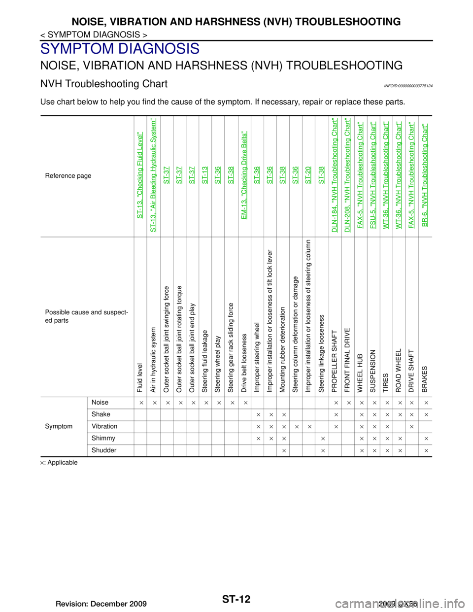
NVH Troubleshooting ChartINFOID:0000000003775124
Use chart below to help you find the cause of the symp tom. If necessary, repair or replace these parts.
×: ApplicableReference page
ST-13, "Checking Fluid Level"
ST-13, "Air Bleeding Hydraulic System"
ST-37ST-37ST-37ST-13ST-36ST-38
EM-13, "Checking Drive Belts"
ST-36ST-36ST-38ST-36ST-20ST-38
DLN-184, "NVH Troubleshooting Chart"DLN-208, "NVH Troubleshooting Chart"FAX-5, "NVH Troubleshooting Chart"FSU-5, "NVH Troubleshooting Chart"WT-36, "NVH Troubleshooting Chart"WT-36, "NVH Troubleshooting Chart"FAX-5, "NVH Troubleshooting Chart"BR-6, "NVH Troubleshooting Chart"
Possible cause and suspect-
ed parts
Fluid level
Air in hydraulic system
Outer socket ball joint swinging force
Outer socket ball joint rotating torque
Outer socket ball joint end play
Steering fluid leakage
Steering wheel play
Steering gear rack sliding force
Drive belt looseness
Improper steering wheel
Improper installation or looseness of tilt lock lever
Mounting rubber deterioration
Steering column deformation or damage
Improper installation or looseness of steering column
Steering linkage looseness
PROPELLER SHAFT
FRONT FINAL DRIVE
WHEEL HUB
SUSPENSION
TIRES
ROAD WHEEL
DRIVE SHAFT
BRAKES
Symptom
Noise
× × ××××× × × ××××××× ×
Shake ××× × ××××× ×
Vibration ××××× × ××× ×
Shimmy ××× × ×××× ×
Shudder × × ×××× ×
Revision: December 20092009 QX56