2009 INFINITI QX56 reset
[x] Cancel search: resetPage 2746 of 4171
MWI-24
< FUNCTION DIAGNOSIS >
DIAGNOSIS SYSTEM (METER)
DIAGNOSIS SYSTEM (METER)
Diagnosis DescriptionINFOID:0000000003776626
SELF-DIAGNOSIS MODE
The following items can be checked during Combination Meter Self-Diagnosis Mode.
• Gauge sweep and present gauge values.
• Illuminates all odometer/trip meters and A/T indicator segments.
• Illuminates all micro controlled lamps/LEDs regardless of switch position.
• Displays estimated present battery voltage.
• Displays seat belt buckle switch LH status.
OPERATION PROCEDURE
NOTE:
• Once entered, combination meter self-diagnosis mode will function with the ignition switch in ON or START.
Combination meter self-diagnosis mode will exit upon turning the ignition switch to OFF or ACC.
• If the diagnosis function is activated with trip A displa yed, the mileage on trip A is reset to 0000.0. (Trip B
operates the same way.)
To initiate combination meter self-diagnosis mode, refer to the following procedure.
1. Turn the ignition switch ON, while pressing the odometer/trip meter switch for 5 - 8 \
seconds. When the diagnosis function is activated, the odometer/trip meter will display tESt.
NOTE:
Check combination meter power supply and ground circuit when self-diagnosis mode of combination meter
does not start. Refer to MWI-30, "
COMBINATION METER : Diagnosis Procedure". Replace combination
meter if normal. Refer to MWI-102, "
Removal and Installation".
COMBINATION METER SELF-DIAGNOSIS MODE FUNCTIONS
To interpret combination meter self-diagnosis mode functions, refer to the following table.
EventOdometer Display Description of Test/Data Notes:
Odometer/trip meter A/B
switch held from 5 to 8
seconds (or until re-
leased) tESt
Initiating self-diagnosis mode
Switch released GAGE Performs sweep of all
gauges, then displays
present gauge values.Gauges sweep within 10 seconds
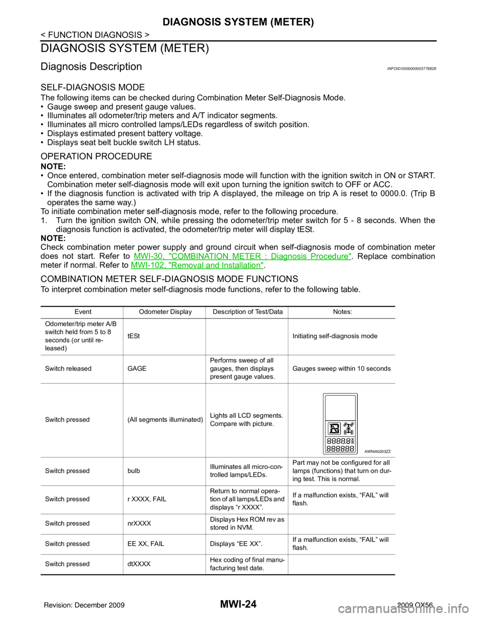
Switch pressed (All segments illuminated) Lights all LCD segments.
Compare with picture.
Switch pressed bulbIlluminates all micro-con-
trolled lamps/LEDs. Part may not be configured for all
lamps (functions) th
at turn on dur-
ing test. This is normal.
Switch pressed r XXXX, FAIL Return to normal opera-
tion of all lamps/LEDs and
displays “r XXXX”.If a malfunction exists, “FAIL” will
flash.
Switch pressed nrXXXX Displays Hex ROM rev as
stored in NVM.
Switch pressed EE XX, FAIL Displays “EE XX”.If a malfunction exists, “FAIL” will
flash.
Switch pressed dtXXXX Hex coding of final manu-
facturing test date.
AWNIA0203ZZ
Revision: December 20092009 QX56
Page 2879 of 4171
PG-8
< BASIC INSPECTION >
INSPECTION AND ADJUSTMENT
INSPECTION AND ADJUSTMENT
ADDITIONAL SERVICE WHEN REMOVING BATTERY NEGATIVE TERMINAL
ADDITIONAL SERVICE WHEN REMOVING BATTERY NEGATIVE TERMINAL : Spe-
cial Repair Requirement
INFOID:0000000005864655
Required Procedure After Battery Disconnection
System ItemReference
Engine Control Idle Air Volume Learning Refer to EC-18
.
Brake Control Steering Angle Sensor Neutral Position Refer to BRC-8
.
Glasses, Window and Mirrors Power Window System Initialization Refer to TSB.
Body, Lock & Security Automatic Back Door Initialization Refer to DLK-9
.
Roof Sunroof Memory Reset/Initialization Refer to RF-5
.
Seats Automatic Drive Positioner System Initialization Refer to Owner's Manual.
Audio-Visual System Audio (Radio Preset)
Refer to Owner's Manual.
Navigation System Refer to Owner's Manual.
Rear View Monitor Guiding Line Adjustment Refer to AV- 7
.
Revision: December 20092009 QX56
Page 2947 of 4171
PG-76
< ON-VEHICLE REPAIR >
BATTERY
ON-VEHICLE REPAIR
BATTERY
Removal and InstallationINFOID:0000000003776577
REMOVAL
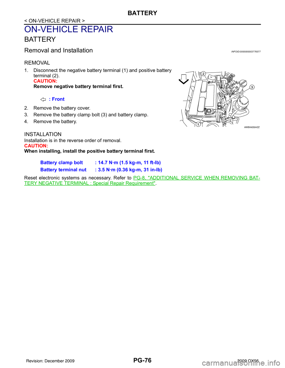
1. Disconnect the negative battery terminal (1) and positive batteryterminal (2).
CAUTION:
Remove negative battery terminal first.
2. Remove the battery cover.
3. Remove the battery clamp bolt (3) and battery clamp.
4. Remove the battery.
INSTALLATION
Installation is in the reverse order of removal.
CAUTION:
When installing, install the po sitive battery terminal first.
Reset electronic systems as necessary. Refer to PG-8, "
ADDITIONAL SERVICE WHEN REMOVING BAT-
TERY NEGATIVE TERMINAL : Special Repair Requirement".
: Front
AWBIA0504ZZ
Battery clamp bolt : 14.7 N·m (1.5 kg-m, 11 ft-lb)
Battery terminal nut : 3.5 N·m (0.36 kg-m, 31 in-lb)
Revision: December 20092009 QX56
Page 3096 of 4171

INSPECTION AND ADJUSTMENTRF-5
< BASIC INSPECTION >
C
DE
F
G H
I
J
L
M A
B
RF
N
O P
INSPECTION AND ADJUSTMENT
ADDITIONAL SERVICE WHEN REPLACING CONTROL UNIT
ADDITIONAL SERVICE WHEN REPL ACING CONTROL UNIT : Description
INFOID:0000000003776061
MEMORY RESET PROCEDURE
1. Please observe the following instructi ons at confirming the sunroof operation.
NOTE:
Do not disconnect the electronic power while the sunroof is operating or within 5 seconds after the sunroof
stops. (to wipe-out the memory of lid position and operating friction.)
2. Initialization of system should be conducted after the following conditions.
• When the sunroof motor is changed.
• When the sunroof does not operate normally. (Incomplete initialization conditions)
ADDITIONAL SERVICE WHEN REPLACING CONTROL UNIT : Special Repair Re-
quirement
INFOID:0000000003776062
INITIALIZATION PROCEDURE
If the sunroof does not close or open automatically, us e the following procedure to return sunroof operation to
normal.
1. Turn ignition switch ON.
2. Push and hold the sunroof tilt switch in the forw ard (DOWN) position until the sunroof is fully closed.
3. After the sunroof has closed all the way, push and hold the tilt switch forward (DOWN) again for more than 2 seconds to re-learn motor position.
4. Initialization is complete if the sunroof operates normally.
BASIC INSPECTION
BASIC INSPECTION : Special Repair RequirementINFOID:0000000003776063
BASIC INSPECTION
1.INSPECTION START
1. Check the service history.
2. Check the following parts.
• Fuse/circuit breaker blown.
• Poor connection, open or short circuit of harness connector.
• Battery voltage.
Is the inspection result normal?
YES >> Inspection End.
NO >> Repair or replace the malfunctioning parts.
Revision: December 20092009 QX56
Page 3148 of 4171
SUNROOF SYSTEMRF-57
< ON-VEHICLE REPAIR >
C
DE
F
G H
I
J
L
M A
B
RF
N
O P
Removal
CAUTION:
• When removing the sunroof motor, be sure to
place the link and wire assembly in the symmetrical
and fully closed position.
• Never run the removed sunroof motor assembly as a single unit.
1. Position the sunroof in the fully closed position.
2. Remove the roof console assembly. Refer to INT-17, "
Removal and Installation".
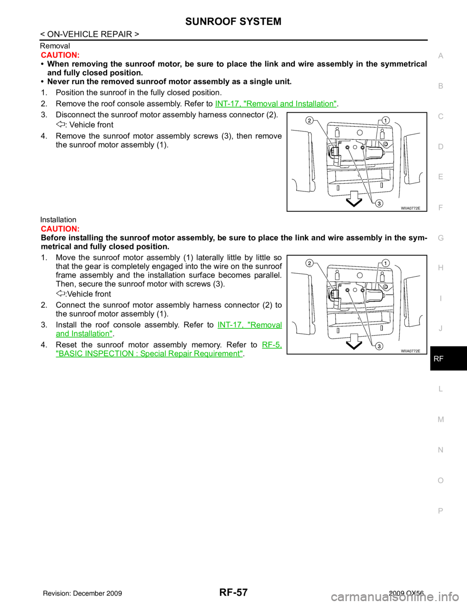
3. Disconnect the sunroof motor assembly harness connector (2). : Vehicle front
4. Remove the sunroof motor assembly screws (3), then remove the sunroof motor assembly (1).
Installation
CAUTION:
Before installing the sunroof motor assembly, be sure to place the link and wire assembly in the sym-
metrical and fully closed position.
1. Move the sunroof motor assembly (1) laterally little by little sothat the gear is completely engaged into the wire on the sunroof
frame assembly and the installation surface becomes parallel.
Then, secure the sunroof motor with screws (3).
:Vehicle front
2. Connect the sunroof motor assembly harness connector (2) to the sunroof motor assembly (1).
3. Install the roof console assembly. Refer to INT-17, "
Removal
and Installation".
4. Reset the sunroof motor assembly memory. Refer to RF-5,
"BASIC INSPECTION : Special Repair Requirement".
WIIA0772E
WIIA0772E
Revision: December 20092009 QX56
Page 3200 of 4171

DIAGNOSIS SYSTEM (SUSPENSION CONTROL UNIT)
SCS-7
< FUNCTION DIAGNOSIS >
C
D F
G H
I
J
K L
M A
B
SCS
N
O P
DIAGNOSIS SYSTEM (SUS PENSION CONTROL UNIT)
CONSULT-III FunctionINFOID:0000000003772311
CONSULT-III can display each diagnostic item using the diagnostic test modes shown following.
WORK SUPPORT
Display Item List
DATA MONITOR
Display Item List
ACTIVE TEST
CAUTION:
Do not perform active test while driving.
Display Item List
AIR LEVELIZER diagnosis mode Description
WORK SUPPORT Supports inspection and adjustment. Commands are transmitted to the suspension control
unit for setting the status suitable for required operation, input/output signals are received
from the suspension control unit and received data is displayed.
SELF-DIAG RESULTS Displays suspension control unit self-diagnosis results.
DATA MONITOR Displays suspension control unit input/output data in real time.
ACTIVE TEST Operation of electrical loads can be checked by sending drive signal to them.
ECU PART NUMBER The part number of suspension control unit can be checked.
ItemDescription Condition
STANDARD HEIGHT LEVEL Resets the vehicle height to the initialization flag
setting stored in the suspension control unit. Vehicle unladen, set in a horizontal position and
not moving.
NOTE:
Do not take your eyes off the vehicle while CON-
SULT-III is processing.
ADJUST HEIGHT INI Sets the height initialization flag in the suspen-
sion control unit when the control unit has been
replaced or when the initialization flag has been
cleared using the "CLEAR HEIGHT INI" proce-
dure. Vehicle unladen, move vehicle forward and back-
ward approx. 5 m (16.4 ft) and rock vehicle side
to side.
NOTE:
Do not move vehicle wh
ile CONSULT-III is pro-
cessing.
CLEAR HEIGHT INI Clears the initialization flag in the suspension
control unit. Vehicle unladen.
Display item [unit] ALL
SIGNALS SELECTION FROM MENU
HEIGT SEN [V] XX
HEIGT CALC [mm] XX
SEN FIX TIME [HR] XX
HEIGT INI VAL [V] XX
COMPRESSOR [ON/OFF] XX
EXH SOLENOID [ON/OFF] XX
ACG L [ON/OFF] XX
Test Item Description
COMPRESSOR ON/OFF
Revision: December 20092009 QX56
Page 3431 of 4171
SN
REAR SONAR SYSTEMSN-9
< FUNCTION DIAGNOSIS >
C
DE
F
G H
I
J
K L
M B A
O P
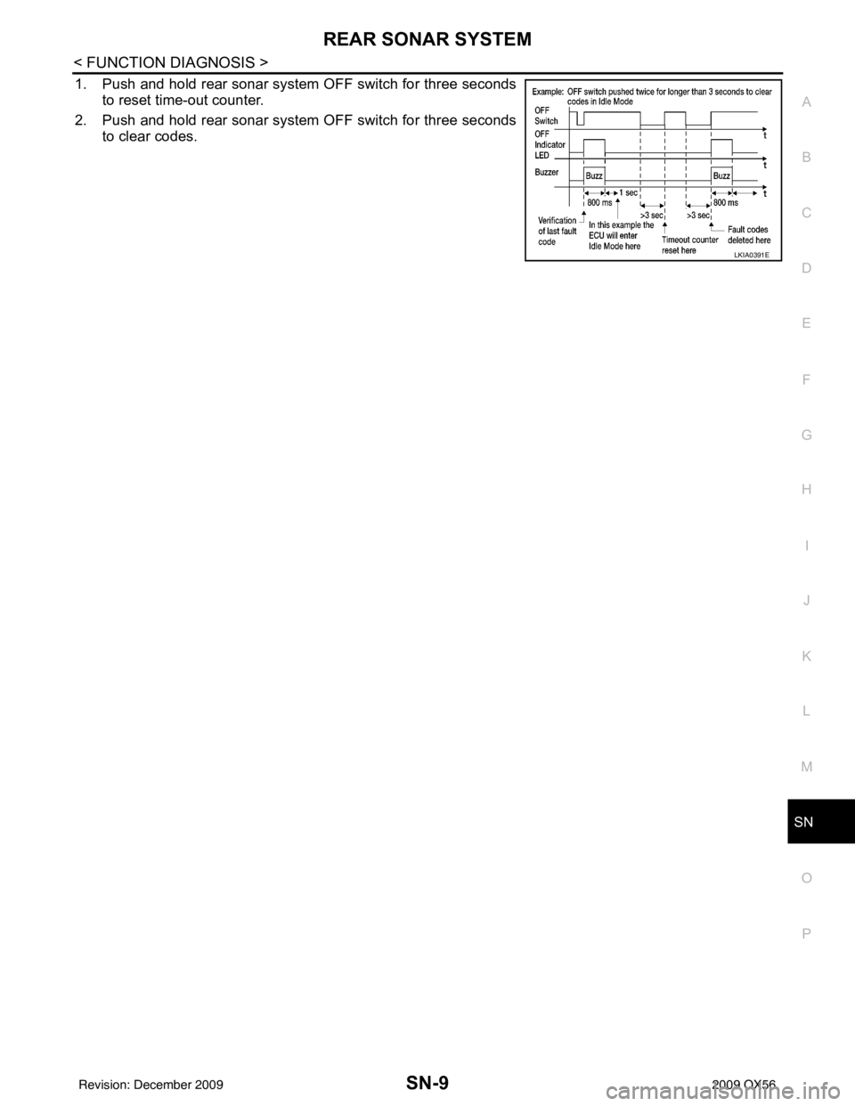
1. Push and hold rear sonar system OFF switch for three seconds
to reset time-out counter.
2. Push and hold rear sonar system OFF switch for three seconds
to clear codes.
LKIA0391E
Revision: December 20092009 QX56
Page 3513 of 4171
ON BOARD DIAGNOSTIC (OBD) SYSTEMSRC-15
< FUNCTION DIAGNOSIS >
C
DE
F
G
I
J
K L
M A
B
SRC
N
O P
Trouble Diagnosis without CONSULT-IIIINFOID:0000000003775186
DIAGNOSTIC PROCEDURE 6
Inspect SRS Malfunction Using "AIR BAG" Warning Lamp—Diagnosis Mode
NOTE:
SRS will not enter Diagnosis mode if no malfunction is detected in User mode.
1. Turn ignition switch ON.
2. After “AIR BAG” warning lamp lights for 7 seconds, turn ignition switch OFF within 1 second.
3. Wait more than 3 seconds.
4. Repeat steps 1 to 3 two more times (3 times total).
5. Turn ignition switch ON.
SRS is now in Diagnosis mode. Refer to SRC-85, "
Trouble Diagnosis without CONSULT-III".
CONSULT-III Function (AIR BAG)INFOID:0000000003775187
CONSULT-III can display each diagnostic item using the diagnostic test modes shown following.
Self-Diagnosis Function (Without CONSULT-III)INFOID:0000000003775188
• The reading of these results is accomplished using one of two modes — “User mode” and “Diagnosis
mode”.
• After a malfunction is repaired, turn the ignition s witch OFF for at least one second, then back ON. Diagnosis
mode returns to the User mode. At that time, the self-diagnostic result is cleared.
AIR BAG diagnostic mode Description
SELF-DIAG [CURRENT] A current Self-diagnosis result (also indicated by the number of warning lamp flashes in the Diagnosis
mode) is displayed on the CONSULT-III screen in real
time. This refers to a malfunctioning part requir-
ing repairs.
SELF-DIAG [PAST] Diagnosis results previously stored in the memo
ry are displayed on the CONSULT-III screen. The
stored results will remain until memory erasing is executed.
TROUBLE DIAG RECORD With TROUBLE DIAG RECORD, diagnosis results previously erased by a reset operation can be dis-
played on the CONSULT-III screen.
ECU DISCRIMINATED NO. Air bag diagnosis sensor unit ECU discriminated number (identification number) is displayed. Air bag
diagnosis sensor unit has individual ECU discriminated number (identification number) based on model
and equipment.
PASSENGER AIR BAG The STATUS (readiness) of the front passenger air bag module is displayed. The STATUS displayed
(ON/OFF) depends on the signals supplied to the occupant classification system control module and
air bag diagnosis sensor unit. Refer to
SRC-10, "
Occupant Classification System (OCS)" for more in-
formation.
Revision: December 20092009 QX56