Page 2925 of 4171
PG-54
< COMPONENT DIAGNOSIS >
HARNESS
BODY HARNESS
ABMIA0158GB
G3 B3 W/16 : Suspension control unitA4 B69 SMJ : To M40
E4 B6 W/18 : To D201 G2 B70 B/3 : Rear combination lamp LH
C5 B7 — : Body ground D5 B72 BR/6 : Subwoofer
D4 B8 W/3 : Front door switch LH F3 B73 W/16 : Rear view camera control unit
C4 B9 Y/12 : Air bag diagnosis sensor unit C4 B74 Y/4: Seat belt buckle pretensioner assembly
LH (seatbelt buckle switch)
Revision: December 20092009 QX56
Page 3080 of 4171

NOISE, VIBRATION AND HARSHNESS (NVH) TROUBLESHOOTINGRAX-5
< SYMPTOM DIAGNOSIS >
CEF
G H
I
J
K L
M A
B
RAX
N
O P
SYMPTOM DIAGNOSIS
NOISE, VIBRATION AND HARSHN ESS (NVH) TROUBLESHOOTING
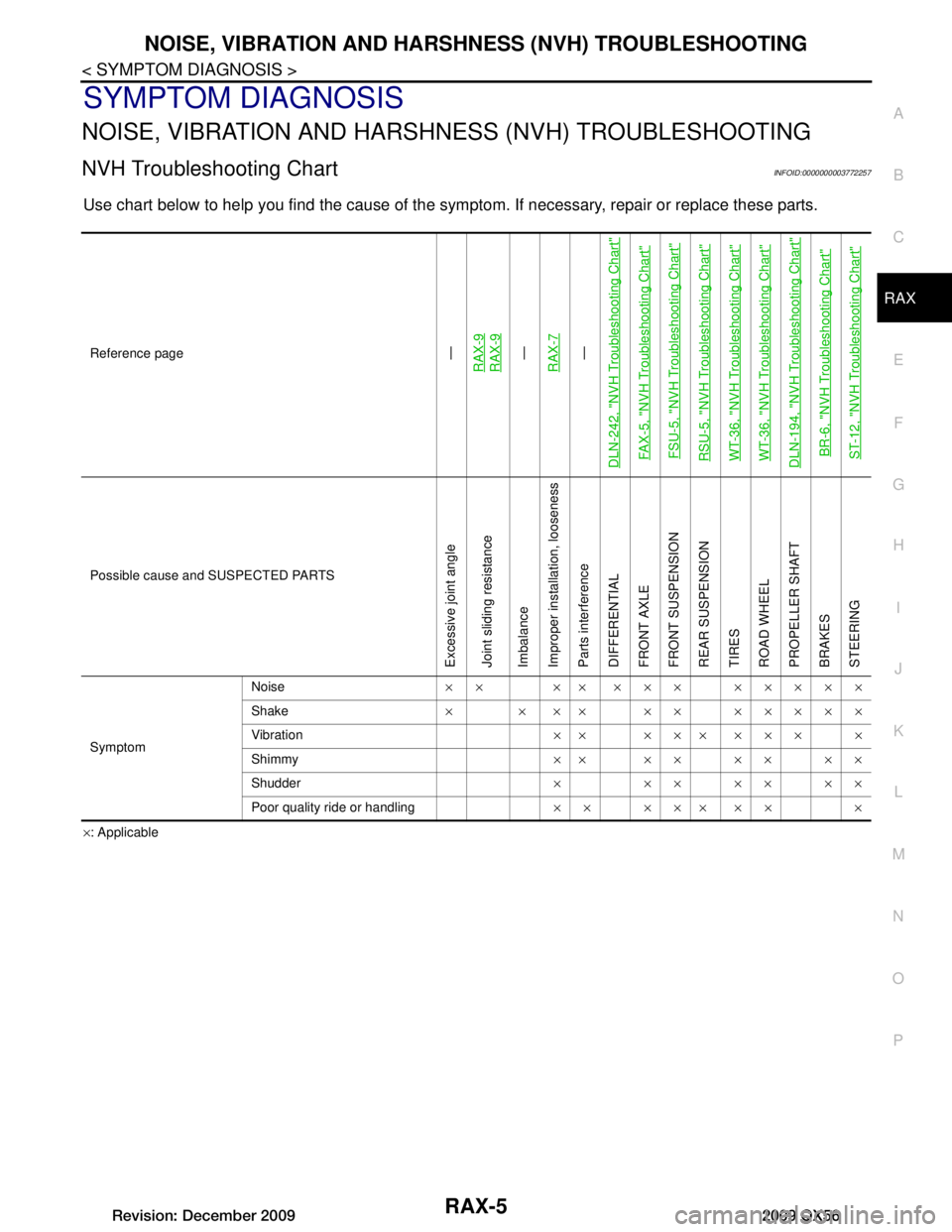
NVH Troubleshooting ChartINFOID:0000000003772257
Use chart below to help you find the cause of the symp tom. If necessary, repair or replace these parts.
×: Applicable
Reference page
—
RAX-9RAX-9—
RAX-7—
DLN-242, "NVH Troubleshooting Chart"
FAX-5, "NVH Troubleshooting Chart" FSU-5, "NVH Troubleshooting Chart"RSU-5, "NVH Troubleshooting Chart"WT-36, "NVH Troubleshooting Chart"WT-36, "NVH Troubleshooting Chart"DLN-194, "NVH Troubleshooting Chart"BR-6, "NVH Troubleshooting Chart"ST-12, "NVH Troubleshooting Chart"
Possible cause and SUSPECTED PARTS
Excessive joint angle
Joint sliding resistance
Imbalance
Improper installation, looseness
Parts interference
DIFFERENTIAL
FRONT AXLE
FRONT SUSPENSION
REAR SUSPENSION
TIRES
ROAD WHEEL
PROPELLER SHAFT
BRAKES
STEERING
Symptom Noise
×× ×× ××× ×××××
Shake × × ×× ×× ×××××
Vibration ×× ××× ××× ×
Shimmy ×× ×× ×× ××
Shudder × ××××××
Poor quality ride or handling ×× ××× ×× ×
Revision: December 20092009 QX56
Page 3149 of 4171

RSU-1
SUSPENSION
C
DF
G H
I
J
K L
M
SECTION RSU
A
B
RSU
N
O PCONTENTS
REAR SUSPENSION
PRECAUTION ................ ...............................2
PRECAUTIONS .............................................. .....2
Precaution for Supplemental Restraint System
(SRS) "AIR BAG" and "SEAT BELT PRE-TEN-
SIONER" ............................................................. ......
2
Precaution Necessary for Steering Wheel Rota-
tion After Battery Disconnect .....................................
2
PREPARATION ............................................4
PREPARATION .............................................. .....4
Special Service Tool ........................................... ......4
Commercial Service Tool ..........................................4
SYMPTOM DIAGNOSIS ...............................5
NOISE, VIBRATION AND HARSHNESS
(NVH) TROUBLESHOOTING ........................ .....
5
NVH Troubleshooting Chart ................................ ......5
ON-VEHICLE MAINTENANCE .....................6
REAR SUSPENSION ASSEMBLY ................ .....6
On-Vehicle Inspection and Service ..................... ......6
Wheel AlignmentInspection .......................................6
ON-VEHICLE REPAIR ..................................9
REAR SUSPENSION ASSEMBLY ................ .....9
Component .......................................................... ......9
REMOVAL AND INSTALLATION ...............11
REAR SUSPENSION MEMBER .................... ....11
Removal and Installation ..................................... ....11
SHOCK ABSORBER ........................................15
Removal and Installation ..................................... ....15
Disposal ...................................................................15
SUSPENSION ARM ..........................................17
Removal and Installation .........................................17
FRONT LOWER LINK .......................................19
Removal and Installation .........................................19
REAR LOWER LINK & COIL SPRING .............21
Removal and Installation .........................................21
STABILIZER BAR .............................................23
Removal and Installation .........................................23
REAR LOAD LEVELING AIR SUSPENSION
COMPRESSOR ASSEMBLY ............................
24
Removal and Installation .........................................24
CONTROL UNIT ................................................26
Removal and Installation .........................................26
Initialization Procedure ............................................26
HEIGHT SENSOR .............................................27
Removal and Installation .........................................27
SERVICE DATA AND SPECIFICATIONS
(SDS) ............... .............................................
29
SERVICE DATA AND SPECIFICATIONS
(SDS) .................................................................
29
Wheel Alignment (Unladen*1) ............................. ....29
Ball Joint ..................................................................29
Wheelarch Height (Unladen*1) ................................30
Revision: December 20092009 QX56
Page 3153 of 4171

NOISE, VIBRATION AND HARSHNESS (NVH) TROUBLESHOOTINGRSU-5
< SYMPTOM DIAGNOSIS >
C
DF
G H
I
J
K L
M A
B
RSU
N
O P
SYMPTOM DIAGNOSIS
NOISE, VIBRATION AND HARSHN ESS (NVH) TROUBLESHOOTING
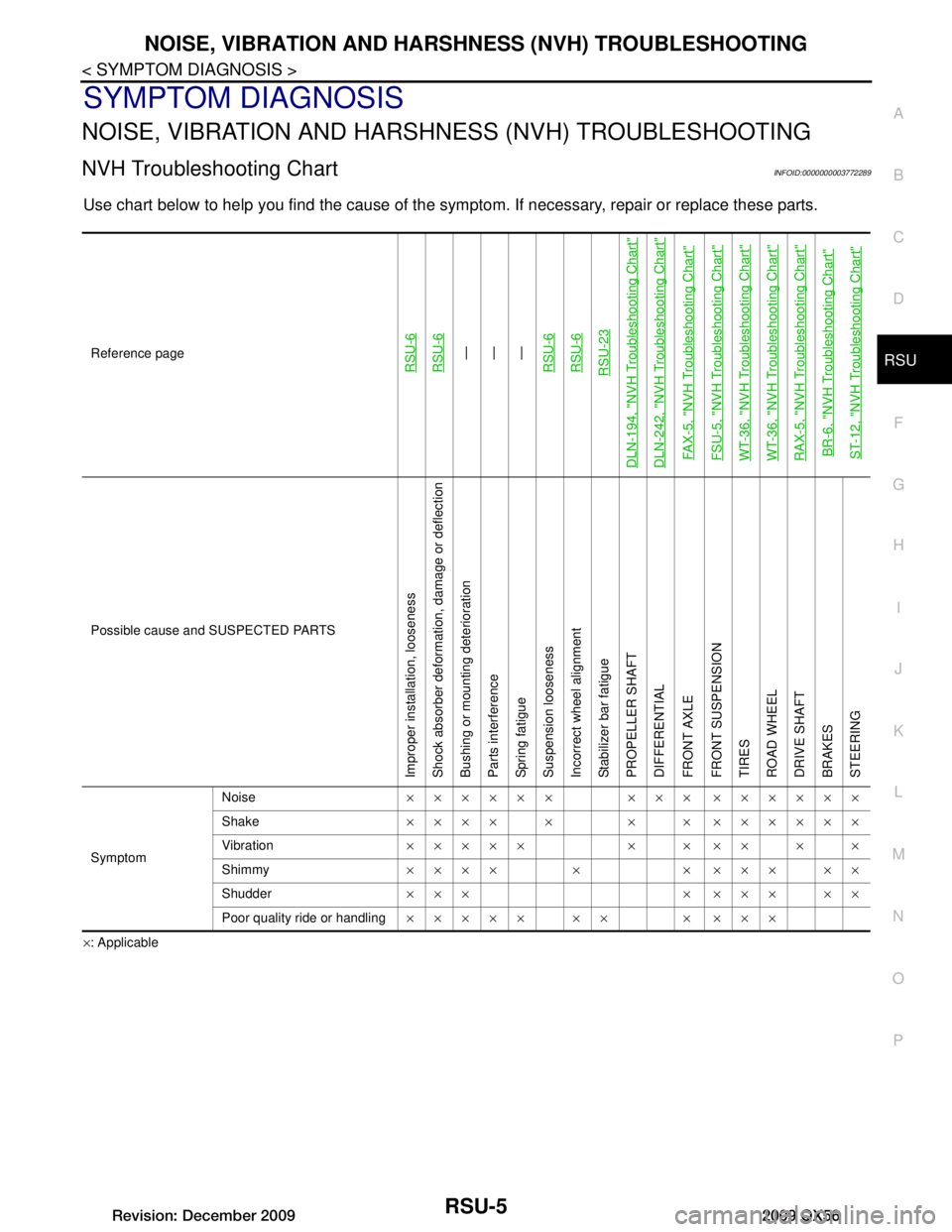
NVH Troubleshooting ChartINFOID:0000000003772289
Use chart below to help you find the cause of the symp tom. If necessary, repair or replace these parts.
×: ApplicableReference page
RSU-6RSU-6—
—
—
RSU-6RSU-6RSU-23
DLN-194, "NVH Troubleshooting Chart"DLN-242, "NVH Troubleshooting Chart"FAX-5, "NVH Troubleshooting Chart"FSU-5, "NVH Troubleshooting Chart"WT-36, "NVH Troubleshooting Chart"WT-36, "NVH Troubleshooting Chart"RAX-5, "NVH Troubleshooting Chart"BR-6, "NVH Troubleshooting Chart"ST-12, "NVH Troubleshooting Chart"
Possible cause and SUSPECTED PARTS
Improper installation, looseness
Shock absorber deformation, damage or deflection
Bushing or mounting deterioration
Parts interference
Spring fatigue
Suspension looseness
Incorrect wheel alignment
Stabilizer bar fatigue
PROPELLER SHAFT
DIFFERENTIAL
FRONT AXLE
FRONT SUSPENSION
TIRES
ROAD WHEEL
DRIVE SHAFT
BRAKES
STEERING
Symptom Noise
×××××× ××× ××××××
Shake ×××× × × × ××××××
Vibration ××××× × × ×× × ×
Shimmy ×××× × × ××× ××
Shudder ××× × ××× ××
Poor quality ride or handling ××××× ×× × ×××
Revision: December 20092009 QX56
Page 3154 of 4171

RSU-6
< ON-VEHICLE MAINTENANCE >
REAR SUSPENSION ASSEMBLY
ON-VEHICLE MAINTENANCE
REAR SUSPENSION ASSEMBLY
On-Vehicle Inspection and ServiceINFOID:0000000003772290
Check all of the component mountings for any excessive looseness, or back lash. Check the components for
any excessive wear, damage, or abnormal conditions. Repair or replace the components as necessary.
SHOCK ABSORBER INSPECTION
Check the shock absorbers for any air l eaks or damage, and replace as necessary.
Check the hoses for any air leaks or damage, and replace as necessary.
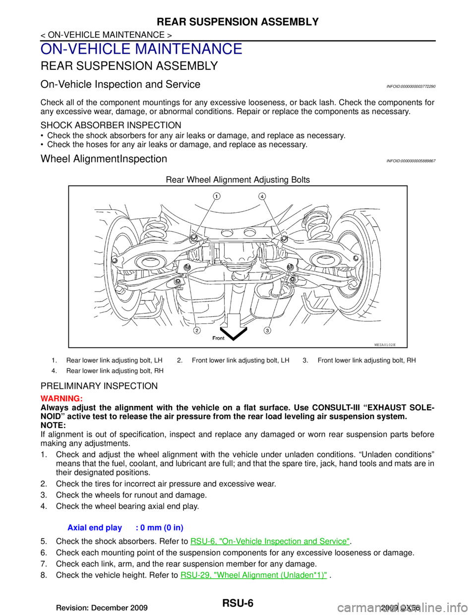
Wheel AlignmentInspectionINFOID:0000000005889867
Rear Wheel Alignment Adjusting Bolts
PRELIMINARY INSPECTION
WARNING:
Always adjust the alignm ent with the vehicle on a flat su rface. Use CONSULT-III “EXHAUST SOLE-
NOID” active test to release the air pressure from the rear load leveling air suspension system.
NOTE:
If alignment is out of specificat ion, inspect and replace any damaged or worn rear suspension parts before
making any adjustments.
1. Check and adjust the wheel alignment with the vehicle under unladen conditions. “Unladen conditions”
means that the fuel, coolant, and lubricant are full; and that the spare tire, jack, hand tools and mats are in
their designated positions.
2. Check the tires for incorrect air pressure and excessive wear.
3. Check the wheels for runout and damage.
4. Check the wheel bearing axial end play.
5. Check the shock absorbers. Refer to RSU-6, "On-Vehicle Inspection and Service"
.
6. Check each mounting point of the suspension components for any excessive looseness or damage.
7. Check each link, arm, and the rear suspension member for any damage.
8. Check the vehicle height. Refer to RSU-29, "Wheel Alignment (Unladen
*1)" .
WEIA0102E
1. Rear lower link adjusting bolt, LH 2. Front lower link adjusting bolt, LH 3. Front lower link adjusting bolt, RH
4. Rear lower link adjusting bolt, RH
Axial end play : 0 mm (0 in)
Revision: December 20092009 QX56
Page 3157 of 4171
REAR SUSPENSION ASSEMBLYRSU-9
< ON-VEHICLE REPAIR >
C
DF
G H
I
J
K L
M A
B
RSU
N
O P
ON-VEHICLE REPAIR
REAR SUSPENSION ASSEMBLY
ComponentINFOID:0000000005889868
Rear Suspension Without Rear Lo ad Leveling Air Suspension System
AWEIA0164GB
Revision: December 20092009 QX56
Page 3158 of 4171
RSU-10
< ON-VEHICLE REPAIR >
REAR SUSPENSION ASSEMBLY
Rear Load Leveling Air Suspension System
1. Seat belt latch anchor 2. Stabilizer bar bushing 3. Stabilizer bar clamp
4. Stabilizer bar 5. Connecting rod 6. Front lower link
7. Knuckle 8. Bushing 9. Rear lower link
10. Shock absorber 11. Suspension arm 12. Lower rubber seat
13. Coil spring 14. Upper rubber seat 15. Rear suspension member
16. Spare tire bracket 17. Bound bumper Front
AWEIA0054GB
1. Rear load leveling air suspension hose, RH 2. Shock absorber, RH 3. Height sensor
4. Rear load leveling air suspension hose, LH 5. Shock absorber, LH 6. Rear load leveling air suspension
compressor assembly
Front
Revision: December 20092009 QX56
Page 3159 of 4171
REAR SUSPENSION MEMBERRSU-11
< REMOVAL AND INSTALLATION >
C
DF
G H
I
J
K L
M A
B
RSU
N
O P
REMOVAL AND INSTALLATION
REAR SUSPENSION MEMBER
Removal and InstallationINFOID:0000000005889869
Rear Suspension Without Rear Lo ad Leveling Air Suspension System
AWEIA0164GB
Revision: December 20092009 QX56