2009 INFINITI QX56 air suspension
[x] Cancel search: air suspensionPage 3603 of 4171

ST-12
< SYMPTOM DIAGNOSIS >
NOISE, VIBRATION AND HARSHNESS (NVH) TROUBLESHOOTING
SYMPTOM DIAGNOSIS
NOISE, VIBRATION AND HARSHNESS (NVH) TROUBLESHOOTING
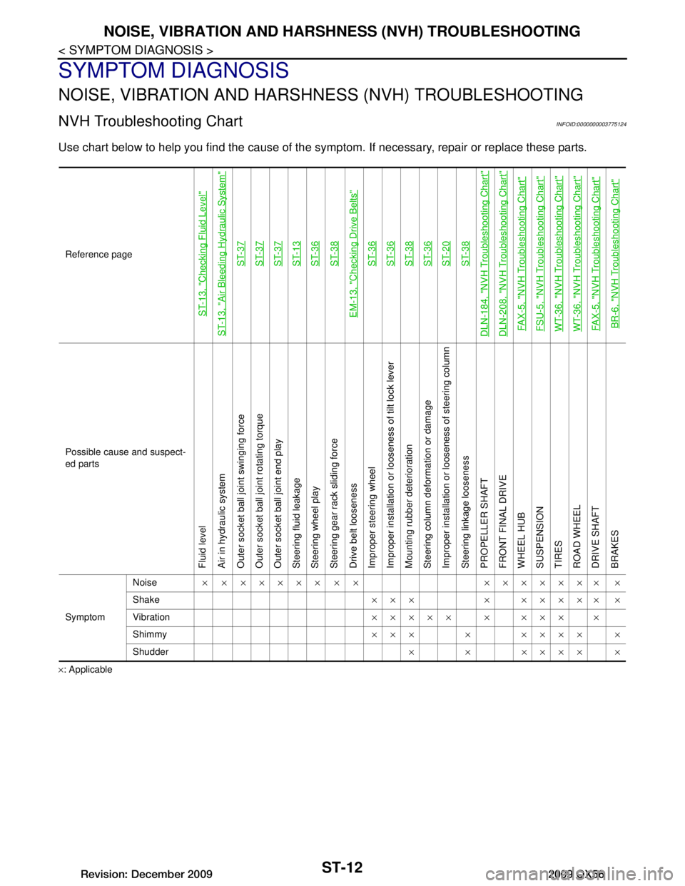
NVH Troubleshooting ChartINFOID:0000000003775124
Use chart below to help you find the cause of the symp tom. If necessary, repair or replace these parts.
×: ApplicableReference page
ST-13, "Checking Fluid Level"
ST-13, "Air Bleeding Hydraulic System"
ST-37ST-37ST-37ST-13ST-36ST-38
EM-13, "Checking Drive Belts"
ST-36ST-36ST-38ST-36ST-20ST-38
DLN-184, "NVH Troubleshooting Chart"DLN-208, "NVH Troubleshooting Chart"FAX-5, "NVH Troubleshooting Chart"FSU-5, "NVH Troubleshooting Chart"WT-36, "NVH Troubleshooting Chart"WT-36, "NVH Troubleshooting Chart"FAX-5, "NVH Troubleshooting Chart"BR-6, "NVH Troubleshooting Chart"
Possible cause and suspect-
ed parts
Fluid level
Air in hydraulic system
Outer socket ball joint swinging force
Outer socket ball joint rotating torque
Outer socket ball joint end play
Steering fluid leakage
Steering wheel play
Steering gear rack sliding force
Drive belt looseness
Improper steering wheel
Improper installation or looseness of tilt lock lever
Mounting rubber deterioration
Steering column deformation or damage
Improper installation or looseness of steering column
Steering linkage looseness
PROPELLER SHAFT
FRONT FINAL DRIVE
WHEEL HUB
SUSPENSION
TIRES
ROAD WHEEL
DRIVE SHAFT
BRAKES
Symptom
Noise
× × ××××× × × ××××××× ×
Shake ××× × ××××× ×
Vibration ××××× × ××× ×
Shimmy ××× × ×××× ×
Shudder × × ×××× ×
Revision: December 20092009 QX56
Page 3606 of 4171

STEERING WHEELST-15
< ON-VEHICLE REPAIR >
C
DE
F
H I
J
K L
M A
B
ST
N
O P
ON-VEHICLE REPAIR
STEERING WHEEL
On-Vehicle Inspection and ServiceINFOID:0000000004187602
CHECKING CONDITION OF INSTALLATION
Check installation condition of steering gear assemb ly, front suspension, axle and steering column.
Check if movement exists when steering wheel is mo ved up and down, to the left and right and to the axial
direction.
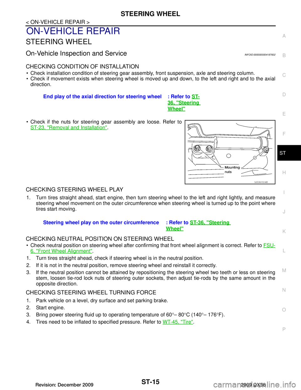
Check if the nuts for steering gear assembly are loose. Refer to ST-23, "Removal and Installation"
.
CHECKING STEERING WHEEL PLAY
1. Turn tires straight ahead, start engine, then turn steer ing wheel to the left and right lightly, and measure
steering wheel movement on the outer circumference when steering wheel is turned up to the point where
tires start moving.
CHECKING NEUTRAL POSITION ON STEERING WHEEL
Check neutral position on steering wheel after confirming that front wheel alignment is correct. Refer to FSU-
6, "Front Wheel Alignment".
1. Turn tires straight ahead, check if st eering wheel is in the neutral position.
2. If it is not in the neutral position, remo ve steering wheel and reinstall it correctly.
3. If the neutral position cannot be attained by repositi oning the steering wheel two teeth or less on steering
stem, loosen tie-rod lock nuts of steering outer socket s, then adjust tie-rods by the same amount in the
opposite direction.
CHECKING STEERING WHEEL TURNING FORCE
1. Park vehicle on a level, dry surface and set parking brake.
2. Start engine.
3. Bring power steering fluid up to operating temperature of 60 °– 80 °C (140 °– 176 °F).
4. Tires need to be inflated to specified pressure. Refer to WT-45, "Tire"
.
End play of the axial direction for steering wheel : Refer to
ST-
36, "Steering
Wheel"
LGIA0024E
Steering wheel play on the outer circumference : Refer to ST-36, "Steering
Wheel"
Revision: December 20092009 QX56
Page 4043 of 4171

WT-1
SUSPENSION
C
DF
G H
I
J
K L
M
SECTION WT
A
B
WT
N
O PCONTENTS
ROAD WHEELS & TIRES
BASIC INSPECTION ....... .............................3
DIAGNOSIS AND REPAIR WORKFLOW ..... .....3
Repair Work Flow ................................................ ......3
INSPECTION AND ADJUSTMENT .....................5
Preliminary Check ............................................... ......5
Transmitter Wake Up Operation ...............................5
ID Registration Procedure .........................................6
FUNCTION DIAGNOSIS ...............................8
TPMS .............................................................. .....8
System Diagram .................................................. ......8
System Description ...................................................8
System Component .................................................10
DIAGNOSIS SYSTEM (BCM) ............................11
CONSULT-III Function (BCM) ............................. ....11
Self-Diagnosis (With CONSULT-III) ........................12
Self-Diagnosis (Without CONSULT-III) ...................13
COMPONENT DIAGNOSIS .........................14
C1708 - C1711 DATA FROM TRANSMITTER
NOT BEING RECEIVED ................................. ....
14
Description .......................................................... ....14
DTC Logic ...............................................................14
Data from Transmitter Not Being Received ............14
Special Repair Requirement ...................................15
C1712 - C1715, C1720 - C1723, C1724 -
C1727 TRANSMITTER MALFUNCTION ....... ....
16
Description .......................................................... ....16
DTC Logic ...............................................................16
Transmitter Malfunction ...........................................16
Special Repair Requirement ...................................17
C1716 - C1719 TRANSMITTER PRESSURE
MALFUNCTION .............................................. ....
18
Description .......................................................... ....18
DTC Logic ...............................................................18
Transmitter Pressure Malfunction ............................18
Special Repair Requirement ................................ ....18
C1729 VEHICLE SPEED SIGNAL ....................19
Description ...............................................................19
DTC Logic ................................................................19
Vehicle Speed Signal ..............................................19
C1735 IGNITION SIGNAL .................................20
Description ...............................................................20
DTC Logic ................................................................20
Diagnosis Procedure ...............................................20
ECU DIAGNOSIS .........................................21
BCM (BODY CONTROL MODULE) .................21
Reference Value .................................................. ....21
Wiring Diagram ........................................................23
Self-Diagnosis (With CONSULT-III) ........................26
Self-Diagnosis (Without CONSULT-III) ...................27
SYMPTOM DIAGNOSIS ..............................29
TPMS .................................................................29
Symptom Table ................................................... ....29
LOW TIRE PRESSURE WARNING LAMP
DOES NOT TURN ON .......................................
30
Low Tire Pressure Warning Lamp Does Not Come
On When Ignition Switch Is Turned On ...................
30
LOW TIRE PRESSURE WARNING LAMP
STAYS ON ........................................................
31
Low Tire Pressure Warning Lamp Stays On When
Ignition Switch Is Turned On ............................... ....
31
LOW TIRE PRESSURE WARNING LAMP
BLINKS .............................................................
32
Low Tire Pressure Warning Lamp Flashes When
Ignition Switch Is Turned On ...................................
32
HAZARD WARNING LAMPS FLASH ..............33
Revision: December 20092009 QX56
Page 4078 of 4171

WT-36
< SYMPTOM DIAGNOSIS >
NOISE, VIBRATION AND HARSHNESS (NVH) TROUBLESHOOTING
NOISE, VIBRATION AND HARSHNESS (NVH) TROUBLESHOOTING
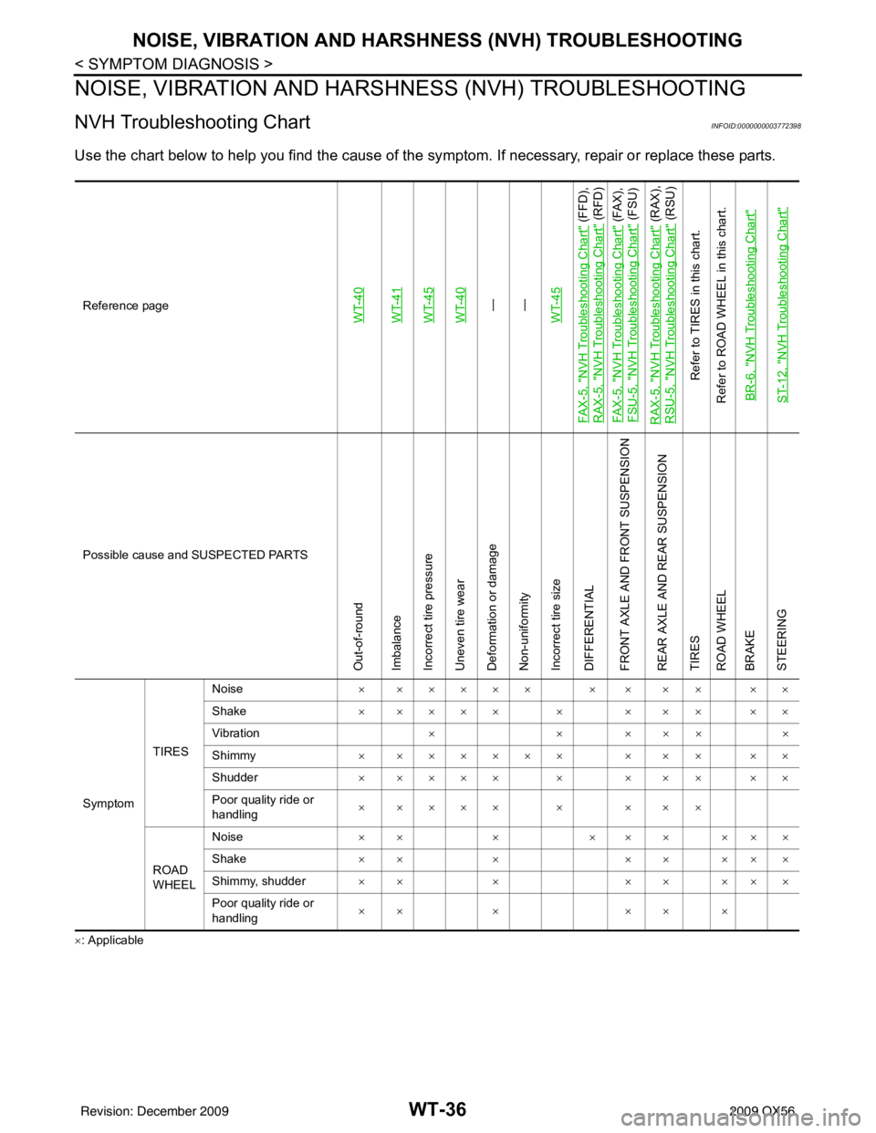
NVH Troubleshooting ChartINFOID:0000000003772398
Use the chart below to help you find the cause of the sy mptom. If necessary, repair or replace these parts.
×: ApplicableReference page
WT-40WT-41WT-45WT-40—
—
WT-45
FA X - 5 , "
NVH Troubleshooting Chart
" (FFD),
RAX-5, "
NVH Troubleshooting Chart
" (RFD)
FA X - 5 , "
NVH Troubleshooting Chart
" (FAX),
FSU-5, "
NVH Troubleshooting Chart
" (FSU)
RAX-5, "
NVH Troubleshooting Chart
" (RAX),
RSU-5, "
NVH Troubleshooting Chart
" (RSU)
Refer to TIRES in this chart.
Refer to ROAD WHEEL in this chart.
BR-6, "
NVH Troubleshooting Chart
"
ST-12, "
NVH Troubleshooting Chart
"
Possible cause and SUSPECTED PARTS
Out-of-round
Imbalance
Incorrect tire pressure
Uneven tire wear
Deformation or damage
Non-uniformity
Incorrect tire size
DIFFERENTIAL
FRONT AXLE AND FRONT SUSPENSION
REAR AXLE AND REAR SUSPENSION
TIRES
ROAD WHEEL
BRAKE
STEERING
Symptom TIRESNoise
× ××××× × × × × ××
Shake × ×××× × × × × ××
Vibration ××× ×××
Shimmy × ×××××× × × × ××
Shudder × ×××× × × × × ××
Poor quality ride or
handling × ×××× × × × ×
ROAD
WHEEL Noise
×× × ××× ×××
Shake ×× × ×× ×××
Shimmy, shudder ×× × ×× ×××
Poor quality ride or
handling ×× ×
×× ×
Revision: December 20092009 QX56