2009 INFINITI QX56 service
[x] Cancel search: servicePage 2179 of 4171

ON-VEHICLE SERVICEFSU-9
< ON-VEHICLE MAINTENANCE >
C
DF
G H
I
J
K L
M A
B
FSU
N
O P
• Any turning angles are not adjustable. If any of steering angles are out of the specification, check if the following parts are worn or damaged.
- Steering gear
- Steering column
- Front suspension components If found that they are worn or damaged, replace them with new ones.
Revision: December 20092009 QX56
Page 2182 of 4171

FSU-12
< ON-VEHICLE MAINTENANCE >
KNUCKLE
KNUCKLE
On-Vehicle Inspection and ServiceINFOID:0000000003772272
Make sure the mounting conditions (looseness, backlash) of each component and component status (wear,
damage) are within specifications. Refer to FSU-24, "
Ball Joint" .
Revision: December 20092009 QX56
Page 2193 of 4171

SERVICE DATA AND SPECIFICATIONS (SDS)FSU-23
< SERVICE DATA AND SPECIFICATIONS (SDS)
C
DF
G H
I
J
K L
M A
B
FSU
N
O P
SERVICE DATA AND SPECIFICATIONS (SDS)
SERVICE DATA AND SPECIFICATIONS (SDS)
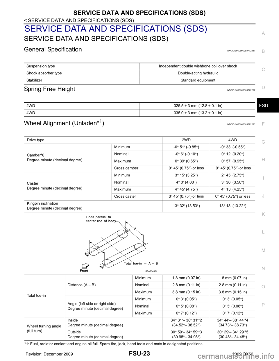
General SpecificationINFOID:0000000003772281
Spring Free HeightINFOID:0000000003772282
Wheel Alignment (Unladen*1)INFOID:0000000003772283
*1: Fuel, radiator coolant and engine oil full. Spare tire, jack, hand tools and mats in designated positions. Suspension type
Independent double wishbone coil over shock
Shock absorber type Double-acting hydraulic
Stabilizer Standard equipment
2WD325.5 ± 3 mm (12.8 ± 0.1 in)
4WD 335.0 ± 3 mm (13.2 ± 0.1 in)
Drive type 2WD 4WD
Camber*6
Degree minute (decimal degree) Minimum
-0° 51 ′ (-0.85 °)- 0° 33 ′ (-0.55 °)
Nominal -0° 6 ′ (-0.10 °)0 ° 12 ′ (0.20 °)
Maximum 0° 39 ′ (0.65 °)0 ° 57 ′ (0.95 °)
Cross camber 0° 45 ′ (0.75 °) or less 0 ° 45′ (0.75 °) or less
Caster
Degree minute (decimal degree) Minimum
3° 15 ′ (3.25 °)2 ° 45 ′ (2.75 °)
Nominal 4° 0 ′ (4.00 °)3 ° 30 ′ (3.50 °)
Maximum 4° 45 ′ (4.75 °)4 ° 15 ′ (4.25 °)
Cross caster 0° 45 ′ (0.75 °) or less 0
° 45 ′ (0
.75°) or less
Kingpin inclination
Degree minute (decimal degree) 13
° 32 ′ (13.53 °)1 3° 13 ′ (13.22 °)
Total toe-in Distance (A
− B) Minimum
1.8 mm (0.07 in) 1.8 mm (0.07 in)
Nominal 2.8 mm (0.11 in) 2.8 mm (0.11 in)
Maximum 3.8 mm (0.15 in) 3.8 mm (0.15 in)
Angle (left side or right side)
Degree minute (decimal degree) Minimum
0° 3 ′ (0.05 °)0 ° 3 ′ (0.05 °)
Nominal 0° 5 ′ (0.08 °)0 ° 5 ′ (0.08 °)
Maximum 0° 7 ′ (0.12 °)0 ° 7 ′ (0.12 °)
Wheel turning angle
(full turn) Inside
Degree minute (decimal degree)
34
° 31 ′– 38 ° 31 ′*2
(34.52 °– 38.52° ) 34
° 44 ′– 38° 44′*4
(34.73 °– 38.73 °)
Ou t
side
Degree minute (decimal degree) 30
° 59 ′– 34 ° 59 ′*3
(30.98 °– 34.98° ) 30
° 29 ′– 34° 29′*5
(30.48 °– 34.48 °)
SFA234AC
Revision: December 20092009 QX56
Page 2194 of 4171

FSU-24
< SERVICE DATA AND SPECIFICATIONS (SDS)
SERVICE DATA AND SPECIFICATIONS (SDS)
*2: Target value 37° 31 ′ (37.52 °)
*3: Target value 33 ° 59 ′ (33.98 °)
*4: Target value 37 ° 44 ′ (37.73 °)
*5: Target value 33 ° 29 ′ (33.48 °)
*6 Some vehicles may not be equipped with straight (non-adjustable) lower link bolts and washers. In order to adjust camber and caster
on these vehicles, first replace the lower link bolts and washers with adjustable (cam) bolts and washers
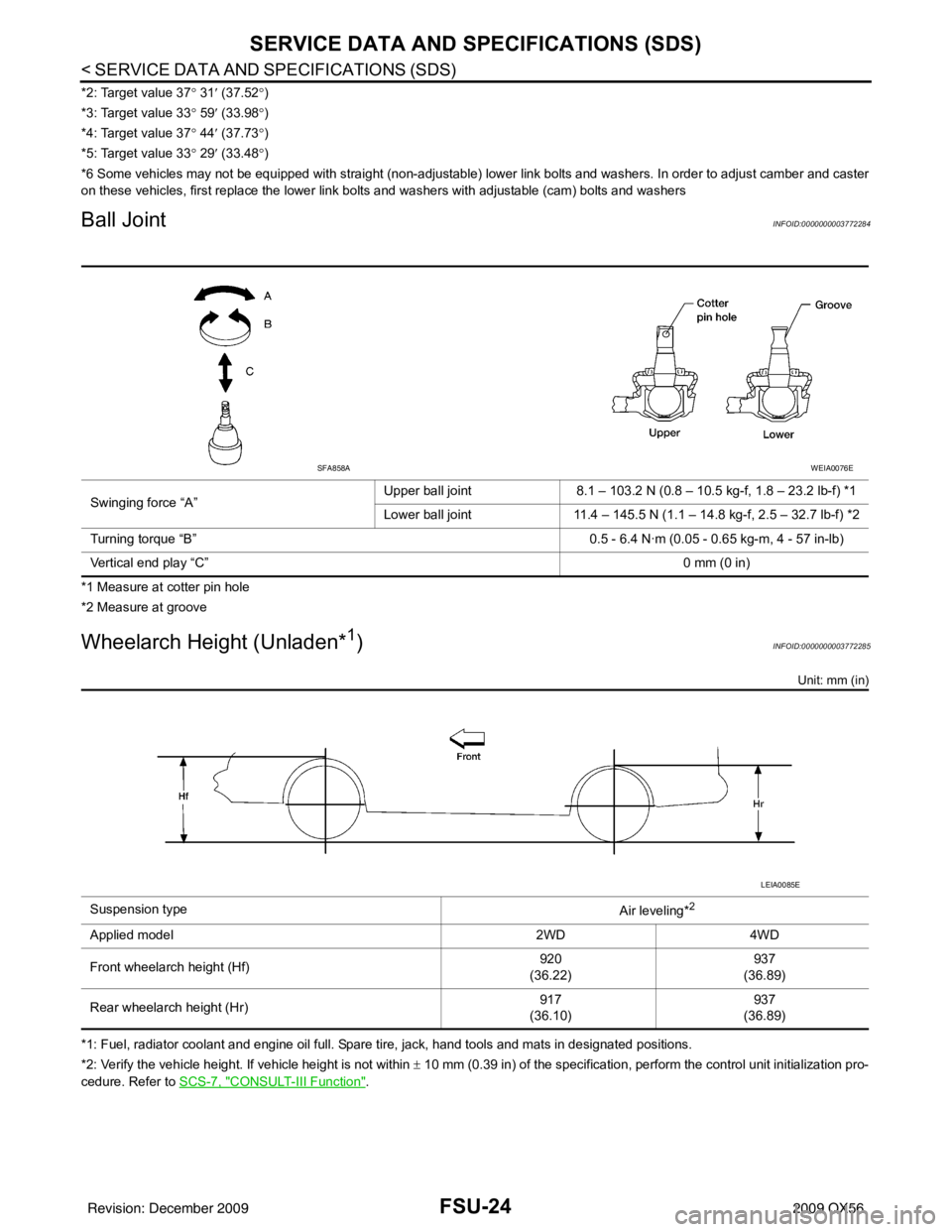
Ball JointINFOID:0000000003772284
*1 Measure at cotter pin hole
*2 Measure at groove
Wheelarch Height (Unladen*1)INFOID:0000000003772285
Unit: mm (in)
*1: Fuel, radiator coolant and engine oil full. Spare tire, jack, hand tools and mats in designated positions.
*2: Verify the vehicle height. If vehicle height is not within ± 10 mm (0.39 in) of the specification, perform the control unit initialization pro-
cedure. Refer to SCS-7, "
CONSULT-III Function".
Swinging force “A”
Upper ball joint
8.1 – 103.2 N (0.8 – 10.5 kg-f, 1.8 – 23.2 lb-f) *1
Lower ball joint 11.4 – 145.5 N (1.1 – 14.8 kg-f, 2.5 – 32.7 lb-f) *2
Turning torque “B” 0.5 - 6.4 N·m (0.05 - 0.65 kg-m, 4 - 57 in-lb)
Vertical end play “C” 0 mm (0 in)
SFA858AWEIA0076E
Suspension type
Air leveling*2
Applied model2WD4WD
Front wheelarch height (Hf) 920
(36.22) 937
(36.89)
Rear wheelarch height (Hr) 917
(36.10) 937
(36.89)
LEIA0085E
Revision: December 20092009 QX56
Page 2195 of 4171

GI-1
GENERAL INFORMATION
C
DE
F
G H
I
J
K L
M B
GI
SECTION GI
N
O P
CONTENTS
GENERAL INFORMATION
HOW TO USE THIS MANU AL ......................3
HOW TO USE THIS MANUAL ....................... .....3
Description .......................................................... ......3
Terms ........................................................................3
Units ..........................................................................3
Contents ....................................................................3
Relation between Illustrations and Descriptions .......4
Components ..............................................................4
HOW TO FOLLOW TROUBLE DIAGNOSES .....6
Description ................................................................6
How to Follow Test Groups in Trouble Diagnosis ......6
Key to Symbols Signifying Measurements or Pro-
cedures ............................................................... ......
7
HOW TO READ WIRING DIAGRAMS ................9
Connector symbols ............................................. ......9
Sample/wiring diagram -example- ...........................10
Description ..............................................................11
ABBREVIATIONS .......................................... ....13
Abbreviation List .................................................. ....13
TIGHTENING TORQUE OF STANDARD
BOLTS ................................................................
14
Tightening Torque Table .........................................14
RECOMMENDED CHEMICAL PRODUCTS
AND SEALANTS ............................................ ....
15
Recommended Chemical Products and Sealants ....15
TERMINOLOGY .................................................16
SAE J1930 Terminology List ............................... ....16
FEATURES OF NEW MODEL .....................20
IDENTIFICATION INFORMATION .....................20
Model Variation ................................................... ....20
Identification Number ..............................................21
Identification Plate ...................................................22
Dimensions .............................................................23
Wheels & Tires .................................................... ....23
PRECAUTION ..............................................24
PRECAUTIONS .................................................24
Description ........................................................... ....24
Precaution for Supplemental Restraint System
(SRS) "AIR BAG" and "SEAT BELT PRE-TEN-
SIONER" .................................................................
24
Precaution Necessary for Steering Wheel Rota-
tion After Battery Disconnect ...................................
24
Procedures without Cowl Top Cover .......................25
General Precautions ................................................25
Three Way Catalyst .................................................27
Precaution for Fuel (Unleaded Premium Gasoline
Recommended) .......................................................
27
Multiport Fuel Injection System or Engine Control
System .....................................................................
27
Hoses ......................................................................27
Engine Oils ..............................................................28
Air Conditioning .......................................................29
LIFTING POINT .................................................30
Pantograph Jack ......................................................30
Garage Jack and Safety Stand ................................30
2-Pole Lift ................................................................30
TOW TRUCK TOWING .....................................32
Tow Truck Towing ...................................................32
Vehicle Recovery (Freeing a stuck vehicle) ............33
BASIC INSPECTION ...................................34
SERVICE INFORMATION FOR ELECTRICAL
INCIDENT ..........................................................
34
Work Flow ............................................................ ....34
Control Units and Electrical Parts ............................34
How to Check Terminal ...........................................35
Intermittent Incident ............................................. ....38
Circuit Inspection .....................................................41
CONSULT-III CHECKING SYSTEM .................46
Revision: December 20092009 QX56
Page 2198 of 4171

GI-4
< HOW TO USE THIS MANUAL >
HOW TO USE THIS MANUAL
Relation between Illustrations and Descriptions
INFOID:0000000003771177
The following sample explains the relationship between t he part description in an illustration, the part name in
the text and the service procedures.
ComponentsINFOID:0000000003771178
• THE LARGE ILLUSTRATIONS are exploded views (see the following) and contain tightening torques, lubri-
cation points, section number of the PARTS CATALOG (e.g. SEC. 440) and other information necessary to
perform repairs.
The illustrations should be used in reference to service matters only. When ordering parts, refer to the appro-
priate PARTS CATALOG .
Always check with the PARTS DEPARTMENT for the latest parts information.
Components shown in an illustration may be identified by a circled number. When this style of illustration is
used, the text description of the components will follow the illustration.
SAIA0519E
Revision: December 20092009 QX56
Page 2207 of 4171

ABBREVIATIONSGI-13
< HOW TO USE THIS MANUAL >
C
DE
F
G H
I
J
K L
M B
GI
N
O PABBREVIATIONS
Abbreviation ListINFOID:0000000003771185
The following ABBREVIATIONS are used:
ABBREVIATION DESCRIPTION
A/C Air Conditioner
A/T Automatic Transaxle/Transmission
ATF Automatic Transmission Fluid
D
1Drive range 1[First Gear (1 GR)]
D
2Drive range 2 [Second Gear (2 GR)]
D
3Drive range 3 [Third Gear (3 GR)]
D
4Drive range 4 [Fourth Gear (4 GR)]
FR, RR Front, Rear LH, RH Left-Hand, Right-Hand M/T Manual Transaxle/Transmission
OD Overdrive
P/S Power Steering
SAE Society of Automotive Engineers, Inc.
SDS Service Data and Specifications
SST Special Service Tools
2WD 2-Wheel Drive
4WD 4-Wheel Drive
2
22nd range [Second Gear (2 GR)]
2
12nd range [First Gear (1 GR)]
1
21st range [Second Gear (2 GR)]
1
11st range [First Gear (1 GR)]
Revision: December 20092009 QX56
Page 2209 of 4171

RECOMMENDED CHEMICAL PRODUCTS AND SEALANTS
GI-15
< HOW TO USE THIS MANUAL >
C
D E
F
G H
I
J
K L
M B
GI
N
O PRECOMMENDED CHEMICAL PRODUCTS AND SEALANTS
Recommended Chemical Products and SealantsINFOID:0000000003771187
Refer to the following chart for help in selecting the appropriate chemical product or sealant.
Product Description PurposeNissan North America
Part No. (USA) Nissan Canada Part
No. (Canada) Aftermarket Cross-
reference Part Nos.
1 Rear View Mirror Adhe-
sive Used to permanently re-
mount rear view mirrors to
windows.
999MP-AM000P 99998-50505
Permatex 81844
2 Anaerobic Liquid Gas-
ket For metal-to-metal flange
sealing.
Can fill a 0.38 mm (0.015
inch) gap and provide in-
stant sealing for most pow-
ertrain applications.
999MP-AM001P 99998-50503
Permatex 51813 and
51817
3 High Performance
Thread Sealant Provides instant sealing on
any threaded straight or
parallel threaded fitting.
(Thread sealant only, no
locking ability.)
• Do not use on plastic.
999MP-AM002P 999MP-AM002P Permatex 56521
4 Silicone RTV Gasket Maker
999MP-AM003P
(Ultra Grey)99998-50506
(Ultra Grey)Permatex Ultra Grey
82194;
Three Bond
1207,1215, 1216,
1217F, 1217G and
1217H
Nissan RTV Part No.
999MP-A7007
Gasket Maker for Maxima/
Quest 5-speed automatic
transmission
(RE5F22A) ––
Three Bond 1281B
or exact equivalent in
its quality
5 High Temperature,
High Strength Thread
Locking Sealant (Red)
Threadlocker
999MP-AM004P 999MP-AM004P Permatex 27200;
Three Bond 1360,
1360N, 1305 N&P,
1307N, 1335,
1335B, 1363B,
1377C, 1386B, D&E
and 1388
Loctite 648
6 Medium Strength
Thread Locking Seal-
ant (Blue) Threadlocker (service tool
removable)
999MP-AM005P 999MP-AM005P Permatex 24200,
24206, 24240,
24283 and 09178;
Three Bond 1322,
1322N, 1324 D&N,
1333D, 1361C,
1364D, 1370C and
1374
Revision: December 20092009 QX56