Page 2307 of 4171

HIGH-PRESSURE PIPEHA-43
< ON-VEHICLE REPAIR >
C
DE
F
G H
J
K L
M A
B
HA
N
O P
5. Remove the front and rear bumper fascia. Refer to EXT-13, "Removal and Installation" (front), EXT-15,
"Removal and Installation" (rear).
6. Reposition the front fender protec tor out of the way. Refer to EXT-23, "Removal and Installation"
.
7. Disconnect the chassis harness connector.
8. Remove the spare wheel and tire.
9. Remove the tailpipe and tailpipe hanger bracket. Refer to EX-6, "Removal and Installation"
.
10. Remove the seatbelt latch anchor. Refer to EX-6, "Removal and Installation"
.
11. Remove the front floor heat shield.
12. Disconnect each end of the underfloor rear high- and low-pressure A/C and heater core pipes. Refer to
HA-29, "Component"
.
CAUTION:
Cap or wrap the joint of the pipes with suitable material such as viny l tape to avoid the entry of air.
13. Set two suitable jacks at the RH body mount points to support the vehicle body when it is separated from the RH side of the frame.
14. Remove the RH body mount bolts. Refer to BRM-6, "Body Mounting"
.
15. Use the vehicle hoist to lower the RH side of the frame from the RH side of the body [approximately 305
mm (12 in)] until there is suffici ent clearance to remove the underfloor rear high- and low-pressure A/C
and heater core pipes from between the body and the frame.
16. Remove the underfloor rear high- and low-pressure A/ C and heater core pipes from the back of the vehi-
cle.
INSTALLATION
Installation is in the reverse order of removal.
CAUTION:
Replace the O-rings of the underfloor rear high - and low-pressure A/C and heater core pipes with
new ones, then apply compressor oil to them for installation.
After charging refrigerant, check for leaks.
Revision: December 20092009 QX56
Page 2308 of 4171

HA-44
< ON-VEHICLE REPAIR >
CONDENSER
CONDENSER
Removal and Installation for CondenserINFOID:0000000003775319
REMOVAL
1. Discharge the refrigerant. Refer to HA-20, "HFC-134a (R-134a) Service Procedure".
2. Remove the radiator. Refer to CO-15, "Removal and Installation"
.
CAUTION:
Be careful not to damage the core su rface of the condenser and the radiator.
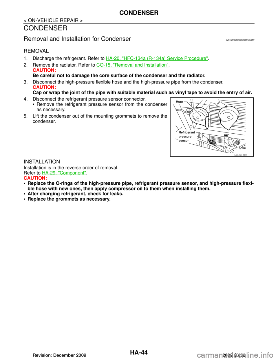
3. Disconnect the high-pressure flexible hose and the high-pressure pipe from the condenser.
CAUTION:
Cap or wrap the joint of the pipe with suitable ma terial such as vinyl tape to avoid the entry of air.
4. Disconnect the refrigerant pressure sensor connector. Remove the refrigerant pressure sensor from the condenseras necessary.
5. Lift the condenser out of the mounting grommets to remove the condenser.
INSTALLATION
Installation is in the reverse order of removal.
Refer to HA-29, "Component"
.
CAUTION:
Replace the O-rings of the high-p ressure pipe, refrigerant pressure sensor, and high-pressure flexi-
ble hose with new ones, then apply compr essor oil to them when installing them.
After charging refrigerant, check for leaks.
Replace the grommets as necessary.
LJIA0145E
Revision: December 20092009 QX56
Page 2310 of 4171
HA-46
< ON-VEHICLE REPAIR >
REFRIGERANT PRESSURE SENSOR
REFRIGERANT PRESSURE SENSOR
Removal and Installation for Refrigerant Pressure SensorINFOID:0000000003775321
REMOVAL
1. Discharge the refrigerant. Refer to HA-20, "HFC-134a (R-134a) Service Procedure".
2. Disconnect the refrigerant pressu re sensor electrical connector
and remove the refrigerant pressure sensor from the condenser.
CAUTION:
Be careful not to damage the condenser fins.
INSTALLATION
Installation is in the reverse order of removal.
Refer to HA-29, "Component"
.
CAUTION:
Be careful not to damage the condenser fins.
Replace the O-ring of the refriger ant pressure sensor with a new one, then apply compressor oil to it
when installing it.
After charging refrigerant, check for leaks.
LJIA0145E
Revision: December 20092009 QX56
Page 2311 of 4171
EXPANSION VALVEHA-47
< ON-VEHICLE REPAIR >
C
DE
F
G H
J
K L
M A
B
HA
N
O P
EXPANSION VALVE
Removal and Installation for Front Expansion ValveINFOID:0000000003775322
REMOVAL
1. Discharge the refrigerant. Refer to HA-20, "HFC-134a (R-134a) Service Procedure".
2. Remove the front evaporator. Refer to VTL-35, "Removal and Installation for Front Evaporator"
.
3. Remove the cooler grommet.
4. Remove the expansion valve.
INSTALLATION
Installation is in the reverse order of removal.
CAUTION:
Replace the O-rings on the A/C re frigerant pipes with new ones, then apply compressor oil to them
when installing them.
After charging refrigerant, check for leaks.
WJIA0582E
Expansion valve bolts : 4 N·m (0.41 kg-m, 35 in-lb)
A/C refrigerant pipe to expansion valve bolt : Refer to HA-29, "Component"
.
Revision: December 20092009 QX56
Page 2312 of 4171

HA-48
< ON-VEHICLE REPAIR >
LIQUID TANK
LIQUID TANK
Removal and Installation of Liquid TankINFOID:0000000005873219
REMOVAL
1. Remove the condenser. Refer to HA-44, "Removal and Installation for Condenser" .
2. Clean liquid tank and its surrounding area, and remove dirt and rust from liquid tank. CAUTION:
Be sure to clean carefully.
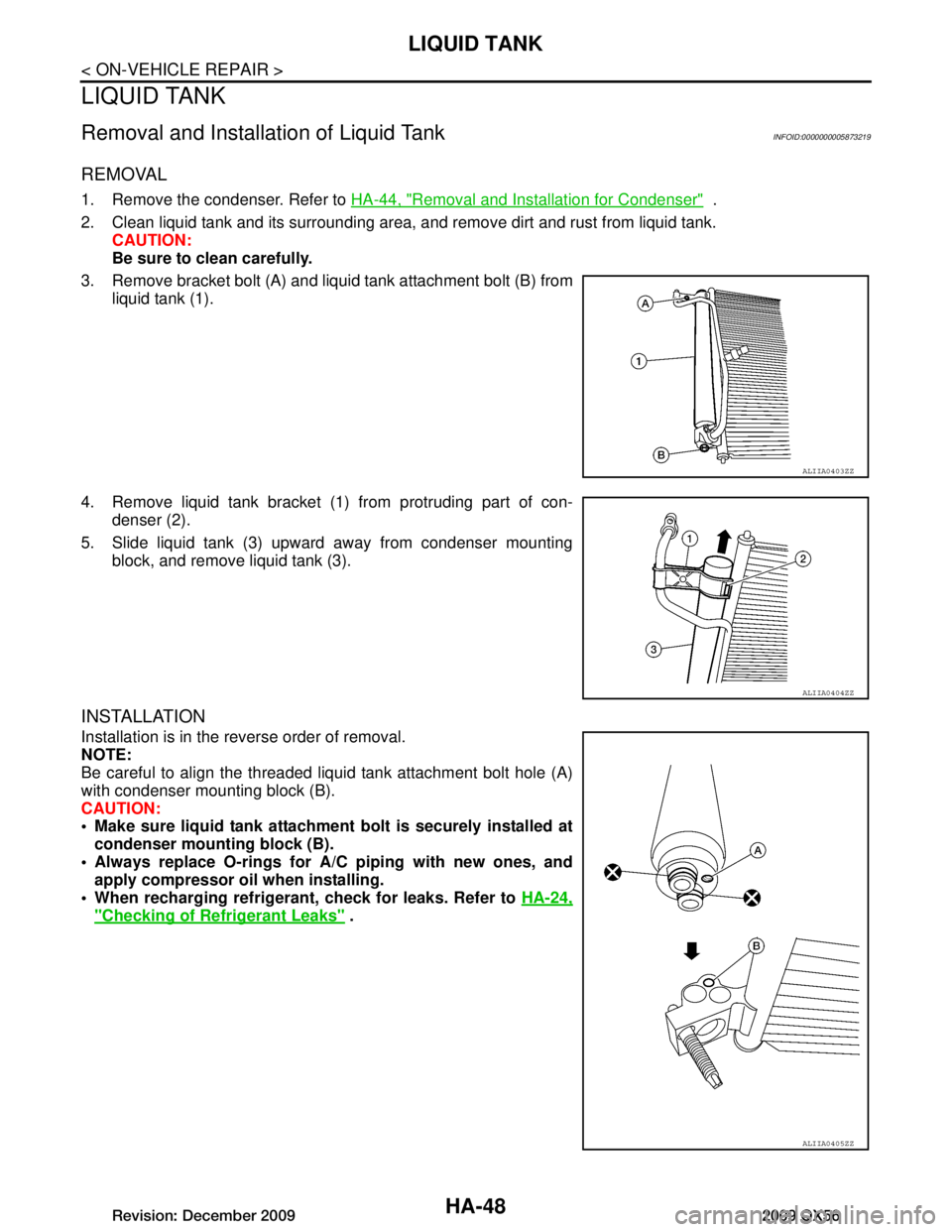
3. Remove bracket bolt (A) and liquid tank attachment bolt (B) from liquid tank (1).
4. Remove liquid tank bracket (1) from protruding part of con- denser (2).
5. Slide liquid tank (3) upward away from condenser mounting block, and remove liquid tank (3).
INSTALLATION
Installation is in the reverse order of removal.
NOTE:
Be careful to align the threaded liquid tank attachment bolt hole (A)
with condenser mounting block (B).
CAUTION:
Make sure liquid tank attachment bolt is securely installed atcondenser mounti ng block (B).
Always replace O-rings for A/C piping with new ones, and
apply compressor oil when installing.
When recharging refrigeran t, check for leaks. Refer to HA-24,
"Checking of Refrigerant Leaks" .
ALIIA0403ZZ
ALIIA0404ZZ
ALIIA0405ZZ
Revision: December 20092009 QX56
Page 2313 of 4171
SERVICE DATA AND SPECIFICATIONS (SDS)
HA-49
< SERVICE DATA AND SPECIFICATIONS (SDS)
C
D E
F
G H
J
K L
M A
B
HA
N
O P
SERVICE DATA AND SPECIFICATIONS (SDS)
SERVICE DATA AND SPECIFICATIONS (SDS)
Service Data and Specification (SDS)INFOID:0000000003775323
COMPRESSOR
OIL
REFRIGERANT
Make ZEXEL VALEO CLIMATE CONTROL
Model DKS-17D
Typ e Swash plate
Displacement 175.5 cm
3 (10.7 in3 ) / revolution
Cylinder bore × stroke 30.5 mm (1.20 in) x 24.0 mm (0.94 in)
Direction of rotation Clockwise (viewed from drive end)
Drive belt Poly V
Name NISSAN A/C System Oil Type S
Capacity 290 m (9.8 US fl oz, 10.2 Imp fl oz)
Typ eHFC 134a (R-134a)
Capacity 1.08 ± 0.05 kg (2.38 ± 0.11 lb)
Revision: December 20092009 QX56
Page 2324 of 4171
![INFINITI QX56 2009 Factory Service Manual REFRIGERATION SYSTEMHAC-11
< FUNCTION DIAGNOSIS > [AUTOMATIC AIR CONDITIONER]
C
D
E
F
G H
J
K L
M A
B
HAC
N
O P
REFRIGERATION SYSTEM
Refrigerant CycleINFOID:0000000004040375
REFRIGERANT FLOW
The refri INFINITI QX56 2009 Factory Service Manual REFRIGERATION SYSTEMHAC-11
< FUNCTION DIAGNOSIS > [AUTOMATIC AIR CONDITIONER]
C
D
E
F
G H
J
K L
M A
B
HAC
N
O P
REFRIGERATION SYSTEM
Refrigerant CycleINFOID:0000000004040375
REFRIGERANT FLOW
The refri](/manual-img/42/57031/w960_57031-2323.png)
REFRIGERATION SYSTEMHAC-11
< FUNCTION DIAGNOSIS > [AUTOMATIC AIR CONDITIONER]
C
D
E
F
G H
J
K L
M A
B
HAC
N
O P
REFRIGERATION SYSTEM
Refrigerant CycleINFOID:0000000004040375
REFRIGERANT FLOW
The refrigerant flows in the standard pattern, that is, through the compressor, the condenser with liquid tank,
through the front and rear evaporators, and back to the compressor. The refrigerant evaporation through the
evaporator coils are controlled by front and rear externally equalized expansion valves, located inside the front
and rear evaporator cases.
Refrigerant System ProtectionINFOID:0000000004040376
REFRIGERANT PRESSURE SENSOR
The refrigerant system is protected against excessively hi gh or low pressures by the refrigerant pressure sen-
sor, located on the condenser. If the system pressure rises above or falls below the specifications, the refriger-
ant pressure sensor detects the pressure inside the refrigerant line and sends a voltage signal to the ECM.
The ECM de-energizes the A/C relay to disengage the magnetic compressor clutch when pressure on the high
pressure side detected by refrigerant pressu re sensor is over about 2,746 kPa (28 kg/cm
2, 398 psi), or below
about 120 kPa (1.22 kg/cm
2, 17.4 psi).
PRESSURE RELIEF VALVE
The refrigerant system is also protected by a pressure relief valve, located in the rear head of the compressor.
When the pressure of refrigerant in the system incr eases to an abnormal level [more than 2,990 kPa (30.5 kg/
Revision: December 20092009 QX56
Page 2366 of 4171
![INFINITI QX56 2009 Factory Service Manual BLOWER MOTOR CONTROL SYSTEMHAC-53
< COMPONENT DIAGNOSIS > [AUTOMATIC AIR CONDITIONER]
C
D
E
F
G H
J
K L
M A
B
HAC
N
O P
Check 20A fuses [No. 24 and 27 (Located in the fuse and fusible link box)]. For INFINITI QX56 2009 Factory Service Manual BLOWER MOTOR CONTROL SYSTEMHAC-53
< COMPONENT DIAGNOSIS > [AUTOMATIC AIR CONDITIONER]
C
D
E
F
G H
J
K L
M A
B
HAC
N
O P
Check 20A fuses [No. 24 and 27 (Located in the fuse and fusible link box)]. For](/manual-img/42/57031/w960_57031-2365.png)
BLOWER MOTOR CONTROL SYSTEMHAC-53
< COMPONENT DIAGNOSIS > [AUTOMATIC AIR CONDITIONER]
C
D
E
F
G H
J
K L
M A
B
HAC
N
O P
Check 20A fuses [No. 24 and 27 (Located in the fuse and fusible link box)]. For fuse layout. Refer to PG-72,
"Terminal Arrangement".
Is the inspection result normal?
YES >> GO TO 2.
NO >> GO TO 7.
2.CHECK FRONT BLOWER MOTOR POWER SUPPLY CIRCUIT
1. Turn ignition switch OFF.
2. Disconnect front blower motor connector.
3. Turn ignition switch ON.
4. Press the A/C switch.
5. Press the front blower contro l "+" switch to maximum speed.
6. Check voltage between front blower motor harness connector
M62 terminal 2 and ground.
Is the inspection result normal?
YES >> GO TO 10.
NO >> GO TO 3.
3.CHECK FRONT BLOWER MOTOR RELAY (S WITCH SIDE) POWER SUPPLY CIRCUIT
1. Turn ignition switch OFF.
2. Disconnect front blower motor relay.
3. Check voltage between front blower motor relay harness con- nector M107 terminal 5 and ground.
Is the inspection result normal?
YES >> GO TO 4.
NO >> Repair harness or connector.
4.CHECK FRONT BLOWER MOTOR RELAY
Turn ignition switch OFF.
Check front blower motor relay. Refer to HAC-55, "
Front Blower Motor Component Inspection".
Is the inspection result normal?
YES >> GO TO 5.
NO >> Replace front blower motor relay.
5.CHECK FRONT BLOWER MOTOR RELA Y (SWITCH SIDE) CIRCUIT FOR OPEN
Check continuity between front bl ower motor relay harness connec-
tor M107 terminal 3 and front blower motor harness connector M62
terminal 2.
Is the inspection result normal?
YES >> GO TO 6.
NO >> Repair harness or connector.
6.CHECK FRONT BLOWER MOTOR RELAY (COIL SIDE) POWER SUPPLY Fuses are good.
2 - Ground
: Battery voltage
WJIA1331E
5 - Ground: Battery voltage
WJIA1886E
3 - 2 : Continuity should exist.
WJIA1360E
Revision: December 20092009 QX56