2009 INFINITI QX56 Dlk
[x] Cancel search: DlkPage 2126 of 4171

EXT-20
< SERVICE INFORMATION >
FRONT FENDER
FRONT FENDER
Removal and InstallationINFOID:0000000003776108
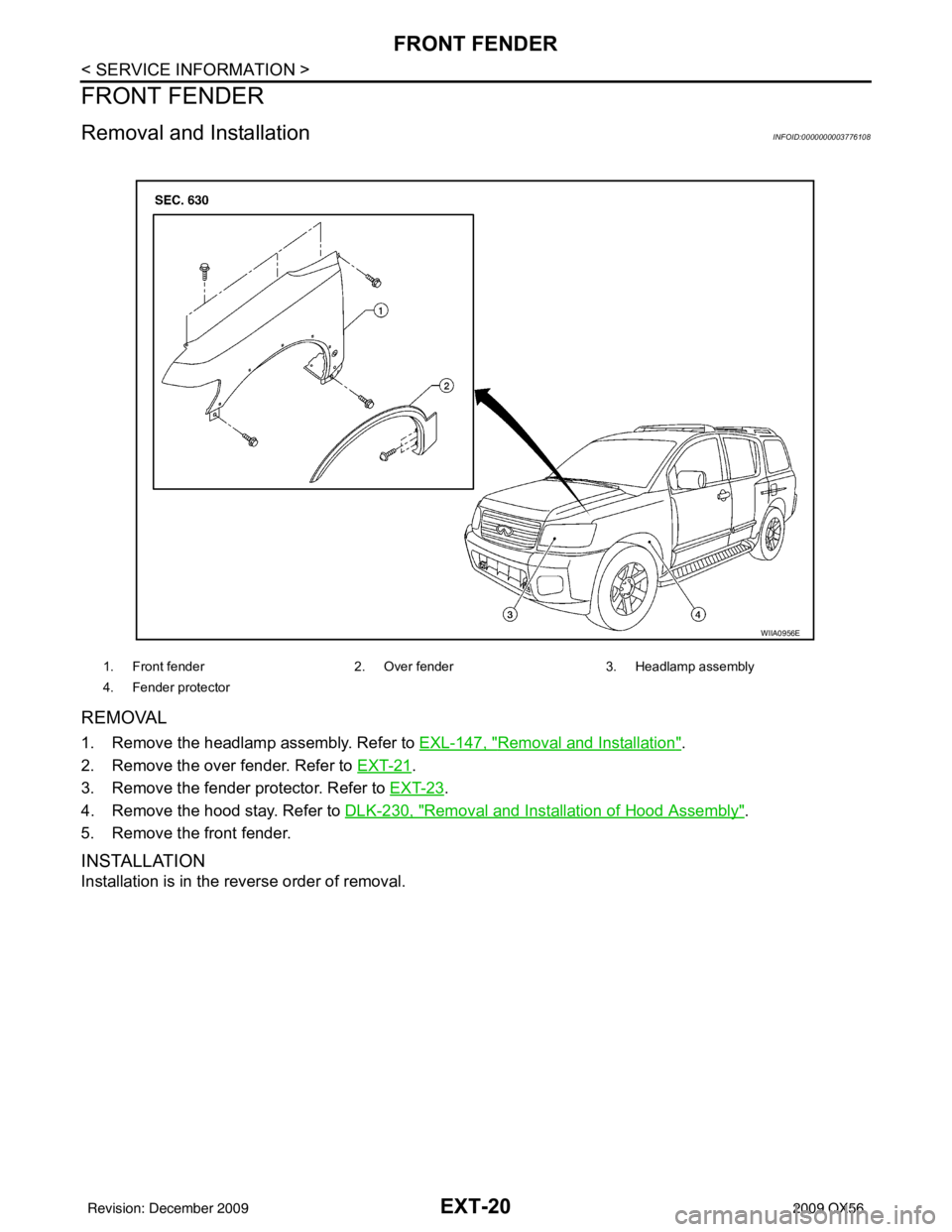
REMOVAL
1. Remove the headlamp assembly. Refer to EXL-147, "Removal and Installation".
2. Remove the over fender. Refer to EXT-21
.
3. Remove the fender protector. Refer to EXT-23
.
4. Remove the hood stay. Refer to DLK-230, "
Removal and Installation of Hood Assembly".
5. Remove the front fender.
INSTALLATION
Installation is in the reverse order of removal.
1. Front fender 2. Over fender3. Headlamp assembly
4. Fender protector
WIIA0956E
Revision: December 20092009 QX56
Page 2514 of 4171

INL-70
< SYMPTOM DIAGNOSIS >
INTERIOR LIGHTING SYSTEM SYMPTOMS
SYMPTOM DIAGNOSIS
INTERIOR LIGHTING SYSTEM SYMPTOMS
Symptom TableINFOID:0000000003776269
CAUTION:
Perform the self-diagnosis with CONSULT-III before the symptom diagnosis. Perform the trouble diag-
nosis if any DTC is detected.
Symptom Possible causeInspection item
All of the following lamps do not turn ON
• Front room/map lamp assembly
• Personal lamp 2nd and 3rd row
• Cargo room lamp
• Front and rear step lamps
• Vanity mirror lamps
• Ignition keyhole illumination
• Puddle lamps
•Foot lamps • Harness between BCM and each
interior room lamp
•BCM Battery saver output/power supply
circuit
Refer to
INL-15
.
Some or all of the following interior room lamps do not
turn ON/OFF
• Puddle lamps
• Front room/map lamp assembly
• Personal lamp 2nd row
• Personal lamp 3rd row • Harness between BCM and each
door switch
• Harness between BCM and each interior room lamp
•BCM Door switch circuit
Refer to
DLK-71
.
Interior room lamp control circuit
Refer to INL-17
.
Some or all of the following lamps do not turn ON/OFF
• Front step lamps
• Rear step lamps
•Foot lamps • Harness between BCM and step
lamps and foot lamps
•BCM Step lamp circuit
Refer to
INL-19
.
Cargo lamp does not turn ON/OFF • Harness between BCM and cargo
lamp
•BCM Cargo lamp co
ntrol circuit
Refer to INL-21
.
Ignition keyhole illumination does not turn ON/OFF • Harness between BCM and ignition
keyhole illumination
•BCM Ignition keyhole illumination control
circuit
Refer to
INL-23
.
Interior room lamp timer does not activate.
(It turns ON/ OFF when the door opens/closes.) —Check the interior room lamp setting.
Refer to
INL-12
.
Interior room lamp battery saver does not activate. —Check the interior room lamp battery
saver setting.
Refer to
INL-13
.
Revision: December 20092009 QX56
Page 2648 of 4171
![INFINITI QX56 2009 Factory Service Manual LAN
I-KEY BRANCH LINE CIRCUITLAN-79
< COMPONENT DIAGNOSIS > [CAN]
C
D
E
F
G H
I
J
K L
B A
O P
N
I-KEY BRANCH LINE CIRCUIT
Diagnosis ProcedureINFOID:0000000003776479
1.CHECK CONNECTOR
1. Turn the ignit INFINITI QX56 2009 Factory Service Manual LAN
I-KEY BRANCH LINE CIRCUITLAN-79
< COMPONENT DIAGNOSIS > [CAN]
C
D
E
F
G H
I
J
K L
B A
O P
N
I-KEY BRANCH LINE CIRCUIT
Diagnosis ProcedureINFOID:0000000003776479
1.CHECK CONNECTOR
1. Turn the ignit](/manual-img/42/57031/w960_57031-2647.png)
LAN
I-KEY BRANCH LINE CIRCUITLAN-79
< COMPONENT DIAGNOSIS > [CAN]
C
D
E
F
G H
I
J
K L
B A
O P
N
I-KEY BRANCH LINE CIRCUIT
Diagnosis ProcedureINFOID:0000000003776479
1.CHECK CONNECTOR
1. Turn the ignition switch OFF.
2. Disconnect the battery cabl e from the negative terminal.
3. Check the terminals and connectors of the Intelligent Key unit for damage, bend and loose connection (unit side and connector side).
Is the inspection result normal?
YES >> GO TO 2.
NO >> Repair the terminal and connector.
2.CHECK HARNESS FOR OPEN CIRCUIT
1. Disconnect the connector of Intelligent Key unit.
2. Check the resistance between the Intelli gent Key unit harness connector terminals.
Is the measurement value within the specification?
YES >> GO TO 3.
NO >> Repair the Intelligent Key unit branch line.
3.CHECK POWER SUPPLY AND GROUND CIRCUIT
Check the power supply and the ground circuit of the Intelligent Key unit. Refer to DLK-68, "
INTELLIGENT
KEY UNIT : Diagnosis Procedure".
Is the inspection result normal?
YES (Present error)>>Replace the Intelligent Key unit. Refer to SEC-111, "Removal and Installation".
YES (Past error)>>Error was detected in the Intelligent Key unit branch line.
NO >> Repair the power supply and the ground circuit.
Intelligent Key unit harness connector Resistance (Ω)
Connector No. Terminal No.
M70 2 3 Approx. 54 – 66
Revision: December 20092009 QX56
Page 2820 of 4171

MWI-98
< SYMPTOM DIAGNOSIS >
THE DOOR OPEN WARNING CONTINUES DISPLAYING, OR DOES NOT DIS-
PLAY
THE DOOR OPEN WARNING CONTIN UES DISPLAYING, OR DOES NOT
DISPLAY
DescriptionINFOID:0000000003776681
• The door open warning is displayed even though all of the doors are closed.
• The door open warning is not displayed even though a door is open.
Diagnosis ProcedureINFOID:0000000003776682
1.CHECK SELF-DIAGNOSIS OF COMBINATION METER
Select “METER/M&A” on CONSULT-II I and perform “SELF-DIAGNOSIS”.
Is the inspection result normal?
YES >> GO TO 2
NO >> Refer to MWI-62, "
DTC Index".
2.CHECK SELF-DIAGNOSIS OF BCM
Select “BCM” on CONSULT-III and perform “SELF-DIAGNOSIS”.
Is the inspection result normal?
YES >> GO TO 3
NO >> Refer to BCS-51, "
DTCIndex".
3.CHECK DOOR SWITCH SIGNAL CIRCUIT
Check the door switch signal circuit. Refer to DLK-71, "
Diagnosis Procedure".
Is the inspection result normal?
YES >> GO TO 4
NO >> Repair or replace malfunctioning parts.
4.CHECK GLASS HATCH AJAR SWITCH SIGNAL CIRCUIT
Check the glass hatch ajar switch signal circuit. Refer to DLK-129, "
Diagnosis Procedure".
Is the inspection result normal?
YES >> Replace combination meter. Refer to MWI-102, "Removal and Installation".
NO >> Repair or replace malfunctioning parts.
Revision: December 20092009 QX56
Page 2849 of 4171
![INFINITI QX56 2009 Factory Service Manual PCS-12
< FUNCTION DIAGNOSIS >[IPDM E/R]
DIAGNOSIS SYSTEM (IPDM E/R)
DIAGNOSIS SYSTEM (IPDM E/R)
Diagnosis DescriptionINFOID:0000000003776496
AUTO ACTIVE TEST
Description
In auto active test mode, the INFINITI QX56 2009 Factory Service Manual PCS-12
< FUNCTION DIAGNOSIS >[IPDM E/R]
DIAGNOSIS SYSTEM (IPDM E/R)
DIAGNOSIS SYSTEM (IPDM E/R)
Diagnosis DescriptionINFOID:0000000003776496
AUTO ACTIVE TEST
Description
In auto active test mode, the](/manual-img/42/57031/w960_57031-2848.png)
PCS-12
< FUNCTION DIAGNOSIS >[IPDM E/R]
DIAGNOSIS SYSTEM (IPDM E/R)
DIAGNOSIS SYSTEM (IPDM E/R)
Diagnosis DescriptionINFOID:0000000003776496
AUTO ACTIVE TEST
Description
In auto active test mode, the IPDM
E/R sends a drive signal to the follo wing systems to check their operation.
• Oil pressure low/coolant pressure high warning indicator
• Oil pressure gauge
• Rear window defogger
• Front wipers
• Tail, license and parking lamps
• Front fog lamps
• Headlamps (Hi, Lo)
• A/C compressor (magnetic clutch)
• Cooling fan
Operation Procedure
1. Close the hood and front door RH, and lift the wiper a rms from the windshield (to prevent windshield dam-
age due to wiper operation).
NOTE:
When auto active test is performed with hood opened, sprinkle water on windshield before hand.
2. Turn ignition switch OFF.
3. Turn the ignition switch ON and, within 20 seconds, press the front door switch LH 10 times. Then turn the ignition switch OFF.
4. Turn the ignition switch ON within 10 seconds. Af ter that the horn sounds once and the auto active test
starts.
5. After a series of the following operations is repeated 3 times, auto active test is completed.
NOTE:
When auto active test mode has to be cancelled halfway through test, turn ignition switch OFF.
CAUTION:
• If auto active test mode cannot be actuated, check door switch system. Refer to DLK-71, "
Descrip-
tion".
• Do not start the engine.
Inspection in Auto Active Test Mode
When auto active test mode is actuated, the following 7 steps are repeated 3 times.
Operation
sequence Inspection Location
Operation
1 Rear window defogger 10 seconds
2 Front wipers LO for 5 seconds → HI for 5 seconds
WKIA4655E
Revision: December 20092009 QX56
Page 2879 of 4171

PG-8
< BASIC INSPECTION >
INSPECTION AND ADJUSTMENT
INSPECTION AND ADJUSTMENT
ADDITIONAL SERVICE WHEN REMOVING BATTERY NEGATIVE TERMINAL
ADDITIONAL SERVICE WHEN REMOVING BATTERY NEGATIVE TERMINAL : Spe-
cial Repair Requirement
INFOID:0000000005864655
Required Procedure After Battery Disconnection
System ItemReference
Engine Control Idle Air Volume Learning Refer to EC-18
.
Brake Control Steering Angle Sensor Neutral Position Refer to BRC-8
.
Glasses, Window and Mirrors Power Window System Initialization Refer to TSB.
Body, Lock & Security Automatic Back Door Initialization Refer to DLK-9
.
Roof Sunroof Memory Reset/Initialization Refer to RF-5
.
Seats Automatic Drive Positioner System Initialization Refer to Owner's Manual.
Audio-Visual System Audio (Radio Preset)
Refer to Owner's Manual.
Navigation System Refer to Owner's Manual.
Rear View Monitor Guiding Line Adjustment Refer to AV- 7
.
Revision: December 20092009 QX56
Page 2955 of 4171

POWER WINDOW SYSTEMPWC-7
< FUNCTION DIAGNOSIS >
C
DE
F
G H
I
J
L
M A
B
PWC
N
O P
ANTI-PINCH OPERATION
Pinch foreign material in the door glass during AUTO-U P operation, and it is the anti-pinch function that low-
ers the door glass 150 mm (5.91 in) or 2 seconds when detected.
Encoder continues detecting the movement of power window motor and transmits to power window switch
as the encoder pulse signal while power window motor is operating.
Resistance is applied to the power window motor ro tation that changes the frequency of encoder pulse sig-
nal if foreign material is trapped in the door glass.
Front power window switch LH/RH and rear power wi ndow control unit LH/RH controls to lower the window
glass for 150 mm (5.91 in) or 2 seconds after it detects encoder pulse signal frequency change.
OPERATION CONDITION
When all door glass AUTO-UP operation is performed ( anti-pinch function does not operate just before the
door glass closes and is fully closed)
NOTE:
Depending on environment and driving conditions, if a similar impact or load is applied to the door glass, it
may lower.
KEY CYLINDER SWITCH OPERATION
Hold the door key cylinder to the LOCK or UNLOCK direction for more than 1 second to OPEN or CLOSE front
power windows when ignition switch is OFF. In addition, it stops when key position is moved to NEUTRAL
when operating.
OPERATION CONDITION
Ignition switch OFF
Hold door key cylinder to LOCK position for more than 1 second to perform CLOSE operation of the door
glass.
Hold door key cylinder to UNLOCK position for more than 1 second to perform OPEN operation of the door glass.
KEYLESS POWER WINDOW DOWN OPERATION
Front power windows open when the unlock button on Intelli gent Key is activated and kept pressed for more
than 3
(NOTE) seconds with the ignition switch OFF. The wi ndows keep opening if the unlock button is continu-
ously pressed.
The power window opening stops when the following operations are performed:
When the unlock button is kept pressed more than 15 seconds.
When the ignition switch is turned ON while the power window opening is operated.
When the unlock button is released.
While retained power operation is activated, ke yless power window down function cannot be operated.
NOTE:
Keyless power window down operation mode can be changed by “PW DOWN SET” mode in “WORK SUP-
PORT”. Refer to DLK-56, "CONSULT-III F unction (INTELLIGENT KEY)"
.
NOTE:
Use CONSULT-III to change settings.
MODE1 (3sec)/MODE2 (OFF)/MODE3 (5sec)
Revision: December 20092009 QX56
Page 2984 of 4171

PWC-36
< COMPONENT DIAGNOSIS >
DOOR KEY CYLINDER SWITCH
DOOR KEY CYLINDER SWITCH
DescriptionINFOID:0000000003776008
Main power window and door lock/unlock switch detects condition of the door key cylinder and transmits to
BCM as the LOCK or UNLOCK signals.
Component Function CheckINFOID:0000000003776009
1. CHECK DOOR KEY CYLINDER SWITCH INPUT SIGNAL
Check (“KEY CYL LK-SW”, “KEY CYL UN-SW”) in “DAT A MONITOR” mode for “POWER DOOR LOCK SYS-
TEM” with CONSULT-III. Refer to DLK-56, "CONSULT-III Function (INTELLIGENT KEY)"
.
Is the inspection result normal?
YES >> Key cylinder switch is OK.
NO >> Refer to PWC-36, "Diagnosis Procedure"
.
Diagnosis ProcedureINFOID:0000000003776010
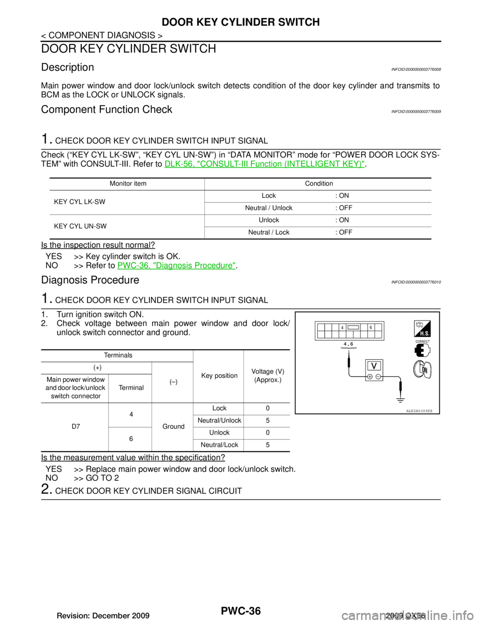
1. CHECK DOOR KEY CYLINDER SWITCH INPUT SIGNAL
1. Turn ignition switch ON.
2. Check voltage between main power window and door lock/ unlock switch connector and ground.
Is the measurement value within the specification?
YES >> Replace main power window and door lock/unlock switch.
NO >> GO TO 2
2. CHECK DOOR KEY CYLINDER SIGNAL CIRCUIT
Monitor item Condition
KEY CYL LK-SW Lock : ON
Neutral / Unlock : OFF
KEY CYL UN-SW Unlock : ON
Neutral / Lock : OFF
Te r m i n a l s
Key positionVoltage (V)
(Approx.)
(+)
(–)
Main power window
and door lock/unlock switch connector Te r m i n a l
D7 4
Ground Lock 0
Neutral/Unlock 5
6 Unlock 0
Neutral/Lock 5
ALKIA0309ZZ
Revision: December 20092009 QX56