Page 1051 of 4171
FRONT DOOR LOCKDLK-239
< ON-VEHICLE REPAIR > [WITH INTELLIGENT KEY SYSTEM]
C
D
E
F
G H
I
J
L
M A
B
DLK
N
O P
3. Remove the door side grommet, and the bolt (TORX T30) from the grommet hole.
4. While pulling the outside handle (1), remove the door key cylin- der assembly (LH) (2) or outside handle escutcheon (RH) (2).
5. Separate the key cylinder rod from the door key cylinder assembly (if equipped).
6. While pulling the outside handle, slide it toward rear of vehicle to remove as shown.
7. Remove the front gasket (1) and rear gasket (2). Torx bolt
5.3 N·m (0.54 kg-m, 47 in-lb)
PIIA3553E
ALKIA0899ZZ
ALKIA0900ZZ
ALKIA0893ZZ
Revision: December 20092009 QX56
Page 1052 of 4171
DLK-240
< ON-VEHICLE REPAIR >[WITH INTELLIGENT KEY SYSTEM]
FRONT DOOR LOCK
8. Remove the TORX bolts (T30) (1), and separate the door lock
assembly (2) from the door.
9. While pulling the outside handle bracket, slide it toward the front of the vehicle to remove it and the door lock assembly as shown.
⇐ : Front
10. Disconnect the door lock actuator electrical connector.
11. Separate the outside handle cable connection (1) from the out- side handle bracket.
INSTALLATION
Installation is in the reverse order of removal.
CAUTION:
To install the key cylinder rod, be sure to rotate the key cylinder rod holder until a click is felt.
Disassembly and AssemblyINFOID:0000000003775859
DOOR KEY CYLINDER ASSEMBLY
ALKIA0894ZZ
ALKIA0895ZZ
ALKIA0896ZZ
1. Door key cylinder assembly 2. Key cylinder assembly 3. Door key cylinder escutcheon
AWKIA1325ZZ
Revision: December 20092009 QX56
Page 1053 of 4171
FRONT DOOR LOCKDLK-241
< ON-VEHICLE REPAIR > [WITH INTELLIGENT KEY SYSTEM]
C
D
E
F
G H
I
J
L
M A
B
DLK
N
O P
Release the door key cylinder escutcheon pawls to remove the door key cylinder.
Revision: December 20092009 QX56
Page 1054 of 4171
DLK-242
< ON-VEHICLE REPAIR >[WITH INTELLIGENT KEY SYSTEM]
REAR DOOR LOCK
REAR DOOR LOCK
Component StructureINFOID:0000000003775860
Removal and InstallationINFOID:0000000005877754
REMOVAL
1. Remove the rear door finisher. Refer to
INT-11, "Removal and Installation".
2. Position aside the vapor barrier.
3. Remove door grommets, and remove outside handle nuts from grommet hole.
4. Remove outside handle and disconnect the cable.
5. Remove the door lock bolts, remove the door lock and disconnect the actuator connector.
INSTALLATION
Installation is in the reverse order of removal.
WIIA0892E
Revision: December 20092009 QX56
Page 1055 of 4171
BACK DOOR LOCKDLK-243
< ON-VEHICLE REPAIR > [WITH INTELLIGENT KEY SYSTEM]
C
D
E
F
G H
I
J
L
M A
B
DLK
N
O P
BACK DOOR LOCK
Power Back Door OpenerINFOID:0000000003775862
Removal
1. Disconnect the battery negative terminal. Refer to PG-76, "Removal and Installation".
2. Remove the LH luggage side upper. Refer to INT-19, "
Removal and Installation".
3. Disconnect the power back door motor electrical connector.
4. Disconnect the ball socket from the back door.
5. Remove the power back door motor assembly.
Installation
Installation is in the reverse order of removal.
WIIA0893E
Revision: December 20092009 QX56
Page 1056 of 4171
DLK-244
< ON-VEHICLE REPAIR >[WITH INTELLIGENT KEY SYSTEM]
BACK DOOR LOCK
Door Lock Assembly
INFOID:0000000003775863
Removal
1. Remove the lower back door trim panel. Refer to INT-21, "Removal and Installation".
2. Remove the weathershields.
3. Disconnect the back door lock electrical connectors.
4. Remove the back door lock assembly.
5. Disconnect the back door glass lock electrical connector.
6. Remove the back door glass lock.
Installation
Installation is in the reverse order of removal.
WIIA0894E
Revision: December 20092009 QX56
Page 1902 of 4171

ENGINE ASSEMBLYEM-79
< REMOVAL AND INSTALLATION >
C
DE
F
G H
I
J
K L
M A
EM
NP
O
1. Release the fuel pressure. Refer to
EC-487, "Fuel Pressure Check".
2. Drain the engine coolant. Refer to CO-11, "
Changing Engine Coolant".
3. Drain the engine oil. Refer to LU-9, "
Changing Engine Oil".
4. Disconnect the battery negative and positive terminal. Refer to PG-76, "
Removal and Installation".
5. Remove the engine hood. Refer to DLK-230, "
Removal and Installation of Hood Assembly".
6. Remove the cowl extension. Refer to EXT-18, "
Removal and Installation".
7. Remove the air duct and air cleaner case assembly. Refer to EM-25, "
Removal and Installation".
8. Remove the radiator assembly and hoses. Refer to CO-15, "
Removal and Installation".
NOTE:
To prevent possible A/T fluid drain from transmissi on opening, use appropriate cap to close off transmis-
sion opening during operation.
9. Remove the drive belt. Refer to EM-13, "
Removal and Installation".
10. Remove the fan blade. Refer to CO-18, "
Removal and Installation (Crankshaft Driven Type)".
11. Disconnect the engine room harness from the fuse box and set it aside.
12. Disconnect the ECM.
13. Disconnect the engine room harness from the engine side and set it aside.
14. Disconnect the engine harness grounds.
15. Disconnect the power steering reservoir t ank from the engine and move it aside.
16. Disconnect the power steering oil pump from the engine. Move it aside and secure it using suitable wire or rope. Refer to ST-26, "
Removal and Installation"
17. Remove the A/C compressor bolts and set the compressor aside. Refer to HA-31, "Removal and Installa-
tion for Compressor" (ATC).
18. Disconnect the brake booster vacuum hose.
19. Disconnect the EVAP line.
20. Disconnect the fuel hose at the engine side connection. Refer to EM-40, "
Removal and Installation".
21. Disconnect the heater hoses at the cowl, and in stall plugs to avoid leakage of engine coolant.
22. Remove the A/T oil level indicator and indicator tube upper bolts.
23. Remove the front final drive assembly (4WD only). Refer to DLN-215, "
Removal and Installation".
24. Remove the exhaust manifolds. Refer to EM-30, "
Removal and Installation".
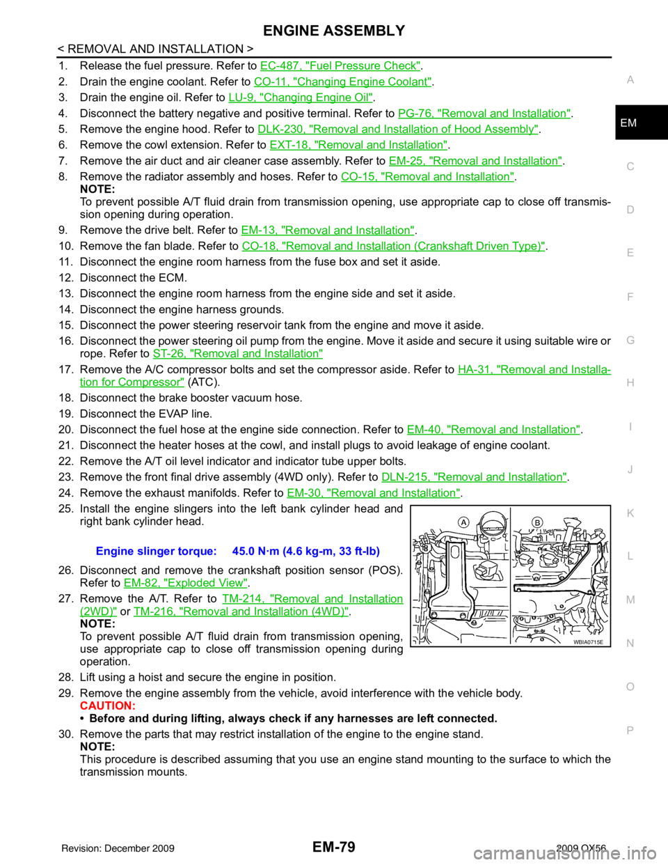
25. Install the engine slingers into the left bank cylinder head and right bank cylinder head.
26. Disconnect and remove the crankshaft position sensor (POS). Refer to EM-82, "
Exploded View".
27. Remove the A/T. Refer to TM-214, "
Removal and Installation
(2WD)" or TM-216, "Removal and Installation (4WD)".
NOTE:
To prevent possible A/T fluid drain from transmission opening,
use appropriate cap to close off transmission opening during
operation.
28. Lift using a hoist and secure the engine in position.
29. Remove the engine assembly from the vehicl e, avoid interference with the vehicle body.
CAUTION:
• Before and during lifting, always check if any harnesses are left connected.
30. Remove the parts that may restrict installation of the engine to the engine stand. NOTE:
This procedure is described assuming that you use an engine stand mounting to the surface to which the
transmission mounts. Engine slinger torque: 45.0 N·m (4.6 kg-m, 33 ft-lb)
WBIA0715E
Revision: December 20092009 QX56
Page 1973 of 4171

DIAGNOSIS SYSTEM (IPDM E/R)EXL-25
< FUNCTION DIAGNOSIS >
C
DE
F
G H
I
J
K
M A
B
EXL
N
O P
DIAGNOSIS SYSTEM (IPDM E/R)
Diagnosis DescriptionINFOID:0000000004215511
AUTO ACTIVE TEST
Description
In auto active test mode, the IPDM E/R sends a drive signal to the following systems to check their operation.
• Oil pressure low/coolant pressure high warning indicator
• Oil pressure gauge
• Rear window defogger
• Front wipers
• Tail, license and parking lamps
• Front fog lamps
• Headlamps (Hi, Lo)
• A/C compressor (magnetic clutch)
• Cooling fan
Operation Procedure
1. Close the hood and front door RH, and lift the wiper arms from the windshield (to prevent windshield dam-
age due to wiper operation).
NOTE:
When auto active test is performed with hood opened, sprinkle water on windshield before hand.
2. Turn ignition switch OFF.
3. Turn the ignition switch ON and, within 20 seconds, press the front door switch LH 10 times. Then turn the ignition switch OFF.
4. Turn the ignition switch ON within 10 seconds. Af ter that the horn sounds once and the auto active test
starts.
5. After a series of the following operations is repeated 3 times, auto active test is completed.
NOTE:
When auto active test mode has to be cancelled halfway through test, turn ignition switch OFF.
CAUTION:
• If auto active test mode cannot be actua ted, check door switch system. Refer to DLK-71, "
Descrip-
tion".
• Do not start the engine.
Inspection in Auto Active Test Mode
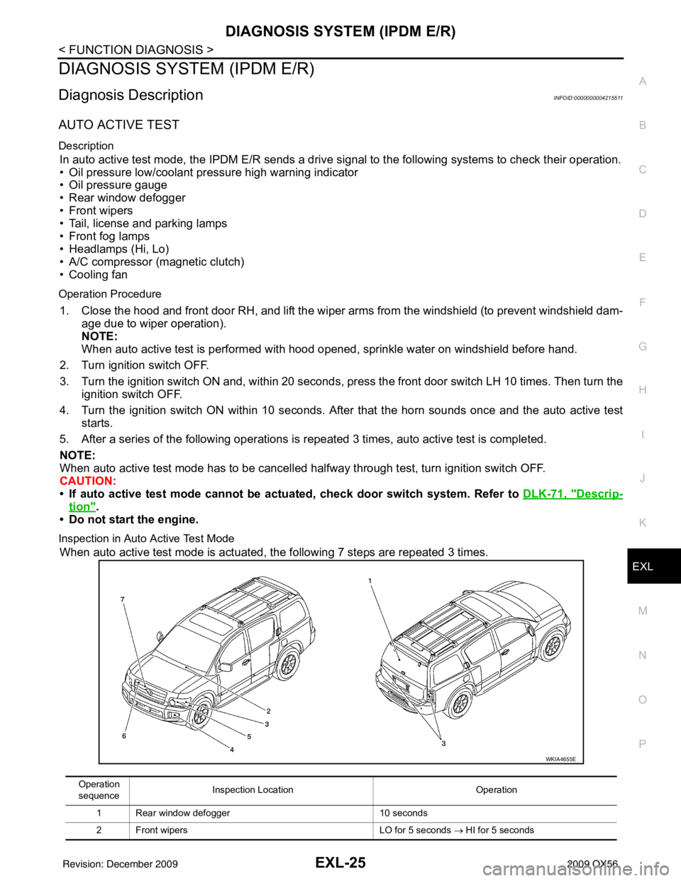
When auto active test mode is actuated, the following 7 steps are repeated 3 times.
Operation
sequence Inspection Location
Operation
1 Rear window defogger 10 seconds
2 Front wipers LO for 5 seconds → HI for 5 seconds
WKIA4655E
Revision: December 20092009 QX56