2009 INFINITI QX56 oil
[x] Cancel search: oilPage 2074 of 4171

EXL-126
< ECU DIAGNOSIS >
IPDM E/R (INTELLIGENT POWER DISTRIBUTION MODULE ENGINE ROOM)
41 Y/B Hood switch Input —Hood closed OFF
0V
Hood open ON Battery voltage
42 GR Oil pressure switch Input — Engine running
Battery voltage
Engine stopped 0V
43 L/Y Wiper auto stop signal Input ON or
START Wiper switch OFF, LO, INT Battery voltage
44 BR Daytime light relay
control Input ONDaytime light system active
0V
Daytime light system inactive Battery voltage
45 G/W Horn relay control Input ON When door locks are operated
using keyfob or Intelligent Key
(OFF
→ ON)* Battery voltage
→ 0V
46 GR Fuel pump relay con-
trol
Input —Ignition switch ON or START
0V
Ignition switch OFF or ACC Battery voltage
47 O Throttle control motor
relay control
Input —Ignition switch ON or START
0V
Ignition switch OFF or ACC Battery voltage
48 B/R Starter relay (inhibit
switch) InputON or
START Selector lever in "P" or "N"
0V
Selector lever any other posi-
tion Battery voltage
49 R/L Trailer tow relay Output ON Lighting
switch must
be in the 1st
positionOFF
0V
ON Battery voltage
50 W/R Front fog lamp (LH) Output ON or
START Lighting
switch must
be in the 2nd
position
(LOW beam
is ON) and
the front fog
lamp switch OFF
0V
ON Battery voltage
51 W/R Front fog lamp (RH) Output ON or
START Lighting
switch must
be in the 2nd
position
(LOW beam
is ON) and
the front fog
lamp switch OFF
0V
ON Battery voltage
52 L LH low beam head-
lamp Output — Lighting switch in 2nd position Battery voltage
54 R/Y RH low beam head-
lamp Output — Lighting switch in 2nd position Battery voltage
55 G LH high beam head-
lamp Output —Lighting switch in 2nd position
and placed in HIGH or PASS
position Battery voltage
56 L/W RH high beam head-
lamp Output —Lighting switch in 2nd position
and placed in HIGH or PASS
position Battery voltage
57 R/L Parking, license, and
tail lamp
Output ONLighting
swi
t
ch 1st po-
sition OFF
0V
ON Battery voltage
Te r m i n a l
Wire
color Signal name Signal
input/
output Measuring condition
Reference value(Approx.)
Igni-
tion
switch Operation or condition
Revision: December 20092009 QX56
Page 2080 of 4171

EXL-132
< ECU DIAGNOSIS >
IPDM E/R (INTELLIGENT POWER DISTRIBUTION MODULE ENGINE ROOM)
If No CAN Communication Is Available With BCM
IGNITION RELAY MALFUNCTION DETECTION FUNCTION
• IPDM E/R monitors the voltage at the contact circuit and excitation coil circuit of the ignition relay inside it.
• IPDM E/R judges the ignition relay error if the voltage differs between the contact circuit and the excitation
coil circuit.
• If the ignition relay cannot turn OFF due to contact seizure, it activates the tail lamp relay for 10 minutes to alert the user to the ignition relay malfunction when the ignition switch is turned OFF.
NOTE:
The tail lamp turns OFF when the ignition switch is turned ON.
FRONT WIPER CONTROL
IPDM E/R detects front wiper stop posit ion by a front wiper auto stop signal.
When a front wiper auto stop signal is in the conditions listed below, IPDM E/R stops power supply to wiper
after repeating a front wiper 10 second activation and 20 second stop five times.
NOTE:
This operation status can be confirmed on the IPDM E/R “DATA MONITOR” that displays “Block” for the item
“WIP PROT” while the wiper is stopped.
STARTER MOTOR PROTECTION FUNCTION
IPDM E/R turns OFF the starter control relay to protect the starter motor when the starter control relay remains
active for 90 seconds.
Control part Fail-safe in operation
Cooling fan • Turns ON the cooling fan relay when the ignition switch is turned ON
• Turns OFF the cooling fan relay when the ignition switch is turned OFF
Control part
Fail-safe in operation
Headlamp • Turns ON the headlamp low relay when the ignition switch is turned ON
• Turns OFF the headlamp low relay when the ignition switch is turned OFF
• Headlamp high relay OFF
•Parking lamps
• License plate lamps
• Tail lamps • Turns ON the tail lamp relay when the ignition switch is turned ON
• Turns OFF the tail lamp relay when the ignition switch is turned OFF
Front wiper • The status just before activation of fail-safe control is maintained until the ignition
switch is turned OFF while the front wiper is operating at LO or HI speed.
• The wiper is operated at LO speed until the ignition switch is turned OFF if the fail- safe control is activated while the front wipe r is set in the INT mode and the front wiper
motor is operating.
Rear window defogger Rear window defogger relay OFF
A/C compressor A/C relay OFF
Front fog lamps Front fog lamp relay OFF
Ignition switch Ignition relayTail lamp relay
ON ON —
OFF OFF —
Ignition switchFront wiper switch Auto stop signal
ON OFF
Front wiper stop position signal cannot be
input 10 seconds.
ON The signal does not change for 10 seconds.
Revision: December 20092009 QX56
Page 2091 of 4171

ADJUSTMENT AND INSPECTIONEXL-143
< ON-VEHICLE REPAIR >
C
DE
F
G H
I
J
K
M A
B
EXL
N
O P
ON-VEHICLE REPAIR
ADJUSTMENT AND INSPECTION
HEADLAMP
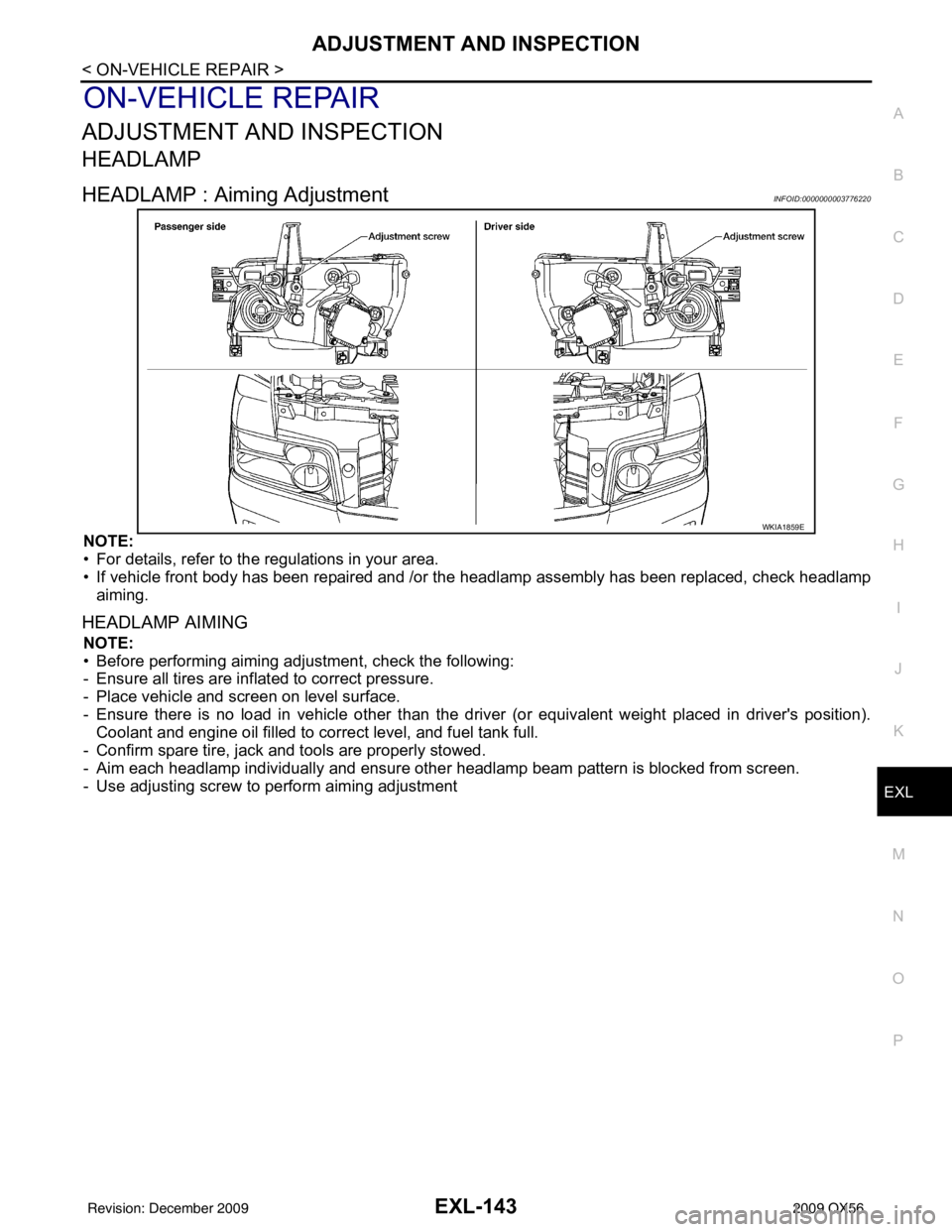
HEADLAMP : Aiming AdjustmentINFOID:0000000003776220
NOTE:
• For details, refer to the regulations in your area.
• If vehicle front body has been repaired and /or the headlamp assembly has been replaced, check headlamp
aiming.
HEADLAMP AIMING
NOTE:
• Before performing aiming adjustment, check the following:
- Ensure all tires are inflated to correct pressure.
- Place vehicle and screen on level surface.
- Ensure there is no load in vehicle other than the driver (or equivalent weight placed in driver's position). Coolant and engine oil filled to correct level, and fuel tank full.
- Confirm spare tire, jack and tools are properly stowed.
- Aim each headlamp individually and ensure other headlamp beam pattern is blocked from screen.
- Use adjusting screw to perform aiming adjustment
WKIA1859E
Revision: December 20092009 QX56
Page 2093 of 4171

ADJUSTMENT AND INSPECTIONEXL-145
< ON-VEHICLE REPAIR >
C
DE
F
G H
I
J
K
M A
B
EXL
N
O P
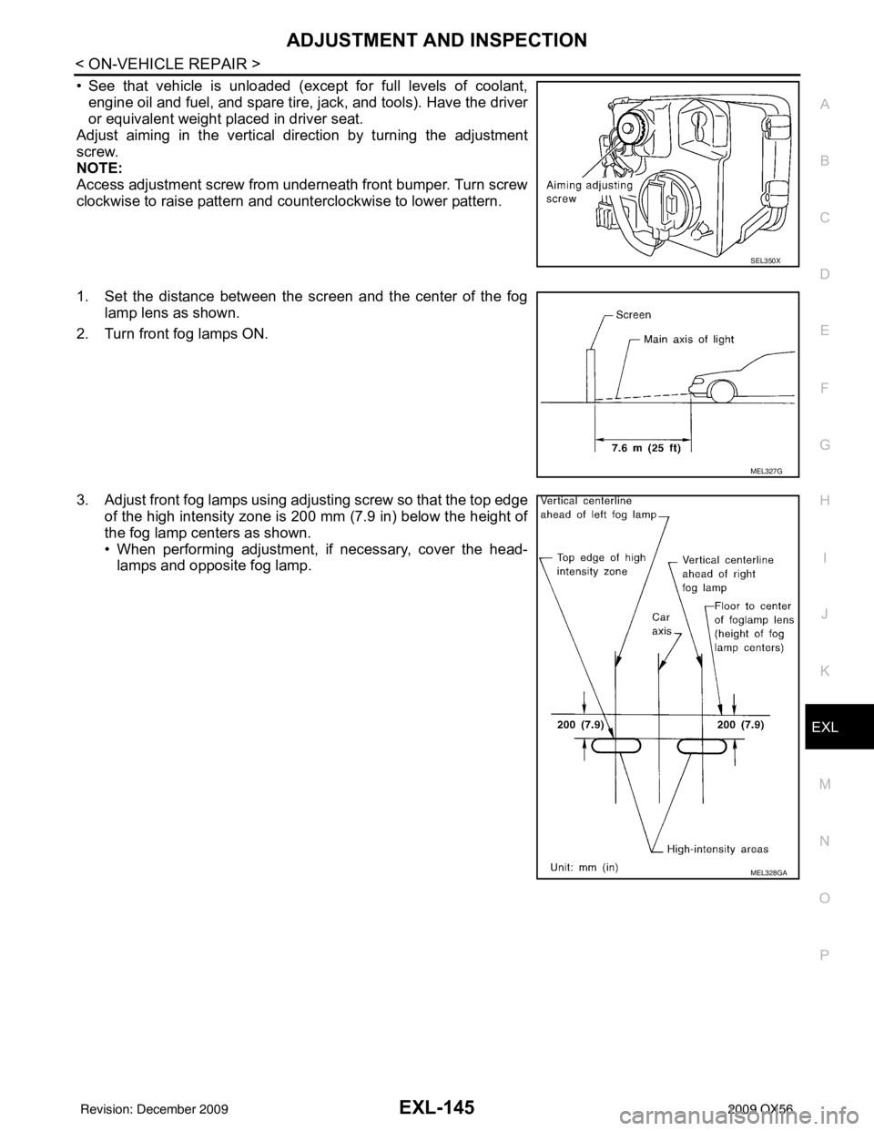
• See that vehicle is unloaded (except for full levels of coolant, engine oil and fuel, and spare tire, jack, and tools). Have the driver
or equivalent weight placed in driver seat.
Adjust aiming in the vertical direction by turning the adjustment
screw.
NOTE:
Access adjustment screw from underneath front bumper. Turn screw
clockwise to raise pattern and c ounterclockwise to lower pattern.
1. Set the distance between the screen and the center of the fog lamp lens as shown.
2. Turn front fog lamps ON.
3. Adjust front fog lamps using adjusting screw so that the top edge of the high intensity zone is 200 mm (7.9 in) below the height of
the fog lamp centers as shown.
• When performing adjustment, if necessary, cover the head-lamps and opposite fog lamp.
SEL350X
MEL327G
MEL328GA
Revision: December 20092009 QX56
Page 2094 of 4171

EXL-146
< REMOVAL AND INSTALLATION >
HEADLAMP
REMOVAL AND INSTALLATION
HEADLAMP
Bulb ReplacementINFOID:0000000003776222
CAUTION:
• Disconnect battery negative terminal before touching xenon bulb or headlamp wiring harness
assembly.
• Turn headlamp switch OFF before disconnecting headlamp harness connector.
• Do not touch bulb by hand right after being turned off. Burning may result.
• Do not touch the glass of bulb directly by hand. Keep grease and other oily substances away from it.
• Do not turn xenon bulb ON wh en xenon bulb is removed from front combination lamp assembly.
• After installing the bulb, be sure to install the bulb socket securely to ensure watertightness.
• Do not leave bulb out of front combination lamp assembly for a long time because dust, moisture,
smoke, etc. may affect the performa nce of the lamp. When replacing bulb, be sure to replace it with a
new one.
HEADLAMP (OUTER SIDE), FOR LOW BEAM
Removal
1. Position fender protector aside.
2. Turn headlamp switch OFF.
3. Disconnect battery negative terminal.
4. Remove ballast.
5. Disconnect headlamp electrical connector.
6. Release bulb retaining spring and pull bulb straight out.
Installation
Installation is in the reverse order of removal.
HEADLAMP (INNER SIDE), FOR HIGH BEAM
Removal
1. Turn headlamp switch OFF.
2. Disconnect headlamp electrical connector.
3. Turn the bulb counterclockwise to remove it.
Installation
Installation is in the reverse order of removal.
FRONT PARKING LAMP (INNER OR OUTER)
Removal
1. Turn the bulb socket counterclockwise to unlock it.
2. Pull the bulb to remove it from the socket.
Installation
Installation is in the reverse order of removal.
SIDE MARKER LAMP (FRONT)
Removal
1. Position fender protector aside.
2. Turn the side marker lamp (front) bulb socket counterclockwise and remove side marker lamp (front) bulb socket.
3. Pull to remove side marker lamp (front) fr om the side marker lamp (front) bulb socket.
Installation
Installation is in the reverse order of removal.
Revision: December 20092009 QX56
Page 2095 of 4171

HEADLAMPEXL-147
< REMOVAL AND INSTALLATION >
C
DE
F
G H
I
J
K
M A
B
EXL
N
O P
Removal and InstallationINFOID:0000000003776223
FRONT COMBINATION LAMP ASSEMBLY
CAUTION:
• Disconnect battery negative terminal before touc hing xenon bulb or headlamp wiring harness
assembly.
• Turn headlamp switch OFF before di sconnecting headlamp harness connector.
• Do not touch bulb by hand right after being turned off. Burning may result.
• Do not touch the glass of bulb directly by hand. Keep grease and other oily substances away from it.
• Do not turn xenon bulb ON when xenon bulb is removed fr om front combination lamp assembly.
• After installing the bu lb, be sure to install the bulb socket securely to ensure watertightness.
• Do not leave bulb out of front combination lamp assembly for a lo ng time because dust, moisture,
smoke, etc. may affect the performance of the lamp. When replacing bulb, be sure to replace it with a
new one.
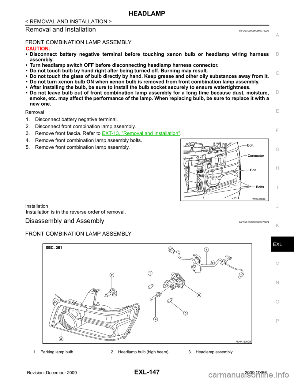
Removal
1. Disconnect battery negative terminal.
2. Disconnect front combination lamp assembly.
3. Remove front fascia. Refer to EXT-13, "
Removal and Installation".
4. Remove front combination lamp assembly bolts.
5. Remove front combination lamp assembly.
Installation
Installation is in the reverse order of removal.
Disassembly and AssemblyINFOID:0000000003776224
FRONT COMBINATION LAMP ASSEMBLY
WKIA1860E
1. Parking lamp bulb 2. Headlamp bulb (high beam) 3. Headlamp assembly
ALKIA1536GB
Revision: December 20092009 QX56
Page 2098 of 4171

EXL-150
< REMOVAL AND INSTALLATION >
FRONT FOG LAMP
FRONT FOG LAMP
Bulb ReplacementINFOID:0000000003776226
FRONT FOG LAMP
Removal
1. Remove the front turn/fog lamp assembly. Refer to EXL-150, "Removal and Installation".
2. Turn the bulb cover counterclockwise to remove it.
3. Unlatch retaining spring.
4. Remove bulb and disconnect the connector. CAUTION:
• Do not touch the glass of bulb directly by hand. Keep
grease and other oily substances away from it. Do not
touch bulb by hand while it is lit or right after being turned
off. Burning may result.
• Do not leave bulb out of fog la mp reflector for a long time
because dust, moisture smoke, etc. may affect the perfor-
mance of fog lamp. When replacing bulb, be sure to
replace it with new one.
Installation
Installation is in the reverse order of removal.
Removal and InstallationINFOID:0000000003776227
FRONT FOG LAMP
The fog lamp is a semi-sealed beam type which uses a replaceable halogen bulb.
CAUTION:
• Do not leave fog lamp assembly without bulb for a long period of time. Dust, moisture, smoke, etc. entering the fog lamp body may affect the perf ormance. Remove the bulb from the headlamp assem-
bly just before replacement bulb is installed.
• Grasp only the plastic base when handling the bulb. Never touch the glass envelope. Touching the
glass could significantly affect the bulb life and/or fog lamp performance.
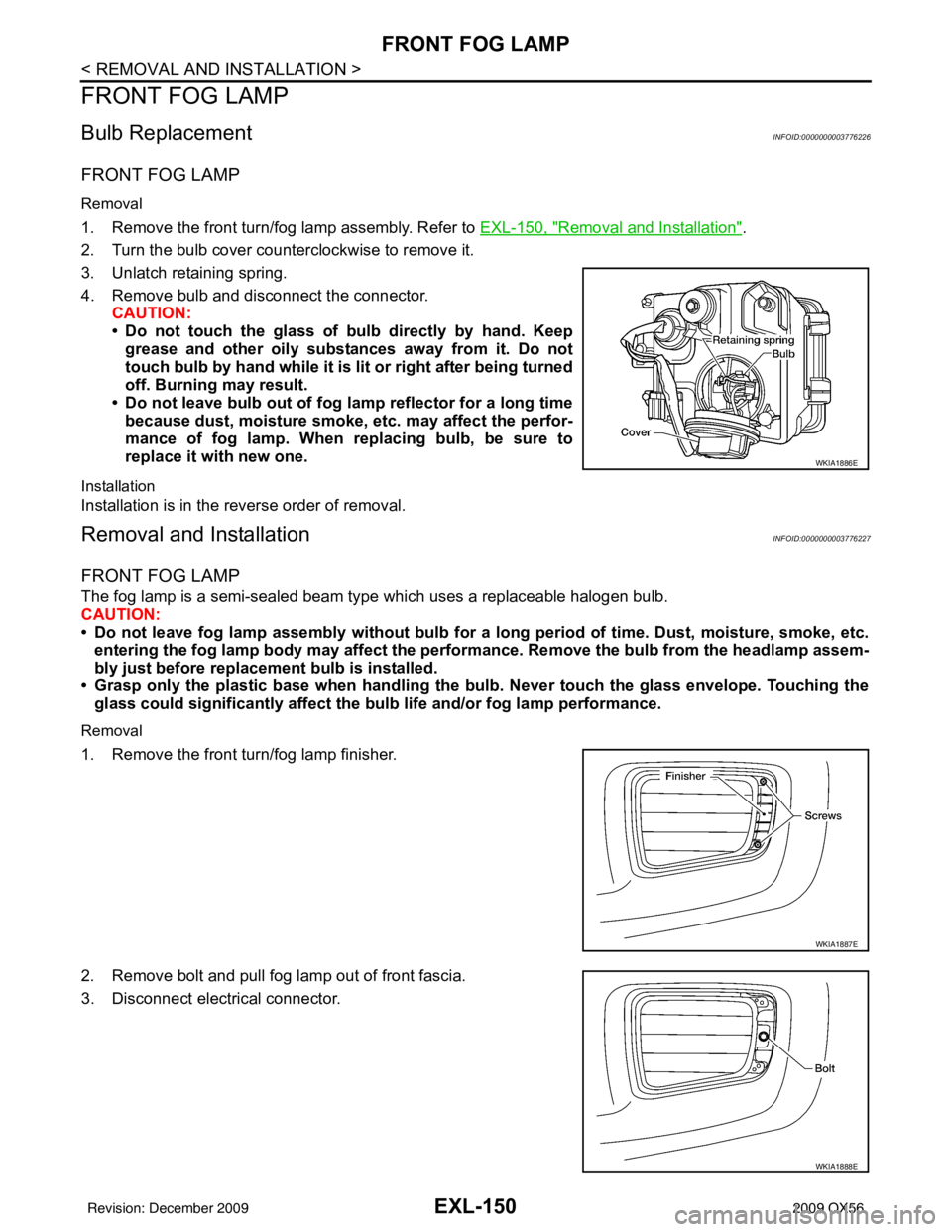
Removal
1. Remove the front turn/fog lamp finisher.
2. Remove bolt and pull fog lamp out of front fascia.
3. Disconnect electrical connector.
WKIA1886E
WKIA1887E
WKIA1888E
Revision: December 20092009 QX56
Page 2107 of 4171

EXT-1
BODY EXTERIOR, DOORS, ROOF & VEHICLE SECURITY
C
DE
F
G H
I
J
L
M
SECTION EXT
A
B
EXT
N
O P
CONTENTS
EXTERIOR
SERVICE INFORMATION .. ..........................2
PRECAUTIONS .............................................. .....2
Precaution for Supplemental Restraint System
(SRS) "AIR BAG" and "SEAT BELT PRE-TEN-
SIONER" ............................................................. ......
2
Precaution Necessary for Steering Wheel Rota-
tion After Battery Disconnect ............................... ......
2
Service Notice ...........................................................3
PREPARATION ...................................................4
Special Service Tool ........................................... ......4
Commercial Service Tool ..........................................4
SQUEAK AND RATTLE TROUBLE DIAG-
NOSES ................................................................
5
Work Flow ........................................................... ......5
Generic Squeak and Rattle Troubleshooting ............7
Diagnostic Worksheet ...............................................9
CLIP AND FASTENER .......................................11
Description .......................................................... ....11
FRONT BUMPER ...............................................13
Removal and Installation .........................................13
REAR BUMPER ............................................. ....15
Removal and Installation .........................................15
FRONT GRILLE .................................................17
Removal and Installation ..................................... ....17
COWL TOP .......................................................18
Removal and Installation .........................................18
FRONT FENDER ...............................................20
Removal and Installation .........................................20
OVER FENDER .................................................21
Removal and Installation .........................................21
FENDER PROTECTOR ....................................23
Removal and Installation .........................................23
LICENSE LAMP FINISHER ..............................24
Removal and Installation .........................................24
RUNNING BOARDS .........................................25
Removal and Installation .........................................25
REAR SPOILER ................................................26
Removal and Installation .........................................26
ROOF RACK .....................................................27
Removal and Installation ..................................... ....27
DOOR OUTSIDE MOLDING .............................28
Removal and Installation .........................................28
SIDE GUARD MOLDING ..................................30
Removal and Installation ..................................... ....30
Revision: December 20092009 QX56