2009 INFINITI QX56 wheel torque
[x] Cancel search: wheel torquePage 2144 of 4171
WHEEL HUBFAX-7
< REMOVAL AND INSTALLATION >
CEF
G H
I
J
K L
M A
B
FA X
N
O P
REMOVAL AND INSTALLATION
WHEEL HUB
Removal and InstallationINFOID:0000000005889823
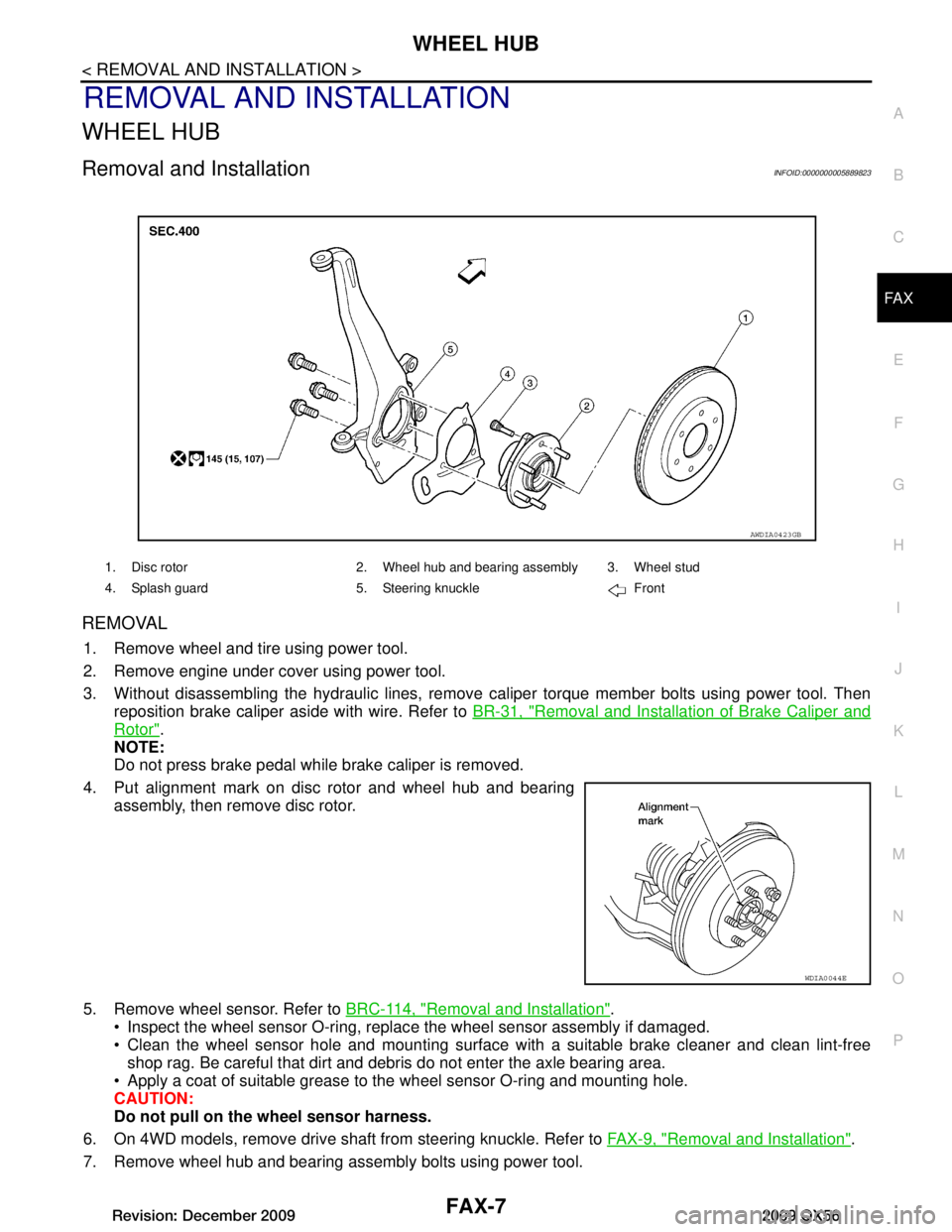
REMOVAL
1. Remove wheel and tire using power tool.
2. Remove engine under cover using power tool.
3. Without disassembling the hydraulic lines, remove caliper torque member bolts using power tool. Then reposition brake caliper aside with wire. Refer to BR-31, "Removal and Installation of Brake Caliper and
Rotor".
NOTE:
Do not press brake pedal while brake caliper is removed.
4. Put alignment mark on disc rotor and wheel hub and bearing assembly, then remove disc rotor.
5. Remove wheel sensor. Refer to BRC-114, "Removal and Installation"
.
Inspect the wheel sensor O-ring, replac e the wheel sensor assembly if damaged.
Clean the wheel sensor hole and mounting surface with a suitable brake cleaner and clean lint-free shop rag. Be careful that dirt and debr is do not enter the axle bearing area.
Apply a coat of suitable grease to t he wheel sensor O-ring and mounting hole.
CAUTION:
Do not pull on th e wheel sensor harness.
6. On 4WD models, remove drive shaft from steering knuckle. Refer to FAX-9, "Removal and Installation"
.
7. Remove wheel hub and bearing assembly bolts using power tool.
1. Disc rotor 2. Wheel hub and bearing assembly 3. Wheel stud
4. Splash guard 5. Steering knuckle Front
AWDIA0423GB
WDIA0044E
Revision: December 20092009 QX56
Page 2176 of 4171
FSU-6
< ON-VEHICLE MAINTENANCE >
ON-VEHICLE SERVICE
ON-VEHICLE MAINTENANCE
ON-VEHICLE SERVICE
Front Suspension PartsINFOID:0000000003772269
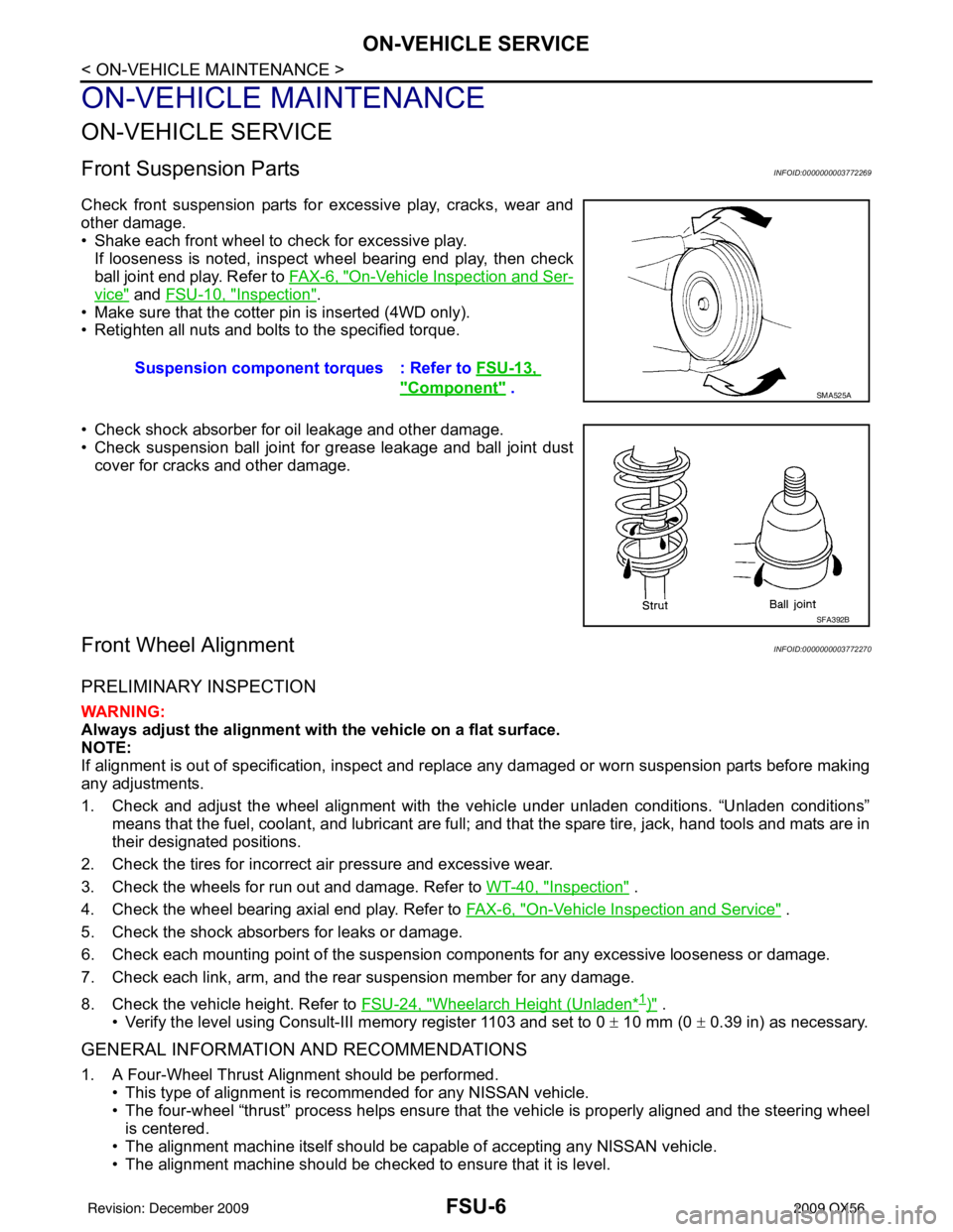
Check front suspension parts for excessive play, cracks, wear and
other damage.
• Shake each front wheel to check for excessive play.If looseness is noted, inspect wheel bearing end play, then check
ball joint end play. Refer to FA X - 6 , "
On-Vehicle Inspection and Ser-
vice" and FSU-10, "Inspection".
• Make sure that the cotter pin is inserted (4WD only).
• Retighten all nuts and bolts to the specified torque.
• Check shock absorber for oil leakage and other damage.
• Check suspension ball joint for grease leakage and ball joint dust cover for cracks and other damage.
Front Wheel AlignmentINFOID:0000000003772270
PRELIMINARY INSPECTION
WARNING:
Always adjust the alignment with the vehicle on a flat surface.
NOTE:
If alignment is out of specificat ion, inspect and replace any damaged or worn suspension parts before making
any adjustments.
1. Check and adjust the wheel alignment with the vehicle under unladen conditions. “Unladen conditions”
means that the fuel, coolant, and lubricant are full; and that the spare tire, jack, hand tools and mats are in
their designated positions.
2. Check the tires for incorrect air pressure and excessive wear.
3. Check the wheels for run out and damage. Refer to WT-40, "
Inspection" .
4. Check the wheel bearing axial end play. Refer to FA X - 6 , "
On-Vehicle Inspection and Service" .
5. Check the shock absorbers for leaks or damage.
6. Check each mounting point of the suspension components for any excessive looseness or damage.
7. Check each link, arm, and the rear suspension member for any damage.
8. Check the vehicle height. Refer to FSU-24, "
Wheelarch Height (Unladen*1)" .
• Verify the level using Consult-III memory register 1103 and set to 0 ± 10 mm (0 ± 0.39 in) as necessary.
GENERAL INFORMATION AND RECOMMENDATIONS
1. A Four-Wheel Thrust Alignment should be performed.
• This type of alignment is recommended for any NISSAN vehicle.
• The four-wheel “thrust” process helps ensure that the vehicle is properly aligned and the steering wheel
is centered.
• The alignment machine itself should be ca pable of accepting any NISSAN vehicle.
• The alignment machine should be checked to ensure that it is level. Suspension component
torques : Refer to FSU-13,
"Component" . SMA525A
SFA392B
Revision: December 20092009 QX56
Page 2190 of 4171
FSU-20
< REMOVAL AND INSTALLATION >
KNUCKLE
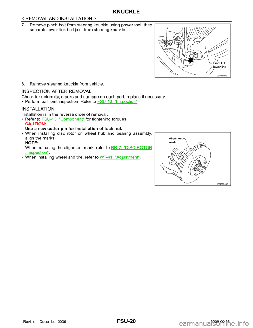
7. Remove pinch bolt from steering knuckle using power tool, thenseparate lower link ball joint from steering knuckle.
8. Remove steering knuckle from vehicle.
INSPECTION AFTER REMOVAL
Check for deformity, cracks and damage on each part, replace if necessary.
• Perform ball joint inspection. Refer to FSU-10, "
Inspection".
INSTALLATION
Installation is in the reverse order of removal.
• Refer to FSU-13, "
Component" for tightening torques.
CAUTION:
Use a new cotter pin for installation of lock nut.
• When installing disc rotor on wheel hub and bearing assembly, align the marks.
NOTE:
When not using the alignment mark, refer to BR-7, "
DISC ROTOR
: Inspection".
• When installing wheel and tire, refer to WT-41, "
Adjustment".
LEIA0097E
WDIA0044E
Revision: December 20092009 QX56
Page 2194 of 4171
FSU-24
< SERVICE DATA AND SPECIFICATIONS (SDS)
SERVICE DATA AND SPECIFICATIONS (SDS)
*2: Target value 37° 31 ′ (37.52 °)
*3: Target value 33 ° 59 ′ (33.98 °)
*4: Target value 37 ° 44 ′ (37.73 °)
*5: Target value 33 ° 29 ′ (33.48 °)
*6 Some vehicles may not be equipped with straight (non-adjustable) lower link bolts and washers. In order to adjust camber and caster
on these vehicles, first replace the lower link bolts and washers with adjustable (cam) bolts and washers
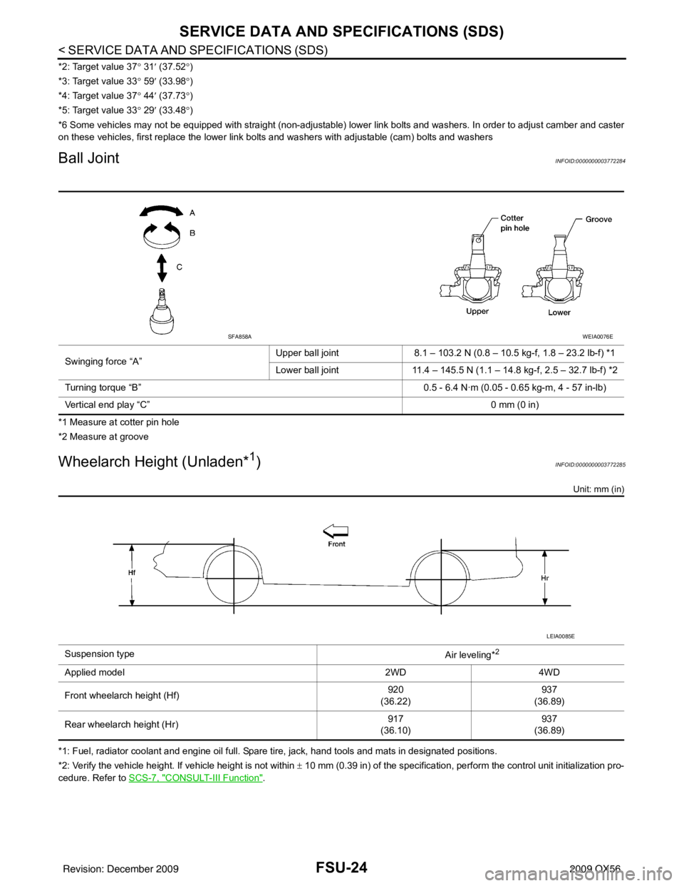
Ball JointINFOID:0000000003772284
*1 Measure at cotter pin hole
*2 Measure at groove
Wheelarch Height (Unladen*1)INFOID:0000000003772285
Unit: mm (in)
*1: Fuel, radiator coolant and engine oil full. Spare tire, jack, hand tools and mats in designated positions.
*2: Verify the vehicle height. If vehicle height is not within ± 10 mm (0.39 in) of the specification, perform the control unit initialization pro-
cedure. Refer to SCS-7, "
CONSULT-III Function".
Swinging force “A”
Upper ball joint
8.1 – 103.2 N (0.8 – 10.5 kg-f, 1.8 – 23.2 lb-f) *1
Lower ball joint 11.4 – 145.5 N (1.1 – 14.8 kg-f, 2.5 – 32.7 lb-f) *2
Turning torque “B” 0.5 - 6.4 N·m (0.05 - 0.65 kg-m, 4 - 57 in-lb)
Vertical end play “C” 0 mm (0 in)
SFA858AWEIA0076E
Suspension type
Air leveling*2
Applied model2WD4WD
Front wheelarch height (Hf) 920
(36.22) 937
(36.89)
Rear wheelarch height (Hr) 917
(36.10) 937
(36.89)
LEIA0085E
Revision: December 20092009 QX56
Page 2195 of 4171
GI-1
GENERAL INFORMATION
C
DE
F
G H
I
J
K L
M B
GI
SECTION GI
N
O P
CONTENTS
GENERAL INFORMATION
HOW TO USE THIS MANU AL ......................3
HOW TO USE THIS MANUAL ....................... .....3
Description .......................................................... ......3
Terms ........................................................................3
Units ..........................................................................3
Contents ....................................................................3
Relation between Illustrations and Descriptions .......4
Components ..............................................................4
HOW TO FOLLOW TROUBLE DIAGNOSES .....6
Description ................................................................6
How to Follow Test Groups in Trouble Diagnosis ......6
Key to Symbols Signifying Measurements or Pro-
cedures ............................................................... ......
7
HOW TO READ WIRING DIAGRAMS ................9
Connector symbols ............................................. ......9
Sample/wiring diagram -example- ...........................10
Description ..............................................................11
ABBREVIATIONS .......................................... ....13
Abbreviation List .................................................. ....13
TIGHTENING TORQUE OF STANDARD
BOLTS ................................................................
14
Tightening Torque Table .........................................14
RECOMMENDED CHEMICAL PRODUCTS
AND SEALANTS ............................................ ....
15
Recommended Chemical Products and Sealants ....15
TERMINOLOGY .................................................16
SAE J1930 Terminology List ............................... ....16
FEATURES OF NEW MODEL .....................20
IDENTIFICATION INFORMATION .....................20
Model Variation ................................................... ....20
Identification Number ..............................................21
Identification Plate ...................................................22
Dimensions .............................................................23
Wheels & Tires .................................................... ....23
PRECAUTION ..............................................24
PRECAUTIONS .................................................24
Description ........................................................... ....24
Precaution for Supplemental Restraint System
(SRS) "AIR BAG" and "SEAT BELT PRE-TEN-
SIONER" .................................................................
24
Precaution Necessary for Steering Wheel Rota-
tion After Battery Disconnect ...................................
24
Procedures without Cowl Top Cover .......................25
General Precautions ................................................25
Three Way Catalyst .................................................27
Precaution for Fuel (Unleaded Premium Gasoline
Recommended) .......................................................
27
Multiport Fuel Injection System or Engine Control
System .....................................................................
27
Hoses ......................................................................27
Engine Oils ..............................................................28
Air Conditioning .......................................................29
LIFTING POINT .................................................30
Pantograph Jack ......................................................30
Garage Jack and Safety Stand ................................30
2-Pole Lift ................................................................30
TOW TRUCK TOWING .....................................32
Tow Truck Towing ...................................................32
Vehicle Recovery (Freeing a stuck vehicle) ............33
BASIC INSPECTION ...................................34
SERVICE INFORMATION FOR ELECTRICAL
INCIDENT ..........................................................
34
Work Flow ............................................................ ....34
Control Units and Electrical Parts ............................34
How to Check Terminal ...........................................35
Intermittent Incident ............................................. ....38
Circuit Inspection .....................................................41
CONSULT-III CHECKING SYSTEM .................46
Revision: December 20092009 QX56
Page 2701 of 4171
MA-28
< ON-VEHICLE MAINTENANCE >
CHASSIS AND BODY MAINTENANCE
1. Remove the filler plug and gasket from the rear final driveassembly.
2. Fill the rear final drive assembly with new differential gear oil until the level reaches the specified level near the filler plug hole.
3. Install the filler plug with a new gasket on it to the rear final drive assembly. Tighten to the specified torque. Refer to DLN-253,
"Disassembly and Assembly".
CAUTION:
Do not reuse gasket.
Balancing WheelsINFOID:0000000004215547
BALANCING WHEELS (ADHESIVE WEIGHT TYPE)
Preparation Before Adjustment
Remove inner and outer balance weights from the road wheel using releasing agent, remove double-faced
adhesive tape from the road wheel.
CAUTION:
• Be careful not scratch the road wheel during removal.
• After removing double-faced adhesive tape, wipe clean traces of releasing agent from the road
wheel.
Wheel Balance Adjustment
CAUTION:
• Use center hole cone-type clamping machines due to clad wheels.
• If a balancer machine has an adhesive weight mode se tting, select the adhesive weight mode setting and
skip Step 2. below. If a balancer machine only has the clip-on (rim flange) weight mode setting, follow Step 2.
to calculate the correct size adhesive weight.
1. Set road wheel on balancer machine using the center hole as a guide. Start the balancer machine.
2. For tire balance machines that only have a clip-on (rim flange) weight mode setting, follow this step to cal- culate the correct size adhesive weight to use. When inner and outer imbalance values are shown on the
balancer machine indicator, multiply outer imbalance value by 5/3 (1.67) to determine balance weight that
should be used. Select the outer balance weight with a value closest to the calculated value above and
install in to the designated outer position of, or at the designated angle in relation to the road wheel.
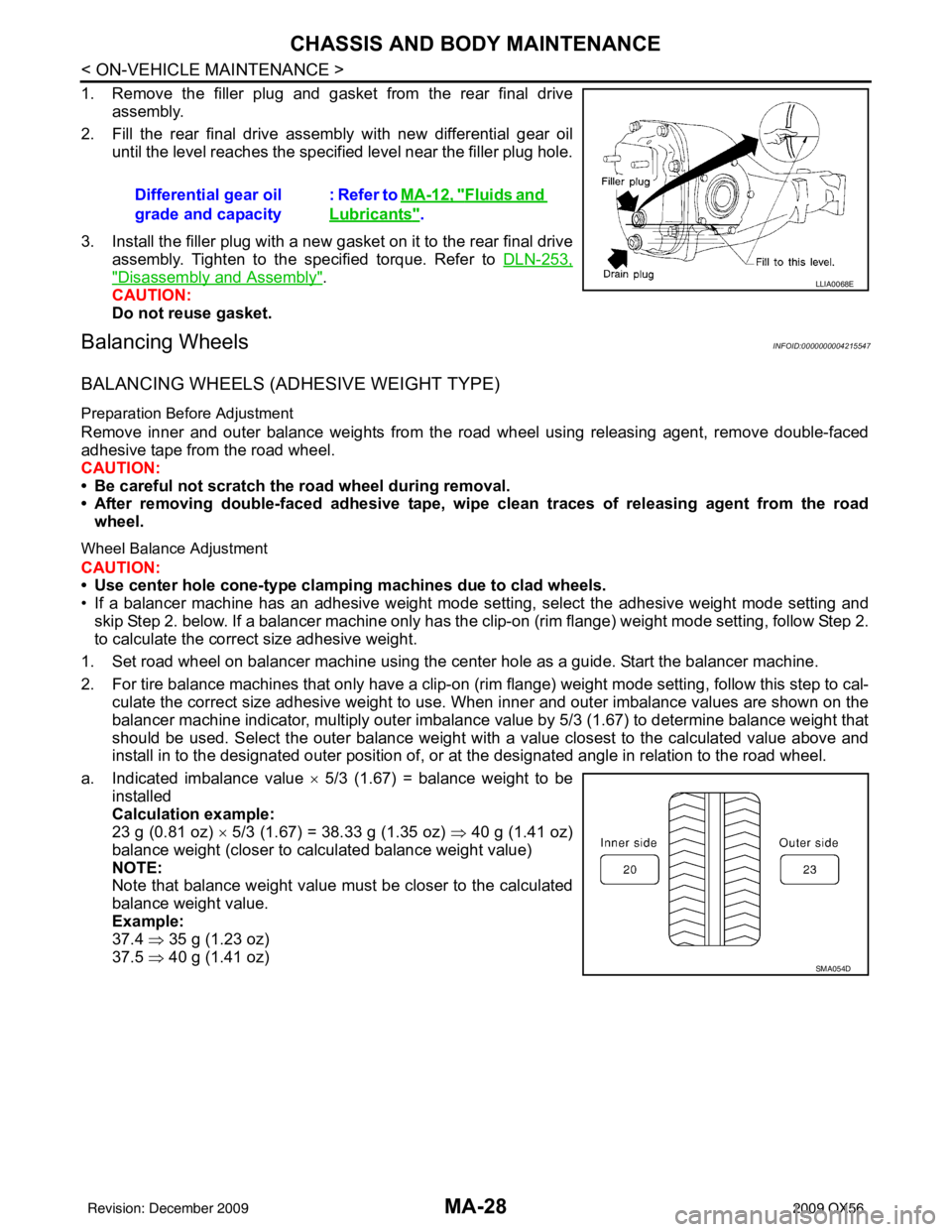
a. Indicated imbalance value × 5/3 (1.67) = balance weight to be
installed
Calculation example:
23 g (0.81 oz) × 5/3 (1.67) = 38.33 g (1.35 oz) ⇒ 40 g (1.41 oz)
balance weight (closer to calculated balance weight value)
NOTE:
Note that balance weight value must be closer to the calculated
balance weight value.
Example:
37.4 ⇒ 35 g (1.23 oz)
37.5 ⇒ 40 g (1.41 oz)
Differential gear oil
grade and capacity
: Refer to MA-12, "
Fluids and
Lubricants".
LLIA0068E
SMA054D
Revision: December 20092009 QX56
Page 2702 of 4171
CHASSIS AND BODY MAINTENANCEMA-29
< ON-VEHICLE MAINTENANCE >
C
DE
F
G H
I
J
K L
M B
MA
N
O A
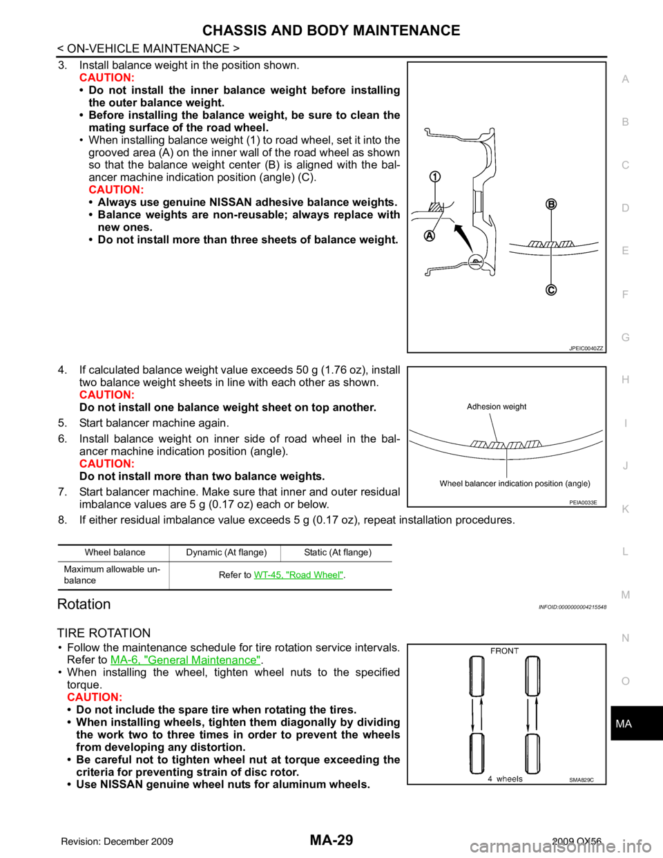
3. Install balance weight in the position shown.
CAUTION:
• Do not install the inner bala nce weight before installing
the outer balance weight.
• Before installing the balance weight, be sure to clean the mating surface of the road wheel.
• When installing balance weight (1) to road wheel, set it into the grooved area (A) on the inner wall of the road wheel as shown
so that the balance weight cent er (B) is aligned with the bal-
ancer machine indication position (angle) (C).
CAUTION:
• Always use genuine NISSAN adhesive balance weights.
• Balance weights are non-re usable; always replace with
new ones.
• Do not install more than th ree sheets of balance weight.
4. If calculated balance weight value exceeds 50 g (1.76 oz), install two balance weight sheets in line with each other as shown.
CAUTION:
Do not install one balance weight sheet on top another.
5. Start balancer machine again.
6. Install balance weight on inner side of road wheel in the bal- ancer machine indication position (angle).
CAUTION:
Do not install more than two balance weights.
7. Start balancer machine. Make sure that inner and outer residual imbalance values are 5 g (0.17 oz) each or below.
8. If either residual imbalance value exceeds 5 g (0.17 oz), repeat installation procedures.
RotationINFOID:0000000004215548
TIRE ROTATION
• Follow the maintenance schedule for tire rotation service intervals.
Refer to MA-6, "
General Maintenance".
• When installing the wheel, tighten wheel nuts to the specified
torque.
CAUTION:
• Do not include the spare tire when rotating the tires.
• When installing wheels, tighte n them diagonally by dividing
the work two to three times in order to prevent the wheels
from developing any distortion.
• Be careful not to tighten wh eel nut at torque exceeding the
criteria for preventing strain of disc rotor.
• Use NISSAN genuine wheel nuts for aluminum wheels.
JPEIC0040ZZ
Wheel balance Dynamic (At flange) Static (At flange)
Maximum allowable un-
balance Refer to WT-45, "
Road Wheel".
PEIA0033E
SMA829C
Revision: December 20092009 QX56
Page 2703 of 4171
MA-30
< ON-VEHICLE MAINTENANCE >
CHASSIS AND BODY MAINTENANCE
Checking Brake Fluid Level and Leaks
INFOID:0000000003777006
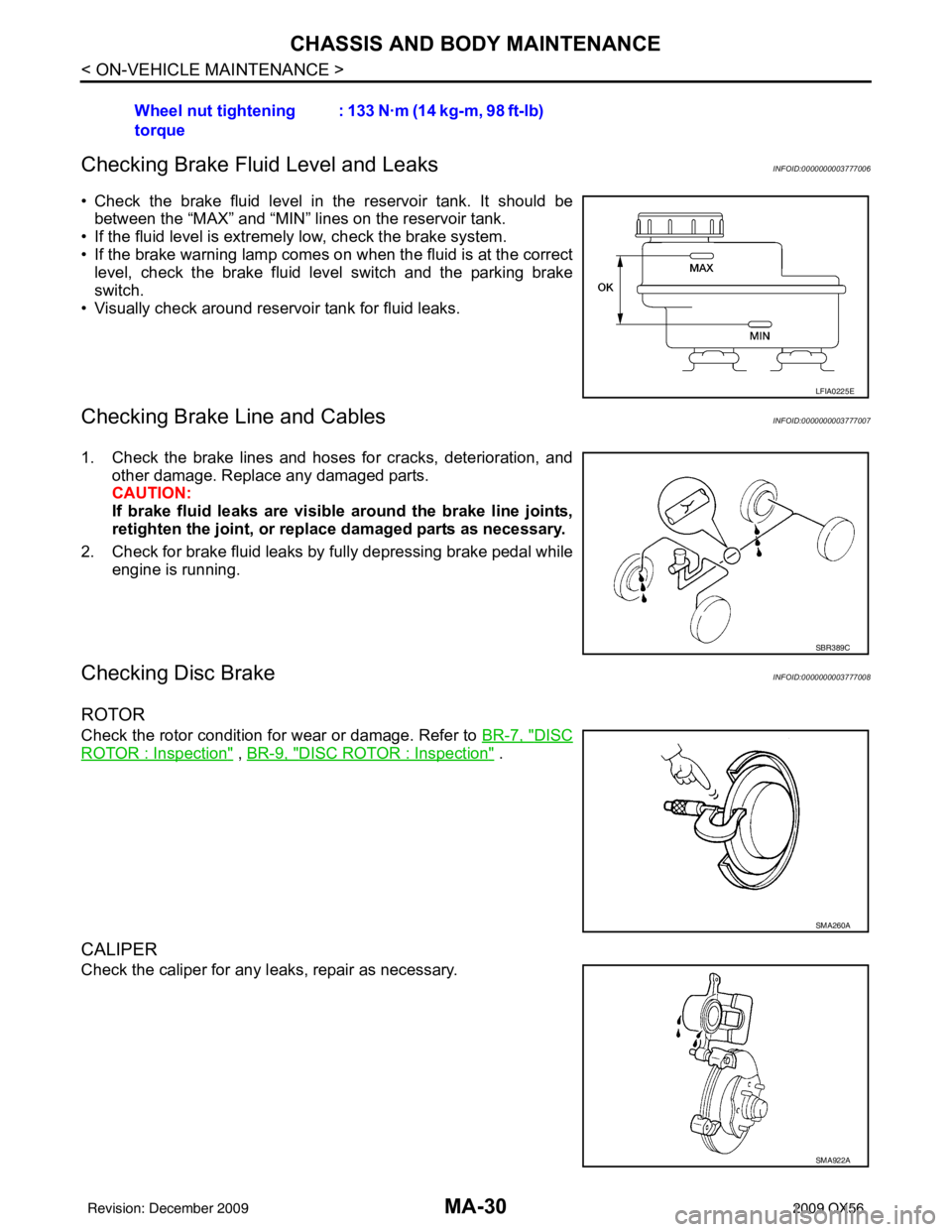
• Check the brake fluid level in the reservoir tank. It should be between the “MAX” and “MIN” lines on the reservoir tank.
• If the fluid level is extremely low, check the brake system.
• If the brake warning lamp comes on when the fluid is at the correct level, check the brake fluid level switch and the parking brake
switch.
• Visually check around reservoir tank for fluid leaks.
Checking Brake Line and CablesINFOID:0000000003777007
1. Check the brake lines and hoses for cracks, deterioration, and other damage. Replace any damaged parts.
CAUTION:
If brake fluid leaks are visible around the brake line joints,
retighten the joint, or replace damaged parts as necessary.
2. Check for brake fluid leaks by fully depressing brake pedal while engine is running.
Checking Disc BrakeINFOID:0000000003777008
ROTOR
Check the rotor condition for wear or damage. Refer to BR-7, "DISC
ROTOR : Inspection" , BR-9, "DISC ROTOR : Inspection" .
CALIPER
Check the caliper for any l eaks, repair as necessary.
Wheel nut tightening
torque
: 133 N·m (14 kg-m, 98 ft-lb)
LFIA0225E
SBR389C
SMA260A
SMA922A
Revision: December 20092009 QX56