2009 INFINITI QX56 brakes
[x] Cancel search: brakesPage 3080 of 4171

NOISE, VIBRATION AND HARSHNESS (NVH) TROUBLESHOOTINGRAX-5
< SYMPTOM DIAGNOSIS >
CEF
G H
I
J
K L
M A
B
RAX
N
O P
SYMPTOM DIAGNOSIS
NOISE, VIBRATION AND HARSHN ESS (NVH) TROUBLESHOOTING
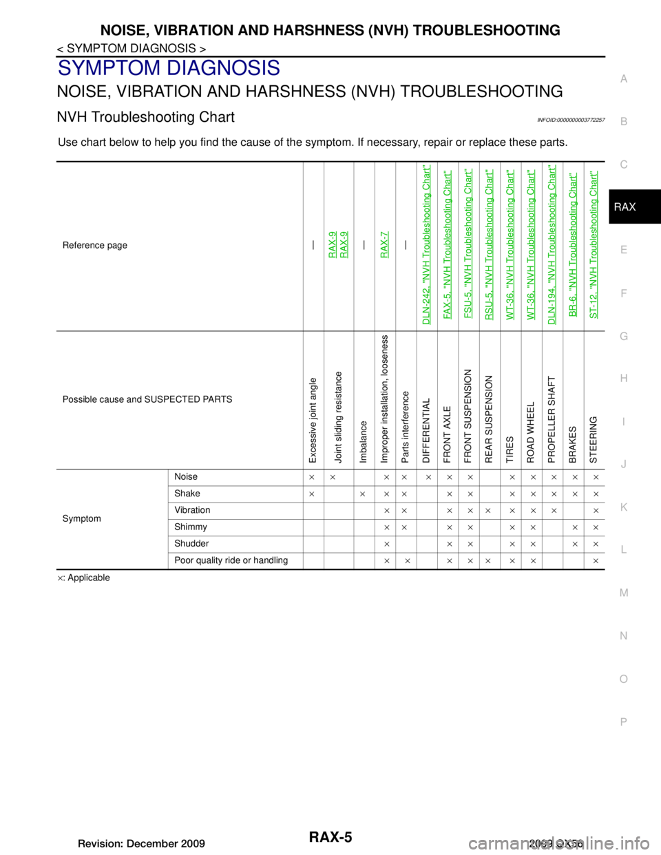
NVH Troubleshooting ChartINFOID:0000000003772257
Use chart below to help you find the cause of the symp tom. If necessary, repair or replace these parts.
×: Applicable
Reference page
—
RAX-9RAX-9—
RAX-7—
DLN-242, "NVH Troubleshooting Chart"
FAX-5, "NVH Troubleshooting Chart" FSU-5, "NVH Troubleshooting Chart"RSU-5, "NVH Troubleshooting Chart"WT-36, "NVH Troubleshooting Chart"WT-36, "NVH Troubleshooting Chart"DLN-194, "NVH Troubleshooting Chart"BR-6, "NVH Troubleshooting Chart"ST-12, "NVH Troubleshooting Chart"
Possible cause and SUSPECTED PARTS
Excessive joint angle
Joint sliding resistance
Imbalance
Improper installation, looseness
Parts interference
DIFFERENTIAL
FRONT AXLE
FRONT SUSPENSION
REAR SUSPENSION
TIRES
ROAD WHEEL
PROPELLER SHAFT
BRAKES
STEERING
Symptom Noise
×× ×× ××× ×××××
Shake × × ×× ×× ×××××
Vibration ×× ××× ××× ×
Shimmy ×× ×× ×× ××
Shudder × ××××××
Poor quality ride or handling ×× ××× ×× ×
Revision: December 20092009 QX56
Page 3134 of 4171

SQUEAK AND RATTLE TROUBLE DIAGNOSESRF-43
< SYMPTOM DIAGNOSIS >
C
DE
F
G H
I
J
L
M A
B
RF
N
O P
If the noise can be duplicated easily during the test drive, to help identify the source of the noise, try to dupli-
cate the noise with the vehicle stopped by doing one or all of the following:
1) Close a door.
2) Tap or push/pull around the area where the noise appears to be coming from.
3) Rev the engine.
4) Use a floor jack to recreate vehicle “twist”.
5) At idle, apply engine load. With brakes appllied, place A/T shift selector in drive position.
6) Raise the vehicle on a hoist and hit a tire with a rubber hammer.
• Drive the vehicle and attempt to duplicate the conditions the customer states exist when the noise occurs.
• If it is difficult to duplicate the noise, drive the vehicle slowly on an undulating or rough road to stress the
vehicle body.
CHECK RELATED SERVICE BULLETINS
After verifying the customer concern or symptom, check ASIST for Technical Service Bulletins (TSBs) related
to that concern or symptom.
If a TSB relates to the symptom, follow the procedure to repair the noise.
LOCATE THE NOISE AND IDENTIFY THE ROOT CAUSE
1. Narrow down the noise to a general area. To help pinpoint the source of the noise, use a listening tool (Chassis Ear: J-39570, Engine Ear and mechanics stethoscope).
2. Narrow down the noise to a more specific area and identify the cause of the noise by:
• removing the components in the area that you suspect the noise is coming from. Do not use too much force when removing clips and fasteners, otherwise clips and fastener can be broken
or lost during the repair, resulting in the creation of new noise.
• tapping or pushing/pulling the component that you suspect is causing the noise.
Do not tap or push/pull the component with excessive force, otherwise the noise will be eliminated only tem-
porarily.
• feeling for a vibration with your hand by touching the component(s) that you suspect is (are) causing the
noise.
• placing a piece of paper between components that you suspect are causing the noise.
• looking for loose components and contact marks. Refer to RF-44, "
Generic Squeak and Rattle Troubleshooting".
REPAIR THE CAUSE
• If the cause is a loose component, tighten the component securely.
• If the cause is insufficient clearance between components:
- separate components by repositioning or loos ening and retightening the component, if possible.
- insulate components with a suitable insulator such as urethane pads, foam blocks, felt cloth tape or urethane tape. A Nissan Squeak and Rattle Kit (J-43980) is av ailable through your authorized Nissan Parts Depart-
ment.
CAUTION:
Do not use excessive force as many components are constructed of plastic and may be damaged.
NOTE:
Always check with the Parts Department for the latest parts information.
The following materials are contained in the Niss an Squeak and Rattle Kit (J-43980). Each item can be
ordered separately as needed.
URETHANE PADS [1.5 mm (0.059 in) thick]
Insulates connectors, harness, etc.
76268-9E005: 100 ×135 mm (3.94 ×5.31 in)/76884-71L01: 60 ×85 mm (2.36 ×3.35 in)/76884-
71L02: 15 ×25 mm (0.59 ×0.98 in)
INSULATOR (Foam blocks)
Insulates components from contact. Can be used to fill space behind a panel.
73982-9E000: 45 mm (1.77 in) thick, 50 ×50 mm (1.97 ×1.97 in)/73982-
50Y00: 10 mm (0.39 in) thick, 50 ×50 mm (1.97 ×1.97 in)
INSULATOR (Light foam block)
80845-71L00: 30 mm (1.18 in) thick, 30 ×50 mm (1.18 ×1.97 in)
FELT CLOTHTAPE
Used to insulate where movement does not occur. Ideal for instrument panel applications.
68370-4B000: 15 ×25 mm (0.59 ×0.98 in) pad/68239-13E00: 5 mm (0.20 in) wide tape roll
The following materials, not found in the kit, can also be used to repair squeaks and rattles.
UHMW (TEFLON) TAPE
Revision: December 20092009 QX56
Page 3153 of 4171

NOISE, VIBRATION AND HARSHNESS (NVH) TROUBLESHOOTINGRSU-5
< SYMPTOM DIAGNOSIS >
C
DF
G H
I
J
K L
M A
B
RSU
N
O P
SYMPTOM DIAGNOSIS
NOISE, VIBRATION AND HARSHN ESS (NVH) TROUBLESHOOTING
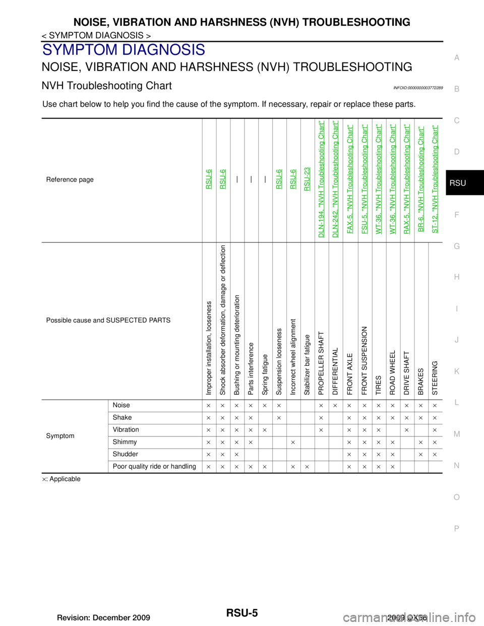
NVH Troubleshooting ChartINFOID:0000000003772289
Use chart below to help you find the cause of the symp tom. If necessary, repair or replace these parts.
×: ApplicableReference page
RSU-6RSU-6—
—
—
RSU-6RSU-6RSU-23
DLN-194, "NVH Troubleshooting Chart"DLN-242, "NVH Troubleshooting Chart"FAX-5, "NVH Troubleshooting Chart"FSU-5, "NVH Troubleshooting Chart"WT-36, "NVH Troubleshooting Chart"WT-36, "NVH Troubleshooting Chart"RAX-5, "NVH Troubleshooting Chart"BR-6, "NVH Troubleshooting Chart"ST-12, "NVH Troubleshooting Chart"
Possible cause and SUSPECTED PARTS
Improper installation, looseness
Shock absorber deformation, damage or deflection
Bushing or mounting deterioration
Parts interference
Spring fatigue
Suspension looseness
Incorrect wheel alignment
Stabilizer bar fatigue
PROPELLER SHAFT
DIFFERENTIAL
FRONT AXLE
FRONT SUSPENSION
TIRES
ROAD WHEEL
DRIVE SHAFT
BRAKES
STEERING
Symptom Noise
×××××× ××× ××××××
Shake ×××× × × × ××××××
Vibration ××××× × × ×× × ×
Shimmy ×××× × × ××× ××
Shudder ××× × ××× ××
Poor quality ride or handling ××××× ×× × ×××
Revision: December 20092009 QX56
Page 3191 of 4171

SEAT BELTSSB-13
< ON-VEHICLE REPAIR >
C
DE
F
G
I
J
K L
M A
B
SB
N
O P
2. Proceed to the designated safe area.
3. Drive the vehicle at approximately 16 km/h (10 MPH). Notify any passengers of a pending sudden stop. The driver and passenger must be prepared to brace t hemselves in the event the retractor does not lock.
Apply brakes firmly and make a very hard stop.
During stop, seat belts should lock and not be extended. If the seat belt retractor and belt assembly does not
lock, perform the retractor off-vehicle check.
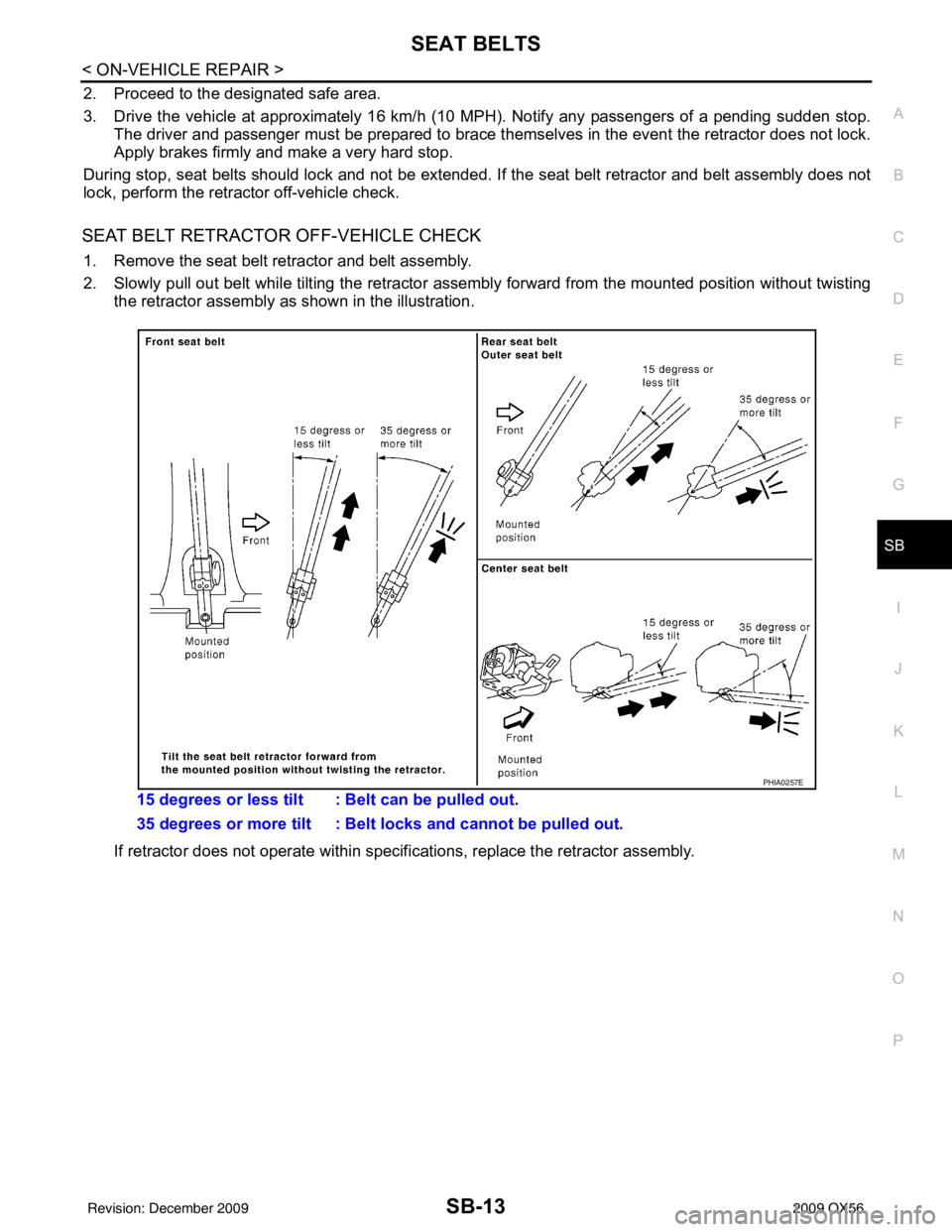
SEAT BELT RETRACTOR OFF-VEHICLE CHECK
1. Remove the seat belt retractor and belt assembly.
2. Slowly pull out belt while tilting the retractor assembly forward from the mounted position without twisting
the retractor assembly as shown in the illustration.
If retractor does not operate within specif ications, replace the retractor assembly.
15 degrees or less tilt : Belt can be pulled out.
35 degrees or more tilt : Belt locks and cannot be pulled out.
PHIA0257E
Revision: December 20092009 QX56
Page 3427 of 4171

SN
INSPECTION AND ADJUSTMENTSN-5
< BASIC INSPECTION >
C
DE
F
G H
I
J
K L
M B A
O P
INSPECTION AND ADJUSTMENT
Preliminary CheckINFOID:0000000003776738
DESCRIPTION
The purpose of the sonar sensor preliminary check is to confirm that there are no outside factors affecting the
sonar system.
CONDITIONS
• Ignition switch ON
• No obstructions within 3.0 m (10 ft.) of sonar sensors
SONAR SENSOR STATUS CHECK
• Check that the sonar sensors are properly aligned (no deformation in sensor mounting areas).
• Check that snow, mud or other foreign obj ects are not adhering to the sonar sensors.
• Check that there is no deformation, scratc hes or other damage to the sonar sensors.
• Check that water has not accu mulated in the sonar sensors.
CAUTION:
Use water, cotton swab, or other soft material for cleaning the sensors.
1. Check that there are no obstacles wit hin each sonar sensor's detection range.
2. Check that there are no nearby ultrasound sources such as the sounds of vehicle horns, motorcycle
engines or truck air brakes.
3. Check that the vehicle is on a level surface.
Sonar sensors Detection range
Front Approx. 1.0 m (3 ft.) maximum
Rear Approx. 1.8 m (5.9 ft.) maximum
Revision: December 20092009 QX56
Page 3603 of 4171

ST-12
< SYMPTOM DIAGNOSIS >
NOISE, VIBRATION AND HARSHNESS (NVH) TROUBLESHOOTING
SYMPTOM DIAGNOSIS
NOISE, VIBRATION AND HARSHNESS (NVH) TROUBLESHOOTING
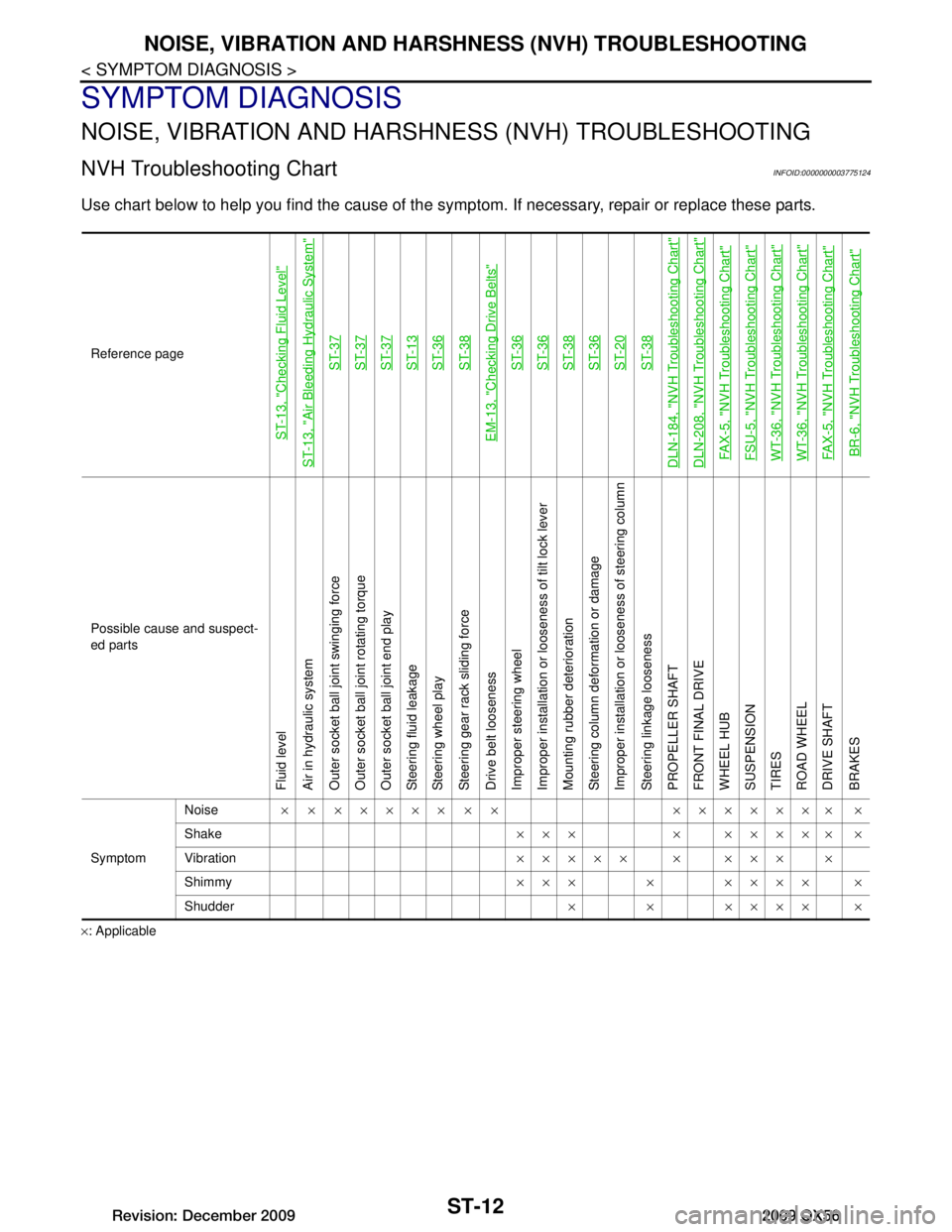
NVH Troubleshooting ChartINFOID:0000000003775124
Use chart below to help you find the cause of the symp tom. If necessary, repair or replace these parts.
×: ApplicableReference page
ST-13, "Checking Fluid Level"
ST-13, "Air Bleeding Hydraulic System"
ST-37ST-37ST-37ST-13ST-36ST-38
EM-13, "Checking Drive Belts"
ST-36ST-36ST-38ST-36ST-20ST-38
DLN-184, "NVH Troubleshooting Chart"DLN-208, "NVH Troubleshooting Chart"FAX-5, "NVH Troubleshooting Chart"FSU-5, "NVH Troubleshooting Chart"WT-36, "NVH Troubleshooting Chart"WT-36, "NVH Troubleshooting Chart"FAX-5, "NVH Troubleshooting Chart"BR-6, "NVH Troubleshooting Chart"
Possible cause and suspect-
ed parts
Fluid level
Air in hydraulic system
Outer socket ball joint swinging force
Outer socket ball joint rotating torque
Outer socket ball joint end play
Steering fluid leakage
Steering wheel play
Steering gear rack sliding force
Drive belt looseness
Improper steering wheel
Improper installation or looseness of tilt lock lever
Mounting rubber deterioration
Steering column deformation or damage
Improper installation or looseness of steering column
Steering linkage looseness
PROPELLER SHAFT
FRONT FINAL DRIVE
WHEEL HUB
SUSPENSION
TIRES
ROAD WHEEL
DRIVE SHAFT
BRAKES
Symptom
Noise
× × ××××× × × ××××××× ×
Shake ××× × ××××× ×
Vibration ××××× × ××× ×
Shimmy ××× × ×××× ×
Shudder × × ×××× ×
Revision: December 20092009 QX56
Page 3655 of 4171

DIAGNOSIS AND REPAIR WORKFLOWTM-7
< BASIC INSPECTION >
CEF
G H
I
J
K L
M A
B
TM
N
O P
DIAGNOSTIC WORK SHEET
Symptoms �† Vehicle does not move. ( �† Any position �† Particular position)
�† No up-shift ( �† 1st → 2nd �† 2nd → 3rd �† 3rd → 4th �† 4th → 5th)
�† No down-shift ( �† 5th → 4th �† 4th → 3rd �† 3rd → 2nd �† 2nd → 1st)
�† Lock-up malfunction
�† Shift point too high or too low.
�† Shift shock or slip ( �† N → D �† N → R �† Lock-up �† Any drive position)
�† Noise or vibration
�† No kick down
�† No pattern select
�† Others
()
A/T CHECK indicator lamp �† Continuously lit �† Not lit
Malfunction indicator lamp (MIL) �† Continuously lit �† Not lit
1 �†
Read the item on cautions concerning fail-safe and understand the customer's com-
plaint. TM-115
2�†
A/T fluid inspection, stall test and line pressure test
�† A/T fluid inspection
TM-179
�† Leak (Repair leak location.)
�† Sta te
�† Amount
�† Stall test
TM-186
�† Torque converter one-way clutch
�† Front brake
�† High and low reverse clutch
�† Low coast brake
�† Forward brake
�† Reverse brake
�† Forward one-way clutch �†
1st one-way
clutch
�† 3rd one-way
clutch
�† Engine
�† Line pressure low
�† Except for input
clutch and direct
clutch, clutches and
brakes OK
�† Line pressure test - Suspected part: TM-188
3�†
Perform self-diagnosis. — Check detected items to repair or replace malfunctioning
part. TM-32
4�†
Perform road test.
5-1 �† Check before engine is started TM-190
5-2�† Check at idle TM-190
5-3 Cruise test�†
Part 1 TM-191�† Part 2 TM-193
�† Part 3 TM-194
�† Check malfunction phenomena to repair or replace malfunctioning part after completing all road test.
Refer to TM-152, "Symptom Table"
.
5 �† Drive vehicle to check that the malfunction phenomenon has been resolved.
6 �† Erase the results of the self-diagnosis from the TCM and the ECM. TM-30
Revision: December 20092009 QX56