2009 INFINITI QX56 wheel
[x] Cancel search: wheelPage 2132 of 4171
EXT-26
< SERVICE INFORMATION >
REAR SPOILER
REAR SPOILER
Removal and InstallationINFOID:0000000003776113
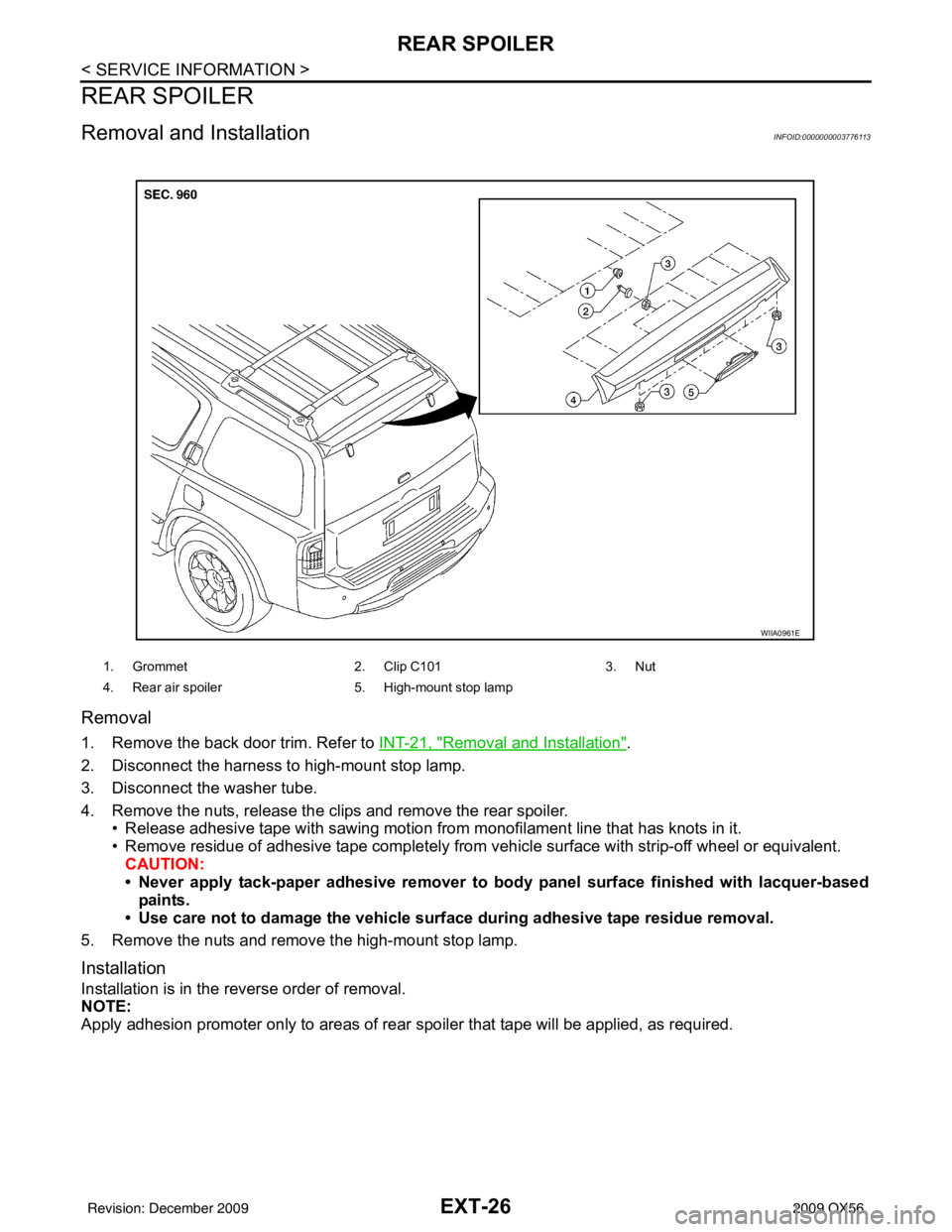
Removal
1. Remove the back door trim. Refer to INT-21, "Removal and Installation".
2. Disconnect the harness to high-mount stop lamp.
3. Disconnect the washer tube.
4. Remove the nuts, release the clips and remove the rear spoiler. • Release adhesive tape with sawing motion from monofilament line that has knots in it.
• Remove residue of adhesive tape completely from v ehicle surface with strip-off wheel or equivalent.
CAUTION:
• Never apply tack-paper adhesive remover to bo dy panel surface finished with lacquer-based
paints.
• Use care not to damage the vehicle surf ace during adhesive tape residue removal.
5. Remove the nuts and remove the high-mount stop lamp.
Installation
Installation is in the reverse order of removal.
NOTE:
Apply adhesion promoter only to areas of rear spoiler that tape will be applied, as required.
1. Grommet2. Clip C1013. Nut
4. Rear air spoiler 5. High-mount stop lamp
WIIA0961E
Revision: December 20092009 QX56
Page 2138 of 4171
FAX-1
TRANSMISSION & DRIVELINE
CEF
G H
I
J
K L
M
SECTION FA X
A
B
FA X
N
O P
CONTENTS
FRONT AXLE
PRECAUTION ................ ...............................2
PRECAUTIONS .............................................. .....2
Precaution for Supplemental Restraint System
(SRS) "AIR BAG" and "SEAT BELT PRE-TEN-
SIONER" ............................................................. ......
2
Precaution Necessary for Steering Wheel Rota-
tion After Battery Disconnect .....................................
2
Precaution .................................................................3
PREPARATION ............................................4
PREPARATION .............................................. .....4
Special Service Tool ........................................... ......4
Commercial Service Tool ..........................................4
SYMPTOM DIAGNOSIS ...............................5
NOISE, VIBRATION AND HARSHNESS
(NVH) TROUBLESHOOTING ........................ .....
5
NVH Troubleshooting Chart ................................ ......5
ON-VEHICLE MAINTENANCE .....................6
WHEEL HUB ......................................................6
On-Vehicle Inspection and Service ..................... .....6
REMOVAL AND INSTALLATION ................7
WHEEL HUB ......................................................7
Removal and Installation ..................................... .....7
DRIVE SHAFT ....................................................9
Removal and Installation ..........................................9
DISASSEMBLY AND ASSEMBLY ..............11
DRIVE SHAFT ...................................................11
Disassembly and Assembly ................................. ....11
SERVICE DATA AND SPECIFICATIONS
(SDS) ............... .............................................
16
SERVICE DATA AND SPECIFICATIONS
(SDS) .................................................................
16
Wheel Bearing ..................................................... ....16
Drive Shaft ...............................................................16
Boot Bands ..............................................................16
Revision: December 20092009 QX56
Page 2139 of 4171
FAX-2
< PRECAUTION >
PRECAUTIONS
PRECAUTION
PRECAUTIONS
Precaution for Supplemental Restraint System (SRS) "AIR BAG" and "SEAT BELT
PRE-TENSIONER"
INFOID:0000000005867499
The Supplemental Restraint System such as “A IR BAG” and “SEAT BELT PRE-TENSIONER”, used along
with a front seat belt, helps to reduce the risk or severi ty of injury to the driver and front passenger for certain
types of collision. This system includes seat belt switch inputs and dual stage front air bag modules. The SRS
system uses the seat belt switches to determine the front air bag deployment, and may only deploy one front
air bag, depending on the severity of a collision and w hether the front occupants are belted or unbelted.
Information necessary to service the system safely is included in the SR and SB section of this Service Man-
ual.
WARNING:
• To avoid rendering the SRS inopera tive, which could increase the risk of personal injury or death in
the event of a collision which would result in air bag inflation, all maintenance must be performed by
an authorized NISS AN/INFINITI dealer.
Improper maintenance, including in correct removal and installation of the SRS, can lead to personal
injury caused by unintent ional activation of the system. For re moval of Spiral Cable and Air Bag
Module, see the SR section.
Do not use electrical test equipmen t on any circuit related to the SRS unless instructed to in this
Service Manual. SRS wiring harnesses can be identi fied by yellow and/or orange harnesses or har-
ness connectors.
PRECAUTIONS WHEN USING POWER TOOLS (AIR OR ELECTRIC) AND HAMMERS
WARNING:
When working near the Airbag Diagnosis Sensor Unit or other Airbag System sensors with the Igni-
tion ON or engine running, DO NOT use air or electri c power tools or strike near the sensor(s) with a
hammer. Heavy vibration could activate the sensor( s) and deploy the air bag(s), possibly causing
serious injury.
When using air or electric power tools or hammers , always switch the Ignition OFF, disconnect the
battery, and wait at least 3 minu tes before performing any service.
Precaution Necessary for Steering W heel Rotation After Battery Disconnect
INFOID:0000000005867500
NOTE:
This Procedure is applied only to models with Intelli gent Key system and NATS (NISSAN ANTI-THEFT SYS-
TEM).
Remove and install all control units after disconnecting both battery cables with the ignition knob in the
″LOCK ″ position.
Always use CONSULT-III to perform self-diagnosis as a part of each function inspection after finishing work.
If DTC is detected, perform trouble diagnosis according to self-diagnostic results.
For models equipped with the Intelligent Key system and NATS, an electrically controlled steering lock mech-
anism is adopted on the key cylinder.
For this reason, if the battery is disconnected or if the battery is discharged, the steering wheel will lock and
steering wheel rotation will become impossible.
If steering wheel rotation is required when battery pow er is interrupted, follow the procedure below before
starting the repair operation.
OPERATION PROCEDURE
1. Connect both battery cables. NOTE:
Supply power using jumper cables if battery is discharged.
2. Use the Intelligent Key or mechanical key to turn the ignition switch to the ″ACC ″ position. At this time, the
steering lock will be released.
3. Disconnect both battery cables. The steering lock will remain released and the steering wheel can be
rotated.
4. Perform the necessary repair operation.
Revision: December 20092009 QX56
Page 2140 of 4171
PRECAUTIONSFAX-3
< PRECAUTION >
CEF
G H
I
J
K L
M A
B
FA X
N
O P
5. When the repair work is completed, return the ignition switch to the ″LOCK ″ position before connecting
the battery cables. (At this time, the steering lock mechanism will engage.)
6. Perform a self-diagnosis check of al l control units using CONSULT-III.
PrecautionINFOID:0000000003772244
Observe the following precautions when disassembling and servicing the wheel hub and drive shafts.
Perform work in a location which is as dust-free as possible.
Before disassembling and servicing, clean the outside of parts.
Prevention of the entry of foreign objects must be taken into account during disassembly of the component
parts.
Disassembled parts must be carefully reassembled in t he correct order. If work is interrupted, a clean cover
must be placed over parts.
Paper shop cloths must be used. Fabric shop cloths must not be used because of the danger of lint adhering
to parts.
Disassembled parts (except for rubber parts) should be cleaned with a suitable solvent which shall be removed by blowing with air or wiping with paper shop cloths.
Revision: December 20092009 QX56
Page 2142 of 4171
NOISE, VIBRATION AND HARSHNESS (NVH) TROUBLESHOOTINGFAX-5
< SYMPTOM DIAGNOSIS >
CEF
G H
I
J
K L
M A
B
FA X
N
O P
SYMPTOM DIAGNOSIS
NOISE, VIBRATION AND HARSHN ESS (NVH) TROUBLESHOOTING
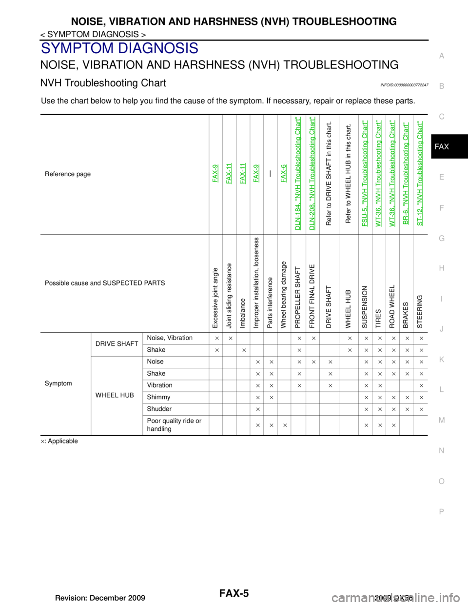
NVH Troubleshooting ChartINFOID:0000000003772247
Use the chart below to help you find t he cause of the symptom. If necessary, repair or replace these parts.
×: ApplicableReference page
FA X - 9FA X - 11FA X - 11FA X - 9—
FA X - 6
DLN-184, "NVH Troubleshooting Chart"DLN-208, "NVH Troubleshooting Chart"Refer to DRIVE SHAFT in this chart.
Refer to WHEEL HUB in this chart.
FSU-5, "NVH Troubleshooting Chart"WT-36, "NVH Troubleshooting Chart"WT-36, "NVH Troubleshooting Chart"BR-6, "NVH Troubleshooting Chart"ST-12, "NVH Troubleshooting Chart"
Possible cause and SUSPECTED PARTS
Excessive joint angle
Joint sliding resistance
Imbalance
Improper installation, looseness
Parts interference
Wheel bearing damage
PROPELLER SHAFT
FRONT FINAL DRIVE
DRIVE SHAFT
WHEEL HUB
SUSPENSION
TIRES
ROAD WHEEL
BRAKES
STEERING
Symptom DRIVE SHAFT
Noise, Vibration
×× × × × ×××× ×
Shake × × × × ×××× ×
WHEEL HUB Noise
×× × × × ×××× ×
Shake ×× × × ×××× ×
Vibration ×× × × ×× ×
Shimmy ×× ×××× ×
Shudder ××××××
Poor quality ride or
handling ××× ×××
Revision: December 20092009 QX56
Page 2143 of 4171
FAX-6
< ON-VEHICLE MAINTENANCE >
WHEEL HUB
ON-VEHICLE MAINTENANCE
WHEEL HUB
On-Vehicle Inspection and ServiceINFOID:0000000003772248
Make sure the mounting conditions (looseness, backlash) of each component and component status (wear,
damage) are normal.
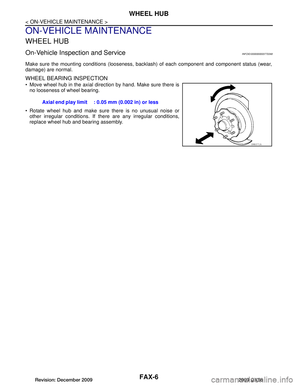
WHEEL BEARING INSPECTION
Move wheel hub in the axial direction by hand. Make sure there is
no looseness of wheel bearing.
Rotate wheel hub and make sure there is no unusual noise or other irregular conditions. If there are any irregular conditions,
replace wheel hub and bearing assembly. Axial end play limit : 0.05 mm (0.002 in) or less
SMA571A
Revision: December 20092009 QX56
Page 2144 of 4171
WHEEL HUBFAX-7
< REMOVAL AND INSTALLATION >
CEF
G H
I
J
K L
M A
B
FA X
N
O P
REMOVAL AND INSTALLATION
WHEEL HUB
Removal and InstallationINFOID:0000000005889823
REMOVAL
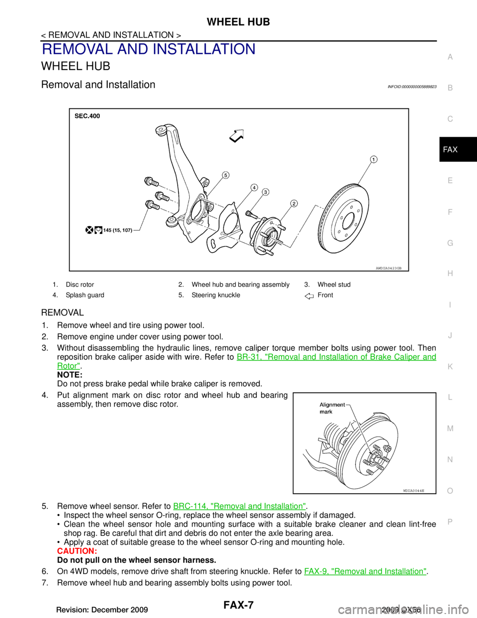
1. Remove wheel and tire using power tool.
2. Remove engine under cover using power tool.
3. Without disassembling the hydraulic lines, remove caliper torque member bolts using power tool. Then reposition brake caliper aside with wire. Refer to BR-31, "Removal and Installation of Brake Caliper and
Rotor".
NOTE:
Do not press brake pedal while brake caliper is removed.
4. Put alignment mark on disc rotor and wheel hub and bearing assembly, then remove disc rotor.
5. Remove wheel sensor. Refer to BRC-114, "Removal and Installation"
.
Inspect the wheel sensor O-ring, replac e the wheel sensor assembly if damaged.
Clean the wheel sensor hole and mounting surface with a suitable brake cleaner and clean lint-free shop rag. Be careful that dirt and debr is do not enter the axle bearing area.
Apply a coat of suitable grease to t he wheel sensor O-ring and mounting hole.
CAUTION:
Do not pull on th e wheel sensor harness.
6. On 4WD models, remove drive shaft from steering knuckle. Refer to FAX-9, "Removal and Installation"
.
7. Remove wheel hub and bearing assembly bolts using power tool.
1. Disc rotor 2. Wheel hub and bearing assembly 3. Wheel stud
4. Splash guard 5. Steering knuckle Front
AWDIA0423GB
WDIA0044E
Revision: December 20092009 QX56
Page 2145 of 4171
FAX-8
< REMOVAL AND INSTALLATION >
WHEEL HUB
8. Remove splash guard and wheel hub and bearing assembly from steering knuckle.
INSPECTION AFTER REMOVAL
Check for deformity, cracks and damage on each part, replace if necessary.
INSTALLATION
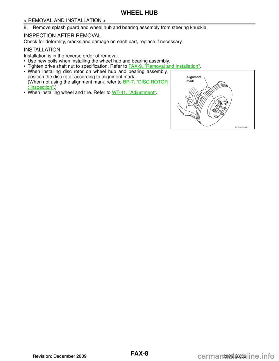
Installation is in the reverse order of removal.
Use new bolts when installing the wheel hub and bearing assembly.
Tighten drive shaft nut to specification. Refer to FAX-9, "Removal and Installation"
.
When installing disc rotor on wheel hub and bearing assembly, position the disc rotor according to alignment mark.
(When not using the alignment mark, refer to BR-7, "DISC ROTOR
: Inspection".)
When installing wheel and tire. Refer to WT-41, "Adjustment"
.
WDIA0044E
Revision: December 20092009 QX56