2009 INFINITI QX56 relay
[x] Cancel search: relayPage 2944 of 4171
PG
FUSE, FUSIBLE LINK AND RELAY BOXPG-73
< COMPONENT DIAGNOSIS >
C
DE
F
G H
I
J
K L
B A
O P
N
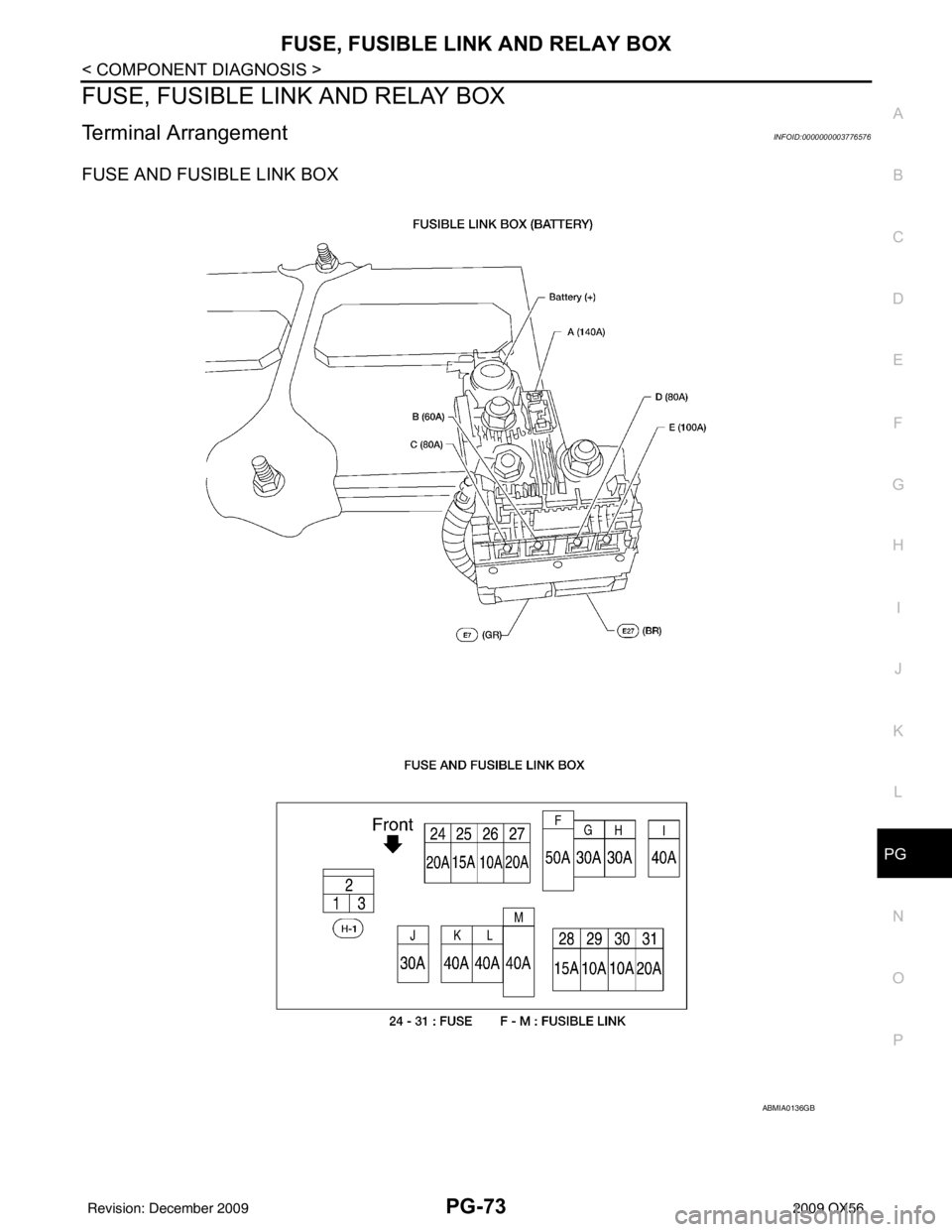
FUSE, FUSIBLE LINK AND RELAY BOX
Terminal ArrangementINFOID:0000000003776576
FUSE AND FUSIBLE LINK BOX
ABMIA0136GB
Revision: December 20092009 QX56
Page 2945 of 4171
PG-74
< COMPONENT DIAGNOSIS >
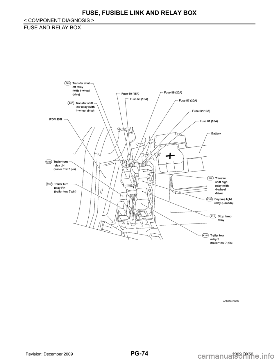
FUSE, FUSIBLE LINK AND RELAY BOX
FUSE AND RELAY BOX
ABMIA0166GB
Revision: December 20092009 QX56
Page 2950 of 4171

PWC-2
PASSENGER SIDE : Description ...........................25
PASSENGER SIDE : Compo nent Function Check
...
25
PASSENGER SIDE : Diagnosis Procedure ........ ...25
REAR LH ................................................................ ...28
REAR LH : Description ...........................................28
REAR LH : Component Function Check ................28
REAR LH : Diagnosis Procedure ............................28
REAR RH ............................................................... ...30
REAR RH : Description ..........................................31
REAR RH : Component Function Check ................31
REAR RH : Diagnosis Procedure ...........................31
DOOR SWITCH .................................................34
Description ........................................................... ...34
Component Function Check ...................................34
Diagnosis Procedure ..............................................34
Component Inspection ............................................35
DOOR KEY CYLINDER SWITCH ......................36
Description ........................................................... ...36
Component Function Check ...................................36
Diagnosis Procedure ..............................................36
Component Inspection ............................................37
POWER WINDOW SERIAL LINK .....................39
POWER WINDOW MAIN SWITCH ........................ ...39
POWER WINDOW MAIN SWITCH : Description ...39
POWER WINDOW MAIN SWITCH : Component
Function Check .......................................................
39
POWER WINDOW MAIN SWITCH : Diagnosis
Procedure ...............................................................
39
FRONT POWER WINDOW SWITCH ..................... ...40
FRONT POWER WINDOW SWITCH : Descrip-
tion ..........................................................................
40
FRONT POWER WINDOW SWITCH : Compo-
nent Function Check ...............................................
40
FRONT POWER WINDOW SWITCH : Diagnosis
Procedure ...............................................................
41
REAR POWER WINDOW SWITCH ....................... ...42
REAR POWER WINDOW SWITCH : Power Win-
dow Serial Link Check Rear LH or RH ...................
42
POWER WINDOW LOCK SWITCH ...................43
Description ........................................................... ...43
Component Function Check ...................................43
REAR POWER VENT WINDOW SWITCH
CIRCUIT CHECK ...............................................
44
Description ........................................................... ...44
Diagnosis Procedure - (Early Production) ..............44
Diagnosis Procedure - (Late Production) ...............44
REAR POWER VENT WINDOW MOTOR LH
CIRCUIT CHECK ...............................................
46
Description ........................................................... ...46
Diagnosis Procedure ..............................................46
REAR POWER VENT WINDOW MOTOR RH
CIRCUIT CHECK ...............................................
47
Description ........................................................... ...47
Diagnosis Procedure ...............................................47
REAR POWER VENT WINDOW RELAY
(OPEN) CHECK .................................................
48
Description ........................................................... ...48
Diagnosis Procedure - (Early Production) ...............48
Diagnosis Procedure - (Late Production) ............. ...49
REAR POWER VENT WINDOW RELAY
(CLOSE) CHECK ...............................................
51
Description ........................................................... ...51
Diagnosis Procedure - (Early Production) ...............51
Diagnosis Procedure - (Late Production) ............. ...52
ECU DIAGNOSIS .......................................54
BCM (BODY CONTROL MODULE) ............... ...54
Reference Value .................................................. ...54
Terminal Layout ......................................................56
Physical Values .......................................................56
Wiring Diagram .......................................................62
POWER WINDOW MAIN SWITCH ...................67
Reference Value .................................................. ...67
Wiring Diagram .......................................................69
Fail Safe .................................................................80
FRONT POWER WINDOW SWITCH ................82
Reference Value .................................................. ...82
Wiring Diagram .......................................................84
Fail Safe .................................................................95
SYMPTOM DIAGNOSIS ............................97
NONE OF THE POWER WINDOWS CAN BE
OPERATED USING ANY SWITCH ................ ...
97
Diagnosis Procedure ............................................ ...97
DRIVER SIDE POWER WINDOW ALONE
DOES NOT OPERATE ......................................
98
Diagnosis Procedure ............................................ ...98
FRONT PASSENGER SIDE POWER WIN-
DOW ALONE DOES NOT OPERATE ...............
99
Diagnosis Procedure ............................................ ...99
REAR LH SIDE POWER WINDOW ALONE
DOES NOT OPERATE .....................................
100
Diagnosis Procedure ............................................ .100
REAR RH SIDE POWER WINDOW ALONE
DOES NOT OPERATE .....................................
101
Diagnosis Procedure ............................................ .101
ANTI-PINCH SYSTEM DOES NOT OPERATE
NORMALLY (DRIVER SIDE) ...........................
102
Diagnosis Procedure ............................................ .102
Revision: December 20092009 QX56
Page 2956 of 4171
PWC-8
< FUNCTION DIAGNOSIS >
POWER WINDOW SYSTEM
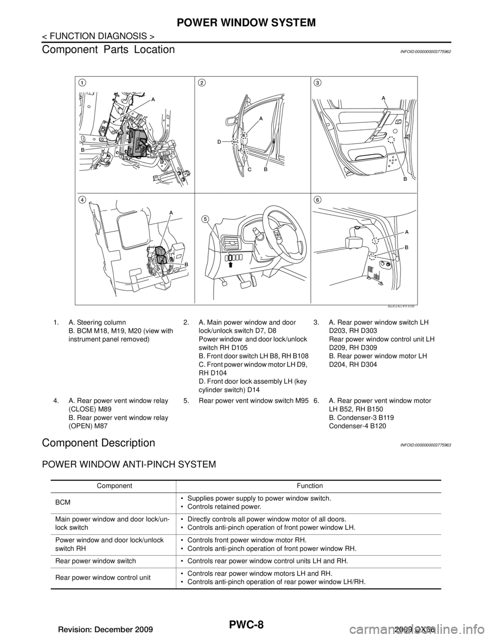
Component Parts Location
INFOID:0000000003775962
Component DescriptionINFOID:0000000003775963
POWER WINDOW ANTI-PINCH SYSTEM
ALKIA1893GB
1. A. Steering column B. BCM M18, M19, M20 (view with
instrument panel removed) 2. A. Main power window and door
lock/unlock switch D7, D8
Power window and door lock/unlock
switch RH D105
B. Front door switch LH B8, RH B108
C. Front power win dow motor LH D9,
RH D104
D. Front door lock assembly LH (key
cylinder switch) D14 3. A. Rear power window switch LH
D203, RH D303
Rear power window control unit LH
D209, RH D309
B. Rear power window motor LH
D204, RH D304
4. A. Rear power vent window relay (CLOSE) M89
B. Rear power ve nt window relay
(OPEN) M87 5. Rear power vent window switch M95 6. A. Rear power vent window motor
LH B52, RH B150
B. Condenser-3 B119
Condenser-4 B120
Component Function
BCM Supplies power supply to power window switch.
Controls retained power.
Main power window and door lock/un-
lock switch Directly controls all power window motor of all doors.
Controls anti-pinch operation of front power window LH.
Power window and door lock/unlock
switch RH Controls front power window motor RH.
Controls anti-pinch operation of front power window RH.
Rear power window switch Controls rear power window control units LH and RH.
Rear power window control unit Controls rear power window motors LH and RH.
Controls anti-pinch operation of rear power window LH/RH.
Revision: December 20092009 QX56
Page 2994 of 4171
PWC-46
< COMPONENT DIAGNOSIS >
REAR POWER VENT WINDOW MOTOR LH CIRCUIT CHECK
REAR POWER VENT WINDOW MOTOR LH CIRCUIT CHECK
DescriptionINFOID:0000000005864660
Rear power vent windows OPEN/CLOSE by receiving t he signal from rear power vent window relays which
are controlled by the rear power vent window switch.
Diagnosis ProcedureINFOID:0000000005864661
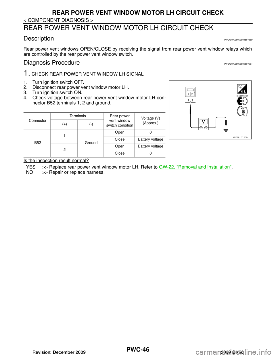
1. CHECK REAR POWER VENT WINDOW LH SIGNAL
1. Turn ignition switch OFF.
2. Disconnect rear power vent window motor LH.
3. Turn ignition switch ON.
4. Check voltage between rear power vent window motor LH con- nector B52 terminals 1, 2 and ground.
Is the inspection result normal?
YES >> Replace rear power vent window motor LH. Refer to GW-22, "Removal and Installation".
NO >> Repair or replace harness.
Connector Terminals Rear power
vent window
switch condition Voltage (V)
(Approx.)
(+) (-)
B52 1
Ground Open 0
Close Battery voltage
2 Open Battery voltage
Close 0
ALKIA1037GB
Revision: December 20092009 QX56
Page 2995 of 4171
REAR POWER VENT WINDOW MOTOR RH CIRCUIT CHECK
PWC-47
< COMPONENT DIAGNOSIS >
C
D E
F
G H
I
J
L
M A
B
PWC
N
O P
REAR POWER VENT WINDOW MOTOR RH CIRCUIT CHECK
DescriptionINFOID:0000000005864662
Rear power vent windows OPEN/CLOSE by receiving t he signal from rear power vent window relays which
are controlled by the rear power vent window switch.
Diagnosis ProcedureINFOID:0000000005864663
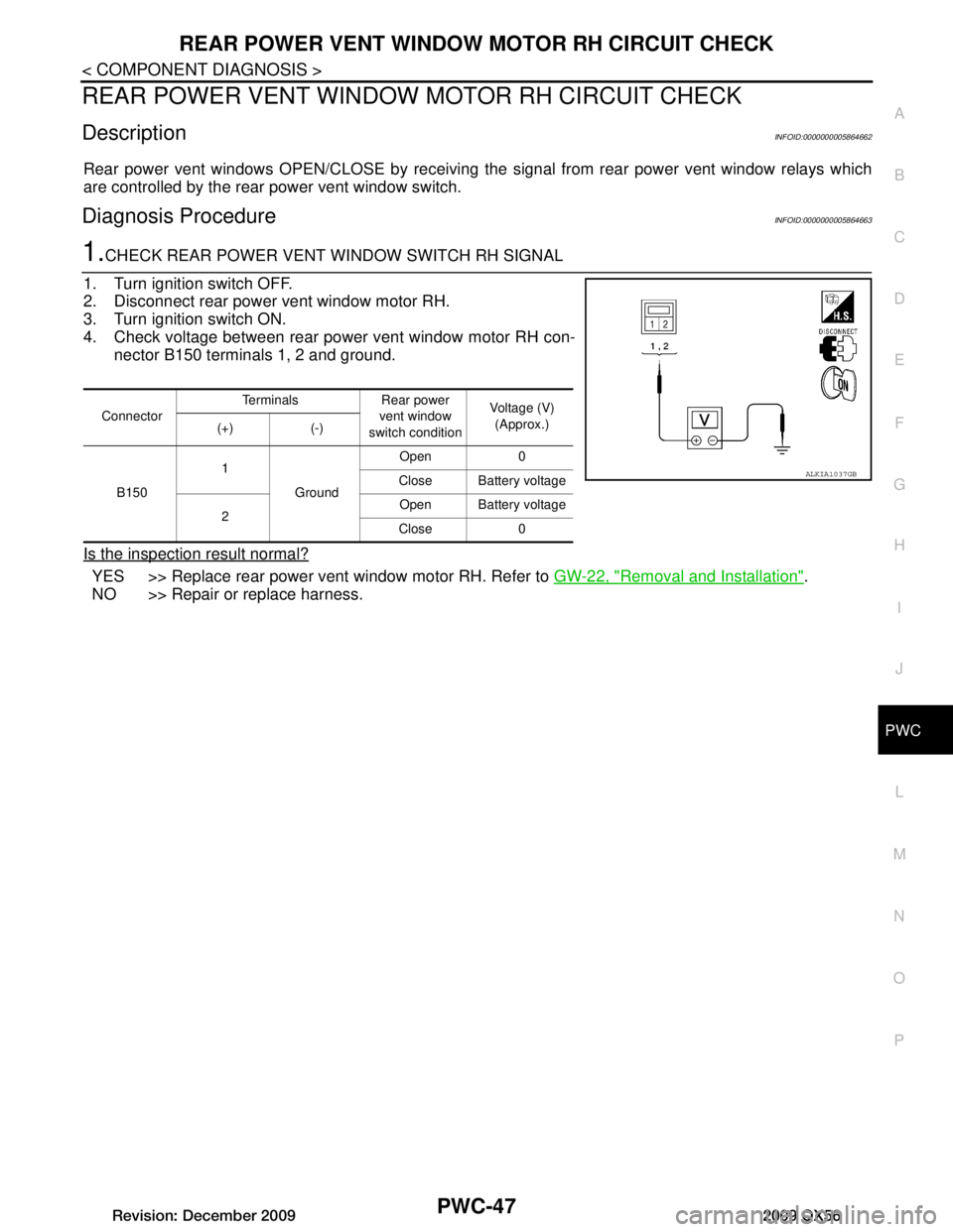
1.CHECK REAR POWER VENT WINDOW SWITCH RH SIGNAL
1. Turn ignition switch OFF.
2. Disconnect rear power vent window motor RH.
3. Turn ignition switch ON.
4. Check voltage between rear power vent window motor RH con- nector B150 terminals 1, 2 and ground.
Is the inspection result normal?
YES >> Replace rear power vent window motor RH. Refer to GW-22, "Removal and Installation".
NO >> Repair or replace harness.
Connector Terminals Rear power
vent window
switch condition Voltage (V)
(Approx.)
(+) (-)
B150 1
Ground Open 0
Close Battery voltage
2 Open Battery voltage
Close 0
ALKIA1037GB
Revision: December 20092009 QX56
Page 2996 of 4171
PWC-48
< COMPONENT DIAGNOSIS >
REAR POWER VENT WINDOW RELAY (OPEN) CHECK
REAR POWER VENT WINDOW RELAY (OPEN) CHECK
DescriptionINFOID:0000000005864664
Rear power vent windows OPEN/CLOSE by receiving the signal from rear power vent window switch.
Diagnosis Procedure - (Early Production)INFOID:0000000005864665
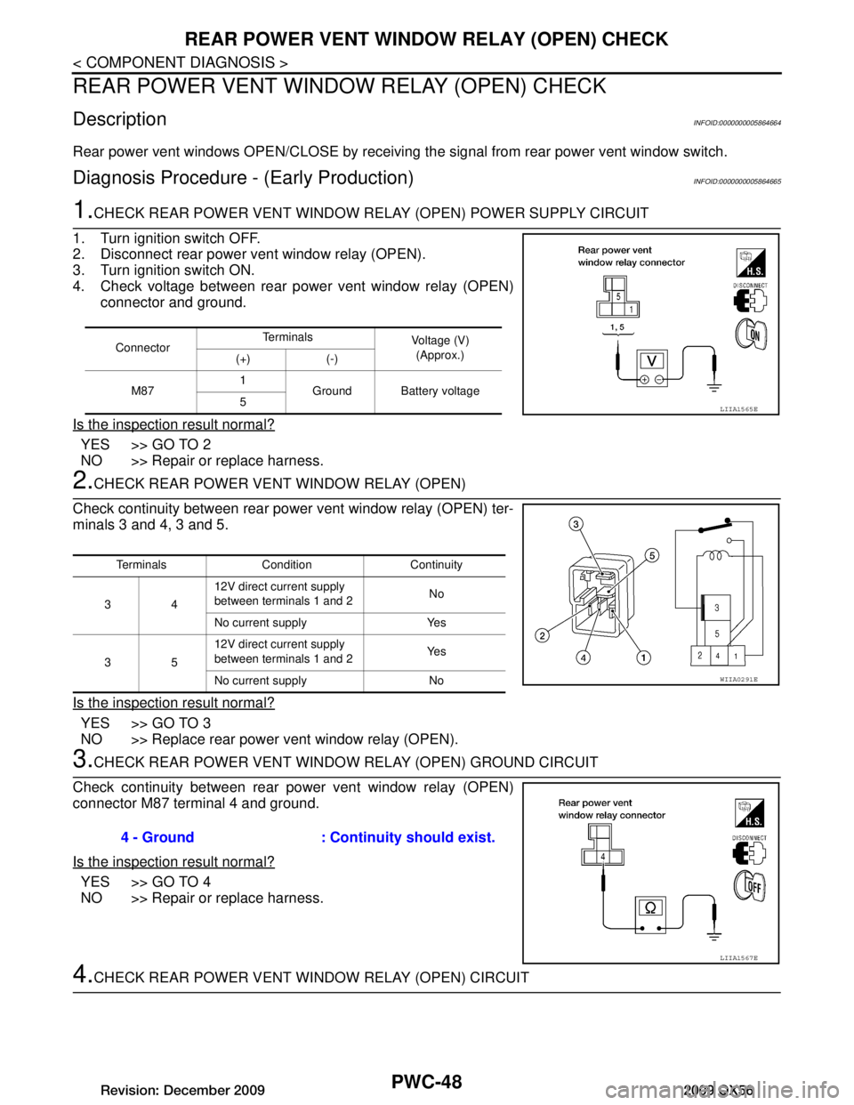
1.CHECK REAR POWER VENT WINDOW RELAY (OPEN) POWER SUPPLY CIRCUIT
1. Turn ignition switch OFF.
2. Disconnect rear power vent window relay (OPEN).
3. Turn ignition switch ON.
4. Check voltage between rear power vent window relay (OPEN) connector and ground.
Is the inspection result normal?
YES >> GO TO 2
NO >> Repair or replace harness.
2.CHECK REAR POWER VENT WINDOW RELAY (OPEN)
Check continuity between rear power vent window relay (OPEN) ter-
minals 3 and 4, 3 and 5.
Is the inspection result normal?
YES >> GO TO 3
NO >> Replace rear power vent window relay (OPEN).
3.CHECK REAR POWER VENT WINDO W RELAY (OPEN) GROUND CIRCUIT
Check continuity between rear power vent window relay (OPEN)
connector M87 terminal 4 and ground.
Is the inspection result normal?
YES >> GO TO 4
NO >> Repair or replace harness.
4.CHECK REAR POWER VENT WI NDOW RELAY (OPEN) CIRCUIT
ConnectorTe r m i n a l s
Voltage (V)
(Approx.)
(+) (-)
M87 1
Ground Battery voltage
5
LIIA1565E
Terminals Condition Continuity
34 12V direct current supply
between terminals 1 and 2
No
No current supply Yes
35 12V direct current supply
between terminals 1 and 2
Ye s
No current supply No
WIIA0291E
4 - Ground : Continuity should exist.
LIIA1567E
Revision: December 20092009 QX56
Page 2997 of 4171
REAR POWER VENT WINDOW RELAY (OPEN) CHECKPWC-49
< COMPONENT DIAGNOSIS >
C
DE
F
G H
I
J
L
M A
B
PWC
N
O P
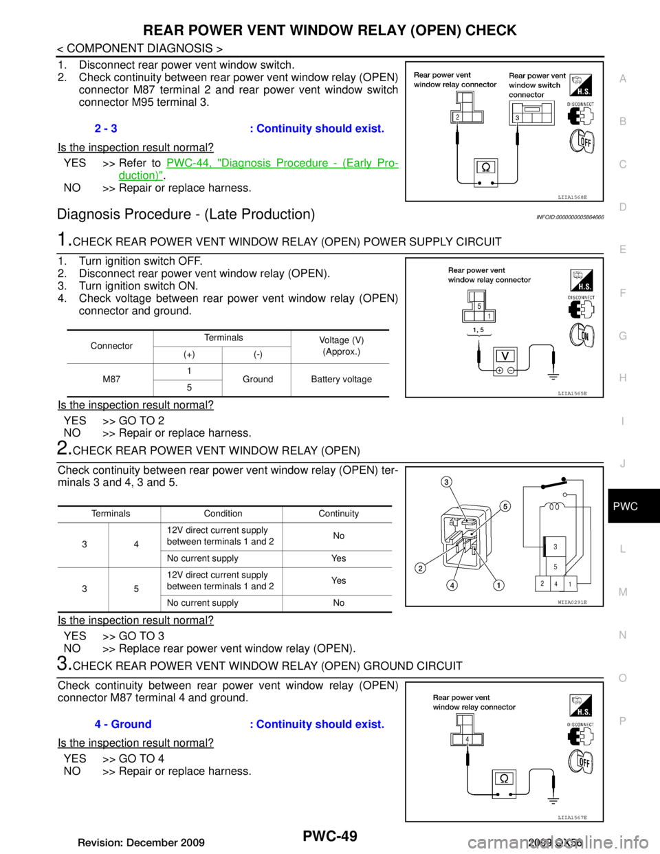
1. Disconnect rear power vent window switch.
2. Check continuity between rear power vent window relay (OPEN) connector M87 terminal 2 and rear power vent window switch
connector M95 terminal 3.
Is the inspection result normal?
YES >> Refer to PWC-44, "Diagnosis Procedure - (Early Pro-
duction)".
NO >> Repair or replace harness.
Diagnosis Procedure - (Late Production)INFOID:0000000005864666
1.CHECK REAR POWER VENT WINDOW RE LAY (OPEN) POWER SUPPLY CIRCUIT
1. Turn ignition switch OFF.
2. Disconnect rear power vent window relay (OPEN).
3. Turn ignition switch ON.
4. Check voltage between rear power vent window relay (OPEN) connector and ground.
Is the inspection result normal?
YES >> GO TO 2
NO >> Repair or replace harness.
2.CHECK REAR POWER VENT WINDOW RELAY (OPEN)
Check continuity between rear power vent window relay (OPEN) ter-
minals 3 and 4, 3 and 5.
Is the inspection result normal?
YES >> GO TO 3
NO >> Replace rear power vent window relay (OPEN).
3.CHECK REAR POWER VENT WINDO W RELAY (OPEN) GROUND CIRCUIT
Check continuity between rear power vent window relay (OPEN)
connector M87 terminal 4 and ground.
Is the inspection result normal?
YES >> GO TO 4
NO >> Repair or replace harness. 2 - 3 : Continuity should exist.
LIIA1568E
Connector
Te r m i n a l s
Voltage (V)
(Approx.)
(+) (-)
M87 1
Ground Battery voltage
5
LIIA1565E
Terminals Condition Continuity
34 12V direct current supply
between terminals 1 and 2
No
No current supply Yes
35 12V direct current supply
between terminals 1 and 2
Ye s
No current supply No
WIIA0291E
4 - Ground : Continuity should exist.
LIIA1567E
Revision: December 20092009 QX56