Page 2701 of 4171

MA-28
< ON-VEHICLE MAINTENANCE >
CHASSIS AND BODY MAINTENANCE
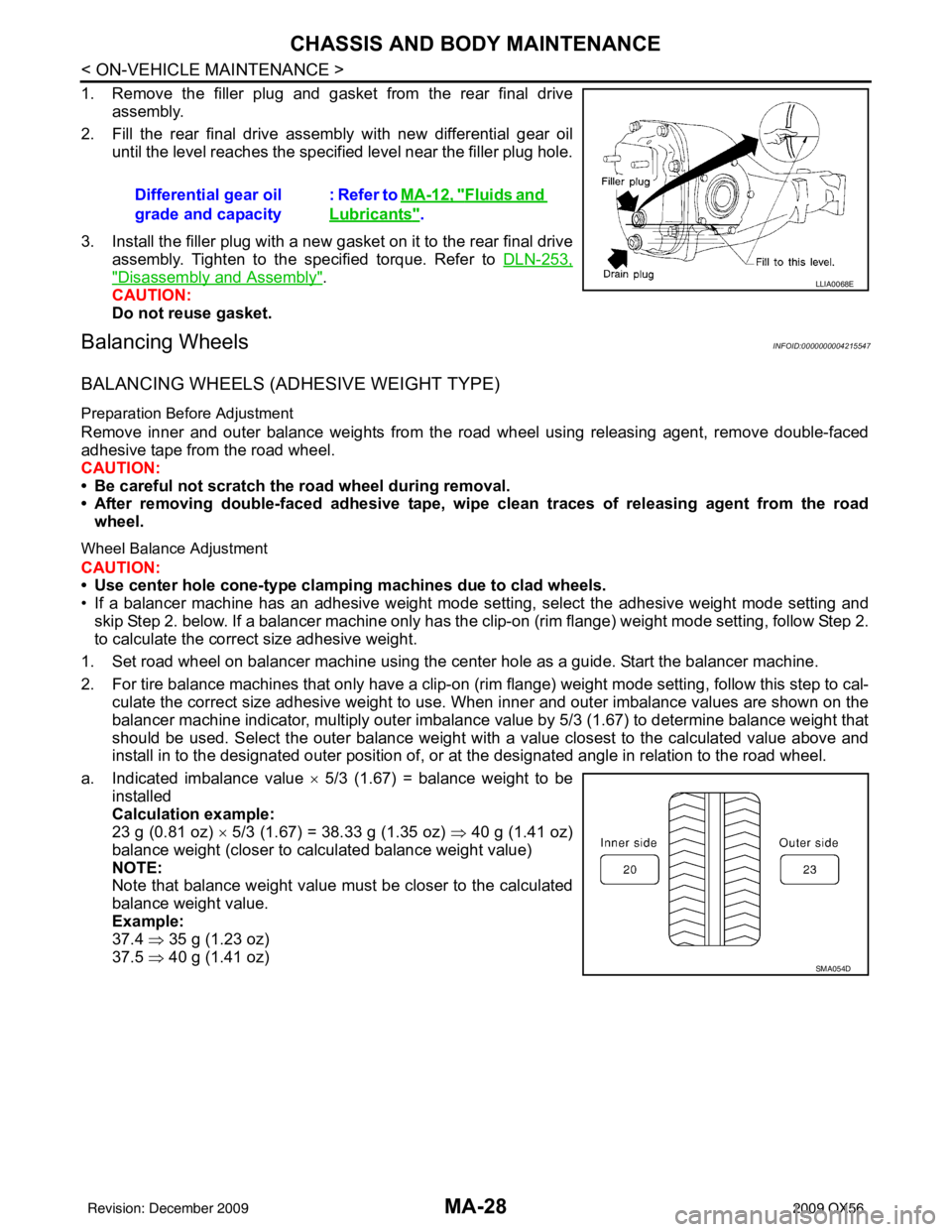
1. Remove the filler plug and gasket from the rear final driveassembly.
2. Fill the rear final drive assembly with new differential gear oil until the level reaches the specified level near the filler plug hole.
3. Install the filler plug with a new gasket on it to the rear final drive assembly. Tighten to the specified torque. Refer to DLN-253,
"Disassembly and Assembly".
CAUTION:
Do not reuse gasket.
Balancing WheelsINFOID:0000000004215547
BALANCING WHEELS (ADHESIVE WEIGHT TYPE)
Preparation Before Adjustment
Remove inner and outer balance weights from the road wheel using releasing agent, remove double-faced
adhesive tape from the road wheel.
CAUTION:
• Be careful not scratch the road wheel during removal.
• After removing double-faced adhesive tape, wipe clean traces of releasing agent from the road
wheel.
Wheel Balance Adjustment
CAUTION:
• Use center hole cone-type clamping machines due to clad wheels.
• If a balancer machine has an adhesive weight mode se tting, select the adhesive weight mode setting and
skip Step 2. below. If a balancer machine only has the clip-on (rim flange) weight mode setting, follow Step 2.
to calculate the correct size adhesive weight.
1. Set road wheel on balancer machine using the center hole as a guide. Start the balancer machine.
2. For tire balance machines that only have a clip-on (rim flange) weight mode setting, follow this step to cal- culate the correct size adhesive weight to use. When inner and outer imbalance values are shown on the
balancer machine indicator, multiply outer imbalance value by 5/3 (1.67) to determine balance weight that
should be used. Select the outer balance weight with a value closest to the calculated value above and
install in to the designated outer position of, or at the designated angle in relation to the road wheel.
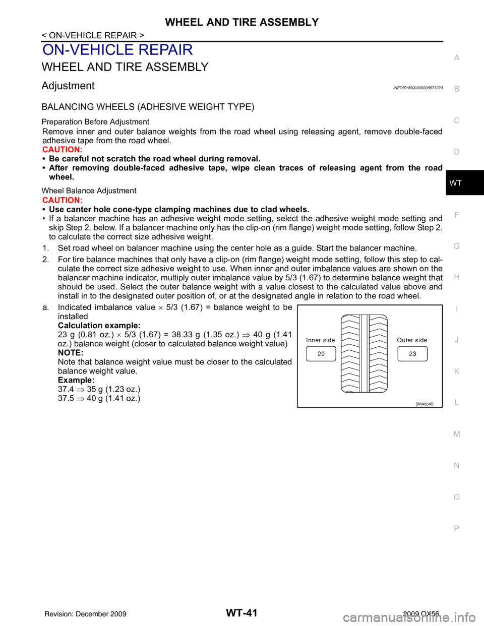
a. Indicated imbalance value × 5/3 (1.67) = balance weight to be
installed
Calculation example:
23 g (0.81 oz) × 5/3 (1.67) = 38.33 g (1.35 oz) ⇒ 40 g (1.41 oz)
balance weight (closer to calculated balance weight value)
NOTE:
Note that balance weight value must be closer to the calculated
balance weight value.
Example:
37.4 ⇒ 35 g (1.23 oz)
37.5 ⇒ 40 g (1.41 oz)
Differential gear oil
grade and capacity
: Refer to MA-12, "
Fluids and
Lubricants".
LLIA0068E
SMA054D
Revision: December 20092009 QX56
Page 4078 of 4171

WT-36
< SYMPTOM DIAGNOSIS >
NOISE, VIBRATION AND HARSHNESS (NVH) TROUBLESHOOTING
NOISE, VIBRATION AND HARSHNESS (NVH) TROUBLESHOOTING
NVH Troubleshooting ChartINFOID:0000000003772398
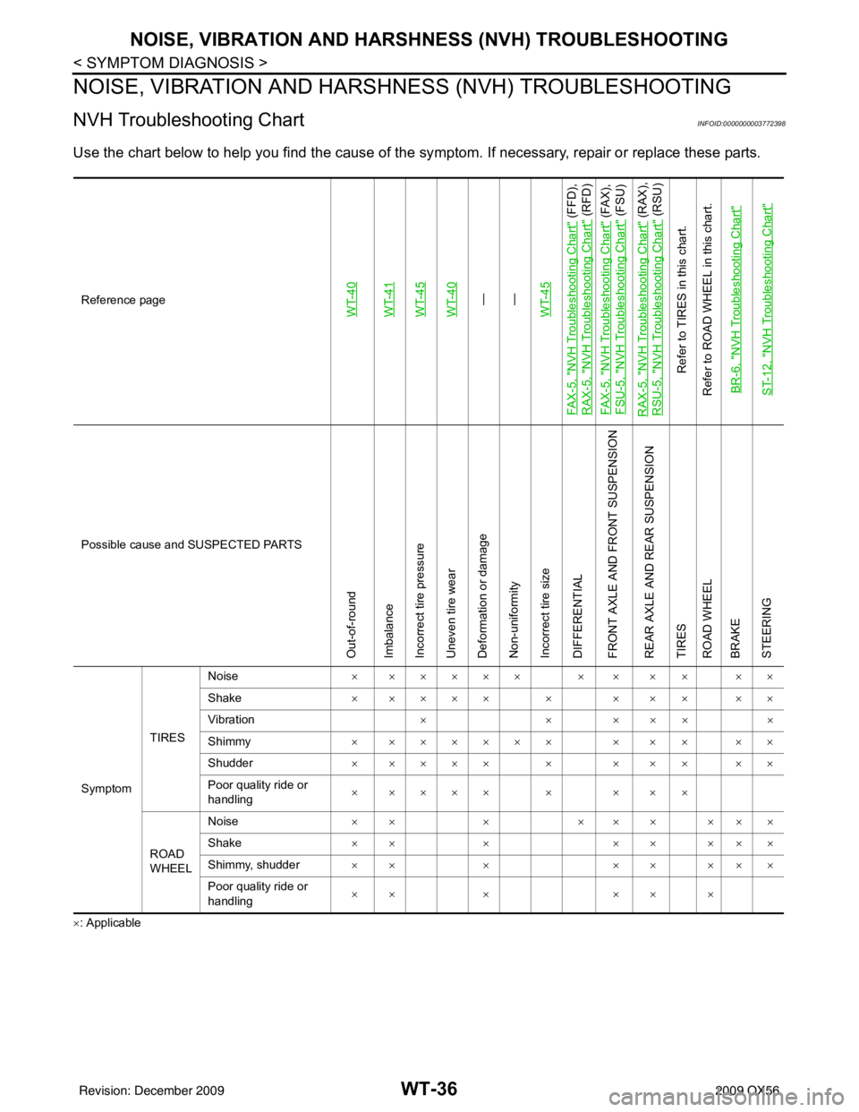
Use the chart below to help you find the cause of the sy mptom. If necessary, repair or replace these parts.
×: ApplicableReference page
WT-40WT-41WT-45WT-40—
—
WT-45
FA X - 5 , "
NVH Troubleshooting Chart
" (FFD),
RAX-5, "
NVH Troubleshooting Chart
" (RFD)
FA X - 5 , "
NVH Troubleshooting Chart
" (FAX),
FSU-5, "
NVH Troubleshooting Chart
" (FSU)
RAX-5, "
NVH Troubleshooting Chart
" (RAX),
RSU-5, "
NVH Troubleshooting Chart
" (RSU)
Refer to TIRES in this chart.
Refer to ROAD WHEEL in this chart.
BR-6, "
NVH Troubleshooting Chart
"
ST-12, "
NVH Troubleshooting Chart
"
Possible cause and SUSPECTED PARTS
Out-of-round
Imbalance
Incorrect tire pressure
Uneven tire wear
Deformation or damage
Non-uniformity
Incorrect tire size
DIFFERENTIAL
FRONT AXLE AND FRONT SUSPENSION
REAR AXLE AND REAR SUSPENSION
TIRES
ROAD WHEEL
BRAKE
STEERING
Symptom TIRESNoise
× ××××× × × × × ××
Shake × ×××× × × × × ××
Vibration ××× ×××
Shimmy × ×××××× × × × ××
Shudder × ×××× × × × × ××
Poor quality ride or
handling × ×××× × × × ×
ROAD
WHEEL Noise
×× × ××× ×××
Shake ×× × ×× ×××
Shimmy, shudder ×× × ×× ×××
Poor quality ride or
handling ×× ×
×× ×
Revision: December 20092009 QX56
Page 4083 of 4171

WHEEL AND TIRE ASSEMBLYWT-41
< ON-VEHICLE REPAIR >
C
DF
G H
I
J
K L
M A
B
WT
N
O P
ON-VEHICLE REPAIR
WHEEL AND TIRE ASSEMBLY
AdjustmentINFOID:0000000005873223
BALANCING WHEELS (ADH ESIVE WEIGHT TYPE)
Preparation Before Adjustment
Remove inner and outer balance weights from the r oad wheel using releasing agent, remove double-faced
adhesive tape from the road wheel.
CAUTION:
• Be careful not scratch the road wheel during removal.
• After removing double-faced adhesive tape, wipe clean traces of releasing agent from the road
wheel.
Wheel Balance Adjustment
CAUTION:
• Use canter hole cone-type clampi ng machines due to clad wheels.
• If a balancer machine has an adhesive weight mode setting, select the adhesive weight mode setting and
skip Step 2. below. If a balancer machine only has the clip-on (rim flange) weight mode setting, follow Step 2.
to calculate the correct size adhesive weight.
1. Set road wheel on balancer machine using the cent er hole as a guide. Start the balancer machine.
2. For tire balance machines that only have a clip-on (ri m flange) weight mode setting, follow this step to cal-
culate the correct size adhesive weight to use. When inner and outer imbalance values are shown on the
balancer machine indicator, multiply outer imbalance value by 5/3 (1.67) to determine balance weight that
should be used. Select the outer balance weight with a value closest to the calculated value above and
install in to the designated outer position of, or at the designated angle in relation to the road wheel.
a. Indicated imbalance value × 5/3 (1.67) = balance weight to be
installed
Calculation example:
23 g (0.81 oz.) × 5/3 (1.67) = 38.33 g (1.35 oz.) ⇒ 40 g (1.41
oz.) balance weight (closer to calculated balance weight value)
NOTE:
Note that balance weight value must be closer to the calculated
balance weight value.
Example:
37.4 ⇒ 35 g (1.23 oz.)
37.5 ⇒ 40 g (1.41 oz.)
SMA054D
Revision: December 20092009 QX56
Page 4087 of 4171
SERVICE DATA AND SPECIFICATIONS (SDS)WT-45
< SERVICE DATA AND SPECIFICATIONS (SDS)
C
DF
G H
I
J
K L
M A
B
WT
N
O P
SERVICE DATA AND SPECIFICATIONS (SDS)
SERVICE DATA AND SPECIFICATIONS (SDS)
Road WheelINFOID:0000000004201424
TireINFOID:0000000003772407
Unit: kPa (kg/cm2, psi)
Wheel type AluminumSte el
Inside Outside
Maximum radial
runout limit Lateral mm (in)
0.3 (0.012) or less 1.0 (0.039) or less 0.9 (0.035) or less
Radial mm (in) 0.3 (0.012) or less 0.8 (0.031) or less 0.4 (0.016) or less
Maximum residual im-
balance Dynamic (at rim flange)
Less than 5 g (0.18 oz) (per side)
Static (at rim flange) Less than 10 g (0.35 oz)
Tire size Air pressure
Conventional tire Spare tire
Full size spare tire —240 (2.4, 35)
P275/60R20 240 (2.4, 35)—
Revision: December 20092009 QX56