2009 INFINITI QX56 fuse
[x] Cancel search: fusePage 3412 of 4171
![INFINITI QX56 2009 Factory Service Manual SEC-102
< ECU DIAGNOSIS >[WITH INTELLIGENT KEY SYSTEM]
IPDM E/R (INTELLIGENT POWER DI
STRIBUTION MODULE ENGINE ROOM)
*: When horn reminder is ON
Fail SafeINFOID:0000000004221483
CAN COMMUNICATION CONT INFINITI QX56 2009 Factory Service Manual SEC-102
< ECU DIAGNOSIS >[WITH INTELLIGENT KEY SYSTEM]
IPDM E/R (INTELLIGENT POWER DI
STRIBUTION MODULE ENGINE ROOM)
*: When horn reminder is ON
Fail SafeINFOID:0000000004221483
CAN COMMUNICATION CONT](/manual-img/42/57031/w960_57031-3411.png)
SEC-102
< ECU DIAGNOSIS >[WITH INTELLIGENT KEY SYSTEM]
IPDM E/R (INTELLIGENT POWER DI
STRIBUTION MODULE ENGINE ROOM)
*: When horn reminder is ON
Fail SafeINFOID:0000000004221483
CAN COMMUNICATION CONTROL
When CAN communication with ECM and BCM is impossible, IPDM E/R performs fail-safe control. After CAN
communication recovers normally, it also returns to normal control.
If No CAN Communication Is Available With ECM
If No CAN Communication Is Available With BCM
IGNITION RELAY MALFUNCTION DETECTION FUNCTION
• IPDM E/R monitors the voltage at the contact circuit and excitation coil circuit of the ignition relay inside it.
• IPDM E/R judges the ignition relay error if the voltage differs between the contact circuit and the excitation
coil circuit.
• If the ignition relay cannot turn OFF due to contact seizure, it activates the tail lamp relay for 10 minutes to alert the user to the ignition relay malfunction when the ignition switch is turned OFF.
NOTE:
The tail lamp turns OFF when the ignition switch is turned ON.
FRONT WIPER CONTROL
IPDM E/R detects front wiper stop posit ion by a front wiper auto stop signal.
59 B Ground Input ——0V
60 B/W Rear window defog-
ger relay
OutputON or
START Rear defogger switch ON
Battery voltage
Rear defogger switch OFF 0V
61 BR Fuse 32 Output OFF—Battery voltage
Te r m i n a l
Wire
color Signal name Signal
input/
output Measuring condition
Reference value(Approx.)
Igni-
tion
switch Operation or condition
Control part
Fail-safe in operation
Cooling fan • Turns ON the cooling fan relay when the ignition switch is turned ON
• Turns OFF the cooling fan relay when the ignition switch is turned OFF
Control part
Fail-safe in operation
Headlamp • Turns ON the headlamp low relay when the ignition switch is turned ON
• Turns OFF the headlamp low relay when the ignition switch is turned OFF
• Headlamp high relay OFF
•Parking lamps
• License plate lamps
• Tail lamps • Turns ON the tail lamp relay when the ignition switch is turned ON
• Turns OFF the tail lamp relay when the ignition switch is turned OFF
Front wiper • The status just before activation of fail-safe control is maintained until the ignition
switch is turned OFF while the front wiper is operating at LO or HI speed.
• The wiper is operated at LO speed until the ignition switch is turned OFF if the fail- safe control is activated while the front wipe r is set in the INT mode and the front wiper
motor is operating.
Rear window defogger Rear window defogger relay OFF
A/C compressor A/C relay OFF
Front fog lamps Front fog lamp relay OFF
Ignition switch Ignition relayTail lamp relay
ON ON —
OFF OFF —
Revision: December 20092009 QX56
Page 3435 of 4171
SN
POWER SUPPLY AND GROUND CIRCUITSN-13
< COMPONENT DIAGNOSIS >
C
DE
F
G H
I
J
K L
M B A
O P
COMPONENT DIAGNOSIS
POWER SUPPLY AND GROUND CIRCUIT
Diagnosis Procedure (With Rear Sonar System)INFOID:0000000004173800
INSPECTION FOR POWER SUPPLY AND GROUND CIRCUIT
1.CHECK FUSES
Check for blown rear sonar system fuses.
Are any fuses blown?
YES >> If fuse is blown, be sure to eliminate cause of malfunction before installing new fuse. Refer to GI-
41, "Circuit Inspection".
NO >> GO TO 2.
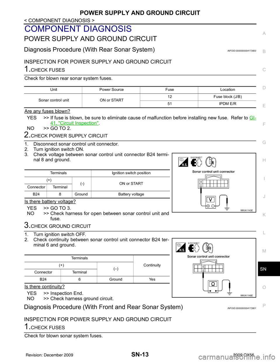
2.CHECK POWER SUPPLY CIRCUIT
1. Disconnect sonar control unit connector.
2. Turn ignition switch ON.
3. Check voltage between sonar control unit connector B24 termi- nal 8 and ground.
Is there battery voltage?
YES >> GO TO 3.
NO >> Check harness for open between sonar control unit and fuse.
3.CHECK GROUND CIRCUIT
1. Turn ignition switch OFF.
2. Check continuity between sonar control unit connector B24 ter- minal 6 and ground.
Is there continuity?
YES >> Inspection End.
NO >> Check harness ground circuit.
Diagnosis Procedure (With Front and Rear Sonar System)INFOID:0000000004173801
INSPECTION FOR POWER SUPPLY AND GROUND CIRCUIT
1.CHECK FUSES
Check for blown sonar system fuses.
Unit Power Source FuseLocation
Sonar control unit ON or START 12
Fuse block (J/B)
51 IPDM E/R
Terminals Ignition switch position
(+) (-) ON or START
Connector Terminal
B24 8 Ground Battery voltage
WKIA1145E
Te r m i n a l s
Continuity
(+)
(–)
Connector Terminal
B24 6 Ground Yes
WKIA1146E
Revision: December 20092009 QX56
Page 3436 of 4171
SN-14
< COMPONENT DIAGNOSIS >
POWER SUPPLY AND GROUND CIRCUIT
Are any fuses blown?
YES >> If fuse is blown, be sure to eliminate cause of malfunction before installing new fuse. Refer to GI-
41, "Circuit Inspection".
NO >> GO TO 2.
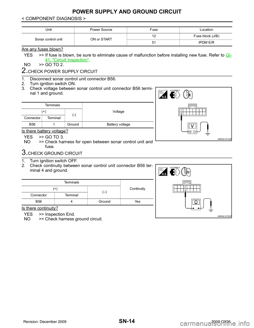
2.CHECK POWER SUPPLY CIRCUIT
1. Disconnect sonar control unit connector B56.
2. Turn ignition switch ON.
3. Check voltage between sonar control unit connector B56 termi- nal 1 and ground.
Is there battery voltage?
YES >> GO TO 3.
NO >> Check harness for open between sonar control unit and fuse.
3.CHECK GROUND CIRCUIT
1. Turn ignition switch OFF.
2. Check continuity between sonar control unit connector B56 ter-
minal 4 and ground.
Is there continuity?
YES >> Inspection End.
NO >> Check harness ground circuit.
Unit Power Source FuseLocation
Sonar control unit ON or START 12
Fuse block (J/B)
51 IPDM E/R
Te r m i n a l s
Vo l ta g e
(+)
(-)
Connector Terminal
B56 1 Ground Battery voltage
AWNIA1574ZZ
Te r m i n a l s
Continuity
(+)
(–)
Connector Terminal
B56 4Ground Yes
AWNIA1575ZZ
Revision: December 20092009 QX56
Page 3511 of 4171
ON BOARD DIAGNOSTIC (OBD) SYSTEMSRC-13
< FUNCTION DIAGNOSIS >
C
DE
F
G
I
J
K L
M A
B
SRC
N
O P
ON BOARD DIAGNOSTIC (OBD) SYSTEM
Trouble Diagnosis IntroductionINFOID:0000000003775184
CAUTION:
• Do not use electrical test equipment on any circui t related to the SRS unless instructed to do so in
this Service Manual. SRS wiring harnesses can be id entified by yellow and/or orange harness con-
nectors.
• Do not attempt to repair, splice or modify SRS wiring harnesses. If a harness is damaged, replace it
with a new one.
• Keep ground connections clean.
DIAGNOSIS FUNCTION
The SRS self-diagnosis results can be read by usi ng “AIR BAG” warning lamp and/or CONSULT-III.
The User mode is exclusively prepared for the customer (driver). This mode warns the driver of a system mal-
function through the operation of the “AIR BAG” warning lamp.
The Diagnosis mode allows the technician to locate and inspect the malfunctioning part.
The mode applications for the “AIR BAG” warning lamp and CONSULT-III are as follows:
HOW TO PERFORM TROUBLE DIAGNOSES FOR QUICK AND ACCURATE REPAIR
A good understanding of the malfunction conditions can make troubleshooting faster and more accurate.
In general, each customer feels differently about a malf unction. It is important to fully understand the symp-
toms or conditions for a customer complaint.
Information From Customer
WHAT - Vehicle model
WHEN - Date, Frequencies
WHERE - Road conditions
HOW - Operating conditions, Symptoms
Preliminary Check
Check that the following parts are in good order.
•Battery
•Fuse
• System component-to-harness connections
SRS Operation CheckINFOID:0000000003775185
DIAGNOSTIC PROCEDURE 1
Checking SRS Operation Using “AIR BAG” Warning Lamp—User Mode
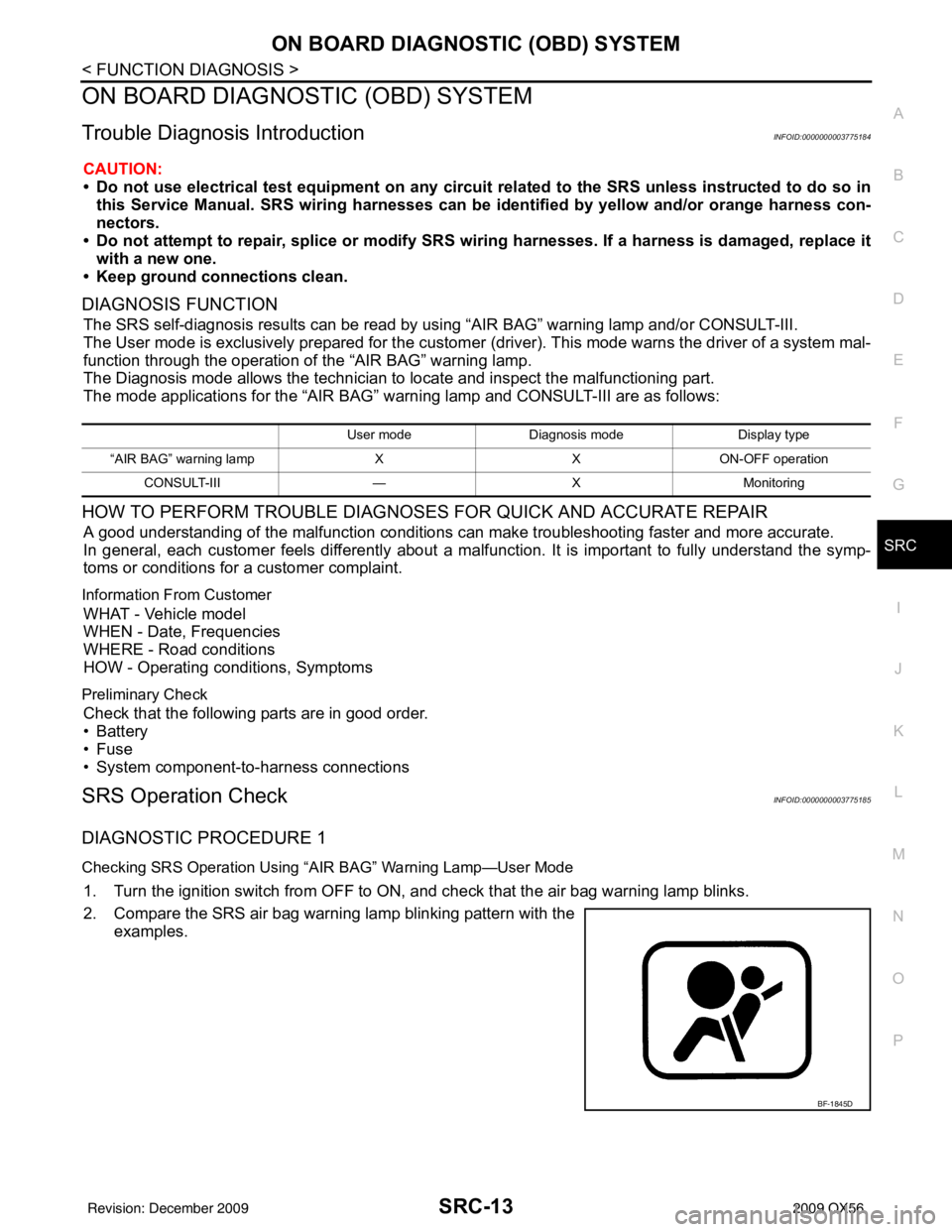
1. Turn the ignition switch from OFF to ON, and check that the air bag warning lamp blinks.
2. Compare the SRS air bag warning lamp blinking pattern with the examples.
User mode Diagnosis mode Display type
“AIR BAG” warning lamp XXON-OFF operation
CONSULT-III —XMonitoring
BF-1845D
Revision: December 20092009 QX56
Page 3588 of 4171
SRC-90
< SYMPTOM DIAGNOSIS >
SRS AIR BAG SYSTEM
SYMPTOM DIAGNOSIS
SRS AIR BAG SYSTEM
"AIR BAG" Warning Lamp Does Not Turn OffINFOID:0000000003775249
DIAGNOSTIC PROCEDURE 7
1.CHECK CONDITION OF AIR BAG MODULE
Inspect for any deployed air bag modules or seat belt pre-tensioners.
Are any air bag modules or s eat belt pre-tensioners deployed?
YES >> Refer to SR-20, "For Frontal Collision" or SR-22, "For Side and Rollover Collision".
NO >> GO TO 2
2.CHECK THE AIR BAG FUSE
Check 10A fuse [No. 13, locat ed in the fuse block (J/B)].
Is the fuse blown?
Ye s > > G O T O 3
No >> GO TO 4
3.CHECK AIR BAG FUSE AGAIN
Replace 10A fuse [No. 13, located in the fu se block (J/B)] and turn ignition switch ON.
Does the fuse blow again?
YES >> Replace harness.
NO >> Inspection End.
4.CHECK AIR BAG DIAGNOSIS SENSOR UNIT
Connect CONSULT-III.
Is
“AIR BAG” displayed on CONSULT-III?
YES >> GO TO 5
NO >> Visually inspect the air bag diagnosis sensor unit harness connections. If the connections are OK,
replace the air bag diagnosis sensor unit. Refer to SR-17, "
Removal and Installation".
5.CHECK HARNESS CONNECTION
Check for loose connections between the combination meter and the air bag diagnosis sensor unit.
Are there any loose connections?
Yes >> Properly connect the combination meter and air bag diagnosis sensor unit harness connectors. If
“AIR BAG” warning lamp still does not turn off, replace the wiring harness.
No >> Replace air bag diagnosis sensor unit.
"AIR BAG" Warning La mp Does Not Turn OnINFOID:0000000003775250
DIAGNOSTIC PROCEDURE 8
1.CHECK METER FUSE
Check the 10A fuse [No. 14, located in the fuse block (J/B)] .
Is the fuse blown?
Ye s > > G O T O 2
No >> GO TO 3
2.REPLACE METER FUSE AND CHECK AGAIN
Replace 10A fuse [No. 14, located in the fu se block (J/B)] and turn ignition switch ON.
Does the fuse blow again?
Yes >> Replace harness.
No >> Inspection End.
3.CHECK HARNESS CONNECTIONS BET WEEN AIR BAG DIAGNOSIS SENSOR UNIT AND COMBINA-
Revision: December 20092009 QX56
Page 3590 of 4171
SRC-92
< SYMPTOM DIAGNOSIS >
PASSENGER SEAT BELT WARNING SYSTEM
PASSENGER SEAT BELT WARNING SYSTEM
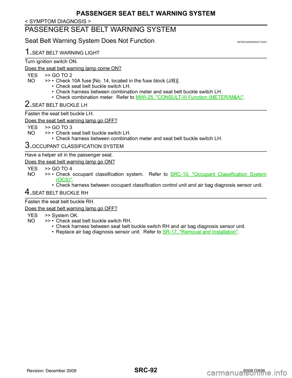
Seat Belt Warning System Does Not FunctionINFOID:0000000003775251
1.SEAT BELT WARNING LIGHT
Turn ignition switch ON.
Does the seat belt warning lamp come ON?
YES >> GO TO 2
NO >> • Check 10A fuse [No. 14, located in the fuse block (J/B)]. • Check seat belt buckle switch LH.
• Check harness between combination meter and seat belt buckle switch LH.
• Check combination meter. Refer to MWI-25, "
CONSULT-III Function (METER/M&A)".
2.SEAT BELT BUCKLE LH
Fasten the seat belt buckle LH.
Does the seat belt warning lamp go OFF?
YES >> GO TO 3
NO >> • Check seat belt buckle switch LH. • Check harness between combination meter and seat belt buckle switch LH.
3.OCCUPANT CLASSIFICATION SYSTEM
Have a helper sit in the passenger seat.
Does the seat belt warning lamp go ON?
YES >> GO TO 4
NO >> • Check occupant classification system. Refer to SRC-10, "
Occupant Classification System
(OCS)".
• Check harness between occupant classification control unit and air bag diagnosis sensor unit.
4.SEAT BELT BUCKLE RH
Fasten the seat belt buckle RH.
Does the seat belt warning lamp go OFF?
YES >> System OK.
NO >> • Check seat belt buckle switch RH. • Check harness between seat belt buckle switch RH and air bag diagnosis sensor unit.
• Replace air bag diagnosis sensor unit. Refer to SR-17, "
Removal and Installation".
Revision: December 20092009 QX56
Page 3639 of 4171
STR-10
< COMPONENT DIAGNOSIS >
B TERMINAL CIRCUIT
COMPONENT DIAGNOSIS
B TERMINAL CIRCUIT
DescriptionINFOID:0000000003771792
Terminal "2" (B) is constantly supplied with battery power.
Diagnosis ProcedureINFOID:0000000003771793
CAUTION:
Perform diagnosis under the condition that the engine cannot start by the following procedure.
1. Remove fuel pump fuse.
2. Crank or start the engine (where possible) until the fuel pressure is depleted.
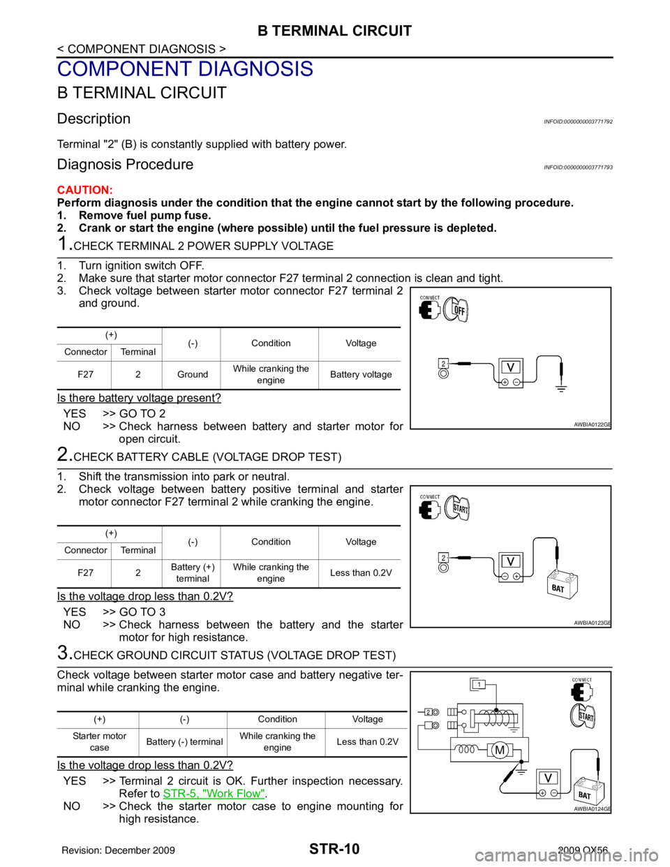
1.CHECK TERMINAL 2 POWER SUPPLY VOLTAGE
1. Turn ignition switch OFF.
2. Make sure that starter motor connector F27 terminal 2 connection is clean and tight.
3. Check voltage between starter motor connector F27 terminal 2
and ground.
Is there battery voltage present?
YES >> GO TO 2
NO >> Check harness between battery and starter motor for open circuit.
2.CHECK BATTERY CABLE (VOLTAGE DROP TEST)
1. Shift the transmission into park or neutral.
2. Check voltage between battery positive terminal and starter motor connector F27 terminal 2 while cranking the engine.
Is the voltage drop less than 0.2V?
YES >> GO TO 3
NO >> Check harness between the battery and the starter motor for high resistance.
3.CHECK GROUND CIRCUIT STATUS (VOLTAGE DROP TEST)
Check voltage between starter motor case and battery negative ter-
minal while cranking the engine.
Is the voltage drop less than 0.2V?
YES >> Terminal 2 circuit is OK. Further inspection necessary. Refer to STR-5, "
Work Flow".
NO >> Check the starter motor case to engine mounting for high resistance.
(+) (-)Condition Voltage
Connector Terminal
F27 2 Ground While cranking the
engine Battery voltage
AWBIA0122GB
(+)
(-)Condition Voltage
Connector Terminal
F27 2 Battery (+)
terminal While cranking the
engine Less than 0.2V
AWBIA0123GB
(+)
(-)Condition Voltage
Starter motor case Battery (-) terminal
While cranking the
engine Less than 0.2V
AWBIA0124GB
Revision: December 20092009 QX56
Page 3640 of 4171
S CONNECTOR CIRCUITSTR-11
< COMPONENT DIAGNOSIS >
C
DE
F
G H
I
J
K L
M A
STR
NP
O
S CONNECTOR CIRCUIT
DescriptionINFOID:0000000003771794
Terminal "1" (S) is the power supply for the starter mo
tor magnetic switch. Terminal 1 is supplied with power
when the ignition switch is turned to the START position while the selector lever is in the P or N position.
Diagnosis ProcedureINFOID:0000000003771795
CAUTION:
Perform diagnosis under the cond ition that engine cannot start by the following procedure.
1. Remove fuel pump fuse.
2. Crank or start the engine (where possi ble) until the fuel pressure is released.
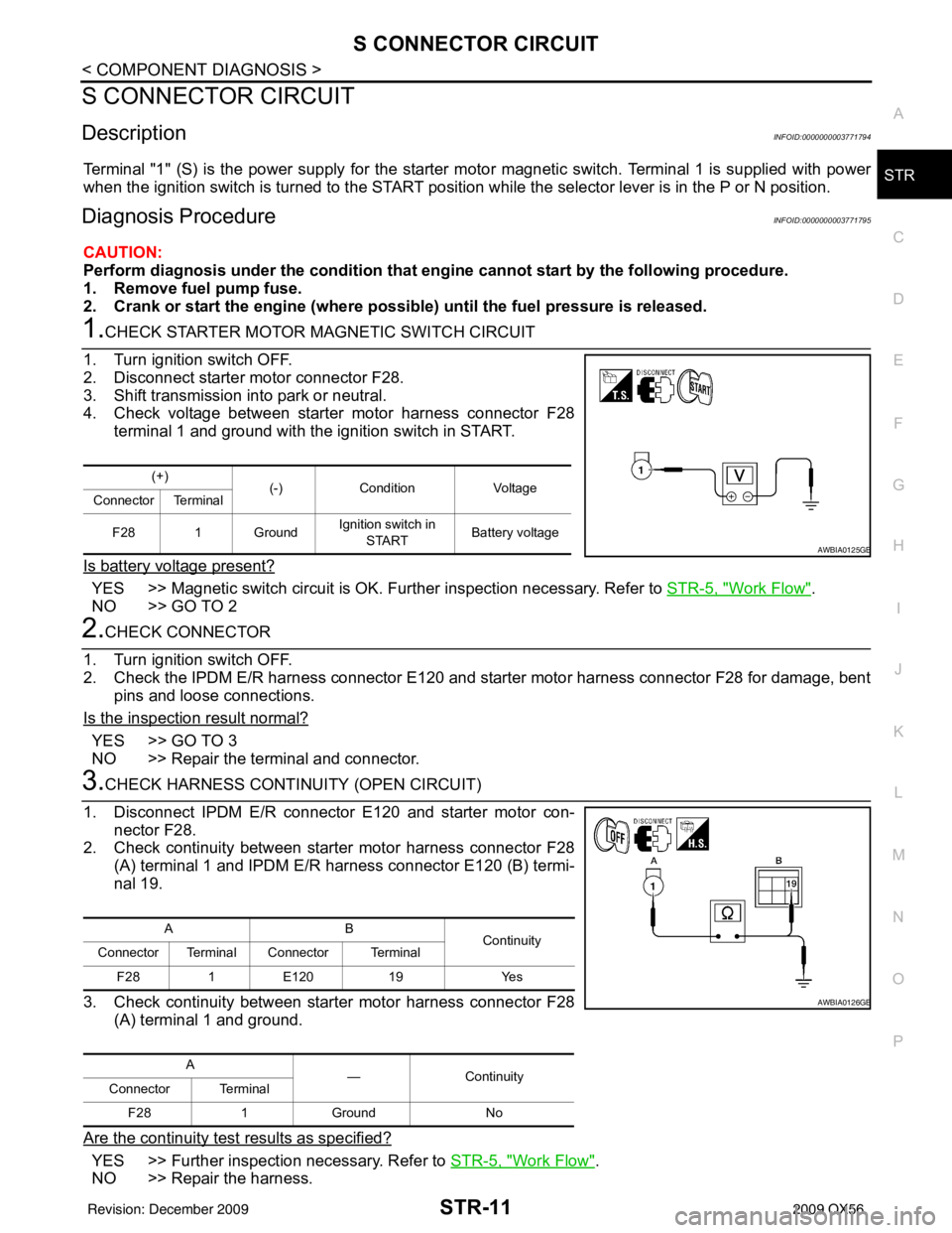
1.CHECK STARTER MOTOR MAGNETIC SWITCH CIRCUIT
1. Turn ignition switch OFF.
2. Disconnect starter motor connector F28.
3. Shift transmission into park or neutral.
4. Check voltage between starter motor harness connector F28 terminal 1 and ground with the ignition switch in START.
Is battery voltage present?
YES >> Magnetic switch circuit is OK. Further inspection necessary. Refer to STR-5, "Work Flow".
NO >> GO TO 2
2.CHECK CONNECTOR
1. Turn ignition switch OFF.
2. Check the IPDM E/R harness connector E120 and starter motor harness connector F28 for damage, bent pins and loose connections.
Is the inspection result normal?
YES >> GO TO 3
NO >> Repair the terminal and connector.
3.CHECK HARNESS CONTI NUITY (OPEN CIRCUIT)
1. Disconnect IPDM E/R connector E120 and starter motor con- nector F28.
2. Check continuity between starter motor harness connector F28 (A) terminal 1 and IPDM E/R harness connector E120 (B) termi-
nal 19.
3. Check continuity between starter motor harness connector F28 (A) terminal 1 and ground.
Are the continuity test results as specified?
YES >> Further inspection necessary. Refer to STR-5, "Work Flow".
NO >> Repair the harness.
(+) (-)Condition Voltage
Connector Terminal
F28 1 Ground Ignition switch in
START Battery voltage
AWBIA0125GB
AB
Continuity
Connector Terminal Connector Terminal
F28 1E120 19 Yes
A —Con tin uit y
Connector Terminal
F28 1Ground No
AWBIA0126GB
Revision: December 20092009 QX56