2009 INFINITI QX56 ignition
[x] Cancel search: ignitionPage 3677 of 4171

A/T SHIFT LOCK SYSTEMTM-29
< FUNCTION DIAGNOSIS >
CEF
G H
I
J
K L
M A
B
TM
N
O P
A/T SHIFT LOCK SYSTEM
System DescriptionINFOID:0000000003771817
The electrical key interlock mechanism also operates as a shift lock: With the ignition switch turned to ON, the selector lever cannot be shifted from “P” (parking) to any other
position unless the brake pedal is depressed.
With the key removed, the selector lever c annot be shifted from “P” to any other position.
The key cannot be removed unless the selector lever is placed in “P”.
The shift lock and key interlock mechanisms are controlled by the ON-OFF operation of the shift lock sole-
noid and by the operation of the rotator and slider located inside the key cylinder, respectively.
Component Parts LocationINFOID:0000000003771818
LCIA0326E
Revision: December 20092009 QX56
Page 3679 of 4171
ON BOARD DIAGNOSTIC (OBD) SYSTEMTM-31
< FUNCTION DIAGNOSIS >
CEF
G H
I
J
K L
M A
B
TM
N
O P
longer stored. Remember, only one set of freeze frame data can be stored in the ECM. The ECM has the fol-
lowing priorities to update the data.
Both 1st trip freeze frame data and freeze frame data (along with the DTC) are cleared when the ECM mem-
ory is erased.
HOW TO ERASE DTC
The diagnostic trouble code can be erased by CONSULT- III, GST or ECM DIAGNOSTIC TEST MODE as
described following.
If the battery cable is disconnected, the diagnostic trouble code will be lost within 24 hours.
When you erase the DTC, using CONSULT-III or GS T is easier and quicker than switching the mode
selector on the ECM.
The following emission-related diagnostic information is cleared from the ECM memory when erasing DTC
related to OBD-II. For details, refer to EC-42, "Emission-related Diagnostic Information"
.
Diagnostic trouble codes (DTC)
1st trip diagnostic trouble codes (1st trip DTC)
Freeze frame data
1st trip freeze frame data
System readiness test (SRT) codes
Test values
HOW TO ERASE DTC (WITH CONSULT-III)
1. The emission related diagnostic information in the TCM and ECM can be er\
ased by selectioning "ALL
ERASE" in the "Description" of "F INAL CHECK" mode with CONSULT-III.
HOW TO ERASE DTC (WITH GST)
1. If the ignition switch stays “ON” after repair work, be sure to turn ignition switch “OFF” once. Wait at least
10 seconds and then turn it “ON” (engine stopped) again.
2. Select Mode 4 with the Generic Scan Tool (GST). For details refer to EC-72, "Generic Scan Tool (GST)
Function".
HOW TO ERASE DTC (NO TOOLS)
1. Disconnect battery for 24 hours.
2. Reconnect battery.
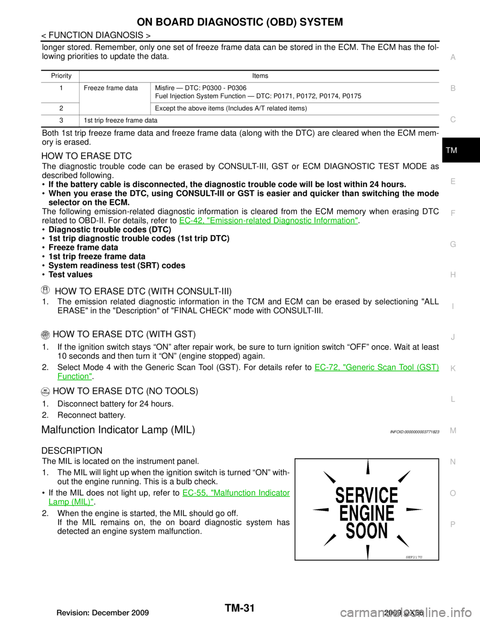
Malfunction Indicator Lamp (MIL)INFOID:0000000003771823
DESCRIPTION
The MIL is located on the instrument panel.
1. The MIL will light up when the ignition switch is turned “ON” with-
out the engine running. This is a bulb check.
If the MIL does not light up, refer to EC-55, "Malfunction Indicator
Lamp (MIL)".
2. When the engine is start ed, the MIL should go off.
If the MIL remains on, the on board diagnostic system has
detected an engine system malfunction.
Priority Items
1 Freeze frame data Misfire — DTC: P0300 - P0306 Fuel Injection System Function — DTC: P0171, P0172, P0174, P0175
2 Except the above items (Includes A/T related items)
3 1st trip freeze frame data
SEF217U
Revision: December 20092009 QX56
Page 3680 of 4171
TM-32
< FUNCTION DIAGNOSIS >
DIAGNOSIS SYSTEM (TCM)
DIAGNOSIS SYSTEM (TCM)
CONSULT-III Function (TRANSMISSION)INFOID:0000000004019470
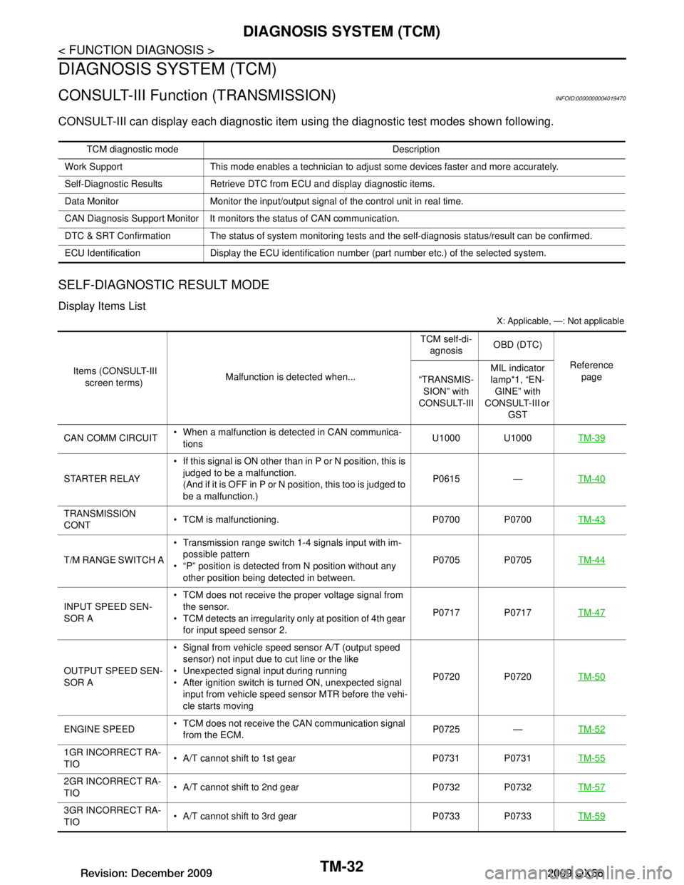
CONSULT-III can display each diagnostic item using the diagnostic test modes shown following.
SELF-DIAGNOSTIC RESULT MODE
Display Items List
X: Applicable, —: Not applicable
TCM diagnostic mode Description
Work Support This mode enables a technician to adjust some devices faster and more accurately.
Self-Diagnostic Results Retrieve DTC from ECU and display diagnostic items.
Data Monitor Monitor the input/output signal of the control unit in real time.
CAN Diagnosis Support Monitor It monitors the status of CAN communication.
DTC & SRT Confirmation The status of system monitoring tests and the self-diagnosis status/result can be confirmed.
ECU Identification Display the ECU identification nu mber (part number etc.) of the selected system.
Items (CONSULT-III
screen terms) Malfunction is detected when... TCM self-di-
agnosis OBD (DTC)
Reference page
“TRANSMIS-
SION” with
CONSULT-III MIL indicator
lamp*1, “EN-
GINE” with
CONSULT-III or
GST
CAN COMM CIRCUIT When a malfunction is detected in CAN communica-
tions U1000 U1000
TM-39
STARTER RELAY If this signal is ON other than in P or N position, this is
judged to be a malfunction.
(And if it is OFF in P or N position, this too is judged to
be a malfunction.) P0615 —
TM-40
TRANSMISSION
CONT TCM is malfunctioning. P0700 P0700
TM-43
T/M RANGE SWITCH A Transmission range switch 1-4 signals input with im-
possible pattern
“P” position is detected from N position without any other position being detected in between. P0705 P0705
TM-44
INPUT SPEED SEN-
SOR A TCM does not receive the proper voltage signal from
the sensor.
TCM detects an irregularity only at position of 4th gear for input speed sensor 2. P0717 P0717
TM-47
OUTPUT SPEED SEN-
SOR A Signal from vehicle speed sensor A/T (output speed
sensor) not input due to cut line or the like
Unexpected signal input during running
After ignition switch is turned ON, unexpected signal input from vehicle speed sensor MTR before the vehi-
cle starts moving P0720 P0720
TM-50
ENGINE SPEED TCM does not receive the CAN communication signal
from the ECM. P0725 —
TM-52
1GR INCORRECT RA-
TIO A/T cannot shift to 1st gear P0731 P0731
TM-55
2GR INCORRECT RA-
TIO A/T cannot shift to 2nd gear P0732 P0732
TM-57
3GR INCORRECT RA-
TIO A/T cannot shift to 3rd gear P0733 P0733
TM-59
Revision: December 20092009 QX56
Page 3685 of 4171
DIAGNOSIS SYSTEM (TCM)TM-37
< FUNCTION DIAGNOSIS >
CEF
G H
I
J
K L
M A
B
TM
N
O P
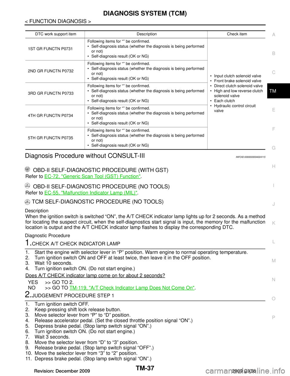
Diagnosis Procedure without CONSULT-IIIINFOID:0000000004024115
OBD-II SELF-DIAGNOSTIC PROCEDURE (WITH GST)
Refer to EC-72, "Generic Scan Tool (GST) Function".
OBD-II SELF-DIAGNOSTIC PROCEDURE (NO TOOLS)
Refer to EC-55, "Malfunction Indicator Lamp (MIL)".
TCM SELF-DIAGNOSTIC PROCEDURE (NO TOOLS)
Description
When the ignition switch is switched “ON”, the A/T CHECK indicator lamp lights up for 2 seconds. As a method
for locating the suspect circuit, w hen the self-diagnostics start signal is input, the memory for the malfunction
location is output and the A/T CHECK indicator lamp flashes to display the corresponding DTC.
Diagnostic Procedure
1.CHECK A/T CHECK INDICATOR LAMP
1. Start the engine with selector lever in “P” pos ition. Warm engine to normal operating temperature.
2. Turn ignition switch ON and OFF at least twice, then leave it in the OFF position.
3. Wait 10 seconds.
4. Turn ignition switch ON. (Do not start engine.)
Does A/T CHECK indicator lamp come on for about 2 seconds?
YES >> GO TO 2.
NO >> GO TO TM-119, "A/T Check Indicator Lamp Does Not Come On"
.
2.JUDGEMENT PROCEDURE STEP 1
1. Turn ignition switch OFF.
2. Keep pressing shift lock release button.
3. Move selector lever from “P” to “D” position.
4. Release accelerator pedal. (Set the closed throttle position signal “ON”.)
5. Depress brake pedal. (Stop lamp switch signal “ON”.)
6. Turn ignition switch ON. (Do not start engine.)
7. Wait 3 seconds.
8. Move the selector lever from “D” to “3” position.
9. Release brake pedal. (Stop lamp switch signal “OFF”.)
10. Move the selector lever from “3” to “2” position.
11. Depress brake pedal. (Stop lamp switch signal “ON”.)
DTC work support item Description Check item
1ST GR FUNCTN P0731 Following items for “” be confirmed.
Self-diagnosis status (whether the diagnosis is being performed
or not)
Self-diagnosis result (OK or NG)
Input clutch solenoid valve
Front brake solenoid valve
Direct clutch solenoid valve
High and low reverse clutch solenoid valve
Each clutch
Hydraulic co ntrol circuit
valve
2ND GR FUNCTN P0732
Following items for “” be confirmed.
Self-diagnosis status (whether the diagnosis is being performed
or not)
Self-diagnosis result (OK or NG)
3RD GR FUNCTN P0733 Following items for “” be confirmed.
Self-diagnosis status (whether the diagnosis is being performed
or not)
Self-diagnosis result (OK or NG)
4TH GR FUNCTN P0734 Following items for “” be confirmed.
Self-diagnosis status (whether the diagnosis is being performed
or not)
Self-diagnosis result (OK or NG)
5TH GR FUNCTN P0735 Following items for “” be confirmed.
Self-diagnosis status (whether the diagnosis is being performed
or not)
Self-diagnosis result (OK or NG)
Revision: December 20092009 QX56
Page 3686 of 4171
TM-38
< FUNCTION DIAGNOSIS >
DIAGNOSIS SYSTEM (TCM)
12. Depress accelerator pedal fully and release it.>> GO TO 3.
3.CHECK SELF-DIAGNOSIS CODE
Check A/T CHECK indicator lamp.
Refer to "Judgement Self-diagnosis Code".
If the system does not go into self-diagnostics. Refer to TM-44, "Diagnosis Procedure"
, TM-94, "Diagnosis
Procedure", TM-95, "Diagnosis Procedure".
>> DIAGNOSIS END
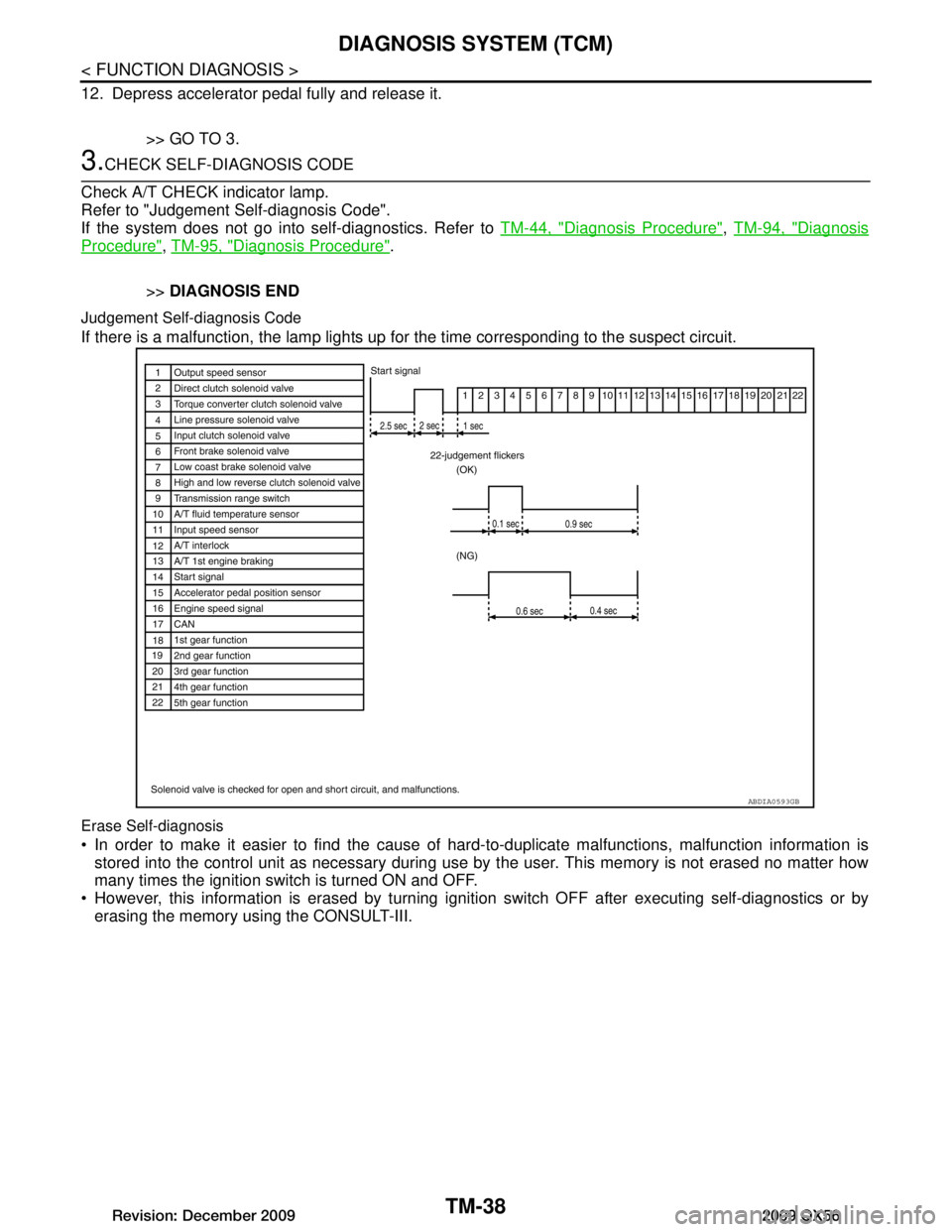
Judgement Self-diagnosis Code
If there is a malfunction, the lamp lights up fo r the time corresponding to the suspect circuit.
Erase Self-diagnosis
In order to make it easier to find the cause of hard-to-duplicate malfunctions, malfunction information is
stored into the control unit as necessary during use by the user. This memory is not erased no matter how
many times the ignition switch is turned ON and OFF.
However, this information is erased by turning igni tion switch OFF after executing self-diagnostics or by
erasing the memory using the CONSULT-III.
ABDIA0593GB
Revision: December 20092009 QX56
Page 3687 of 4171
U1000 CAN COMM CIRCUITTM-39
< COMPONENT DIAGNOSIS >
CEF
G H
I
J
K L
M A
B
TM
N
O P
COMPONENT DIAGNOSIS
U1000 CAN COMM CIRCUIT
DescriptionINFOID:0000000003771825
CAN (Controller Area Network) is a serial communication li ne for real time application. It is an on-vehicle mul-
tiplex communication line with high data communica tion speed and excellent malfunction detection ability.
Many electronic control units are equipped onto a vehicl e, and each control unit shares information and links
with other control units during operation (not independent ). In CAN communication, control units are con-
nected with 2 communication lines (CAN H line, CAN L li ne) allowing a high rate of information transmission
with less wiring. Each control unit transmits/recei ves data but selectively reads required data only.
On Board Diagnosis LogicINFOID:0000000003771826
This is an OBD-III self-diagnostic item.
Diagnostic trouble code “U1000” with CONSULT-III is detected when TCM cannot communicate to other
control units.
Possible CauseINFOID:0000000003771827
Harness or connectors
(CAN communication line is open or shorted.)
DTC Confirmation ProcedureINFOID:0000000003771828
NOTE:
If “DTC Confirmation Procedure” has been previously performed, always turn ignition switch “OFF”
and wait at least 10 seconds before performing the next test.
After the repair, perform the following procedure to confirm the malfunction is eliminated.
WITH CONSULT-III
1. Turn ignition switch “ON”. (Do not start engine.)
2. Select “DATA MONITOR” mode for “ENGINE” with CONSULT-III.
3. Start engine and wait for at least 6 seconds.
4. If DTC is detected, go to TM-39, "Diagnosis Procedure"
.
WITH GST
Follow the procedure “WITH CONSULT-III”.
Diagnosis ProcedureINFOID:0000000003771829
1.CHECK CAN COMMUNICATION CIRCUIT
With CONSULT-III1. Turn ignition switch “ON” and start engine.
2. Select “SELF-DIAG RESULTS” mode for “TRANSMISSION” with CONSULT-III.
Is any malfunction of the
“CAN COMM CIRCUIT” indicated?
YES >> Go to LAN section. Refer to LAN-14, "Trouble Diagnosis Flow Chart".
NO >> INSPECTION END
Revision: December 20092009 QX56
Page 3688 of 4171
TM-40
< COMPONENT DIAGNOSIS >
P0615 STARTER RELAY
P0615 STARTER RELAY
DescriptionINFOID:0000000003771830
TCM prohibits cranking other than at “P” or “N” position.
CONSULT-III Reference Value in Data Monitor ModeINFOID:0000000003771831
On Board Diagnosis LogicINFOID:0000000003771832
This is not an OBD-II self-diagnostic item.
Diagnostic trouble code “P0615” with CONSULT-III is det ected when starter relay is switched “ON” other
than at “P” or “N” position. (Or when sw itched “OFF” at “P” or “N” position).
Possible CauseINFOID:0000000003771833
Harness or connectors
[The starter relay and TCM circuit is open or shorted.]
Starter relay
DTC Confirmation ProcedureINFOID:0000000003771834
NOTE:
If “DTC Confirmation Procedure” has been previously performed, always turn ignition switch “OFF”
and wait at least 10 seconds before performing the next test.
After the repair, perform the following proc edure to confirm the malfunction is eliminated.
WITH CONSULT-III
1. Turn ignition switch “ON”. (Do not start engine.)
2. Select “DATA MONITOR” mode for “TRANSMISSION” with CONSULT-III.
3. Start engine.
4. Drive vehicle for at least 2 consecutive seconds.
5. If DTC is detected, go to TM-40, "Diagnosis Procedure"
.
Diagnosis ProcedureINFOID:0000000003771835
1.CHECK STARTER RELAY
With CONSULT-III
1. Turn ignition switch “ON”. (Do not start engine.)
2. Select “SELECTION FROM MENU” in “DATA MONI TOR” mode for “TRANSMISSION” with CONSULT-III
and check monitor “STARTER RELAY” ON/OFF.
Without CONSULT-III
Item name Condition Display value
STARTER RELAY Selector lever in “N”,“P” position. ON
Selector lever in other position. OFF
Item name Condition Display value
STARTER RELAY Selector lever in "N'', "P'' positions. ON
Selector lever in other positions. OFF
Revision: December 20092009 QX56
Page 3689 of 4171
P0615 STARTER RELAYTM-41
< COMPONENT DIAGNOSIS >
CEF
G H
I
J
K L
M A
B
TM
N
O P
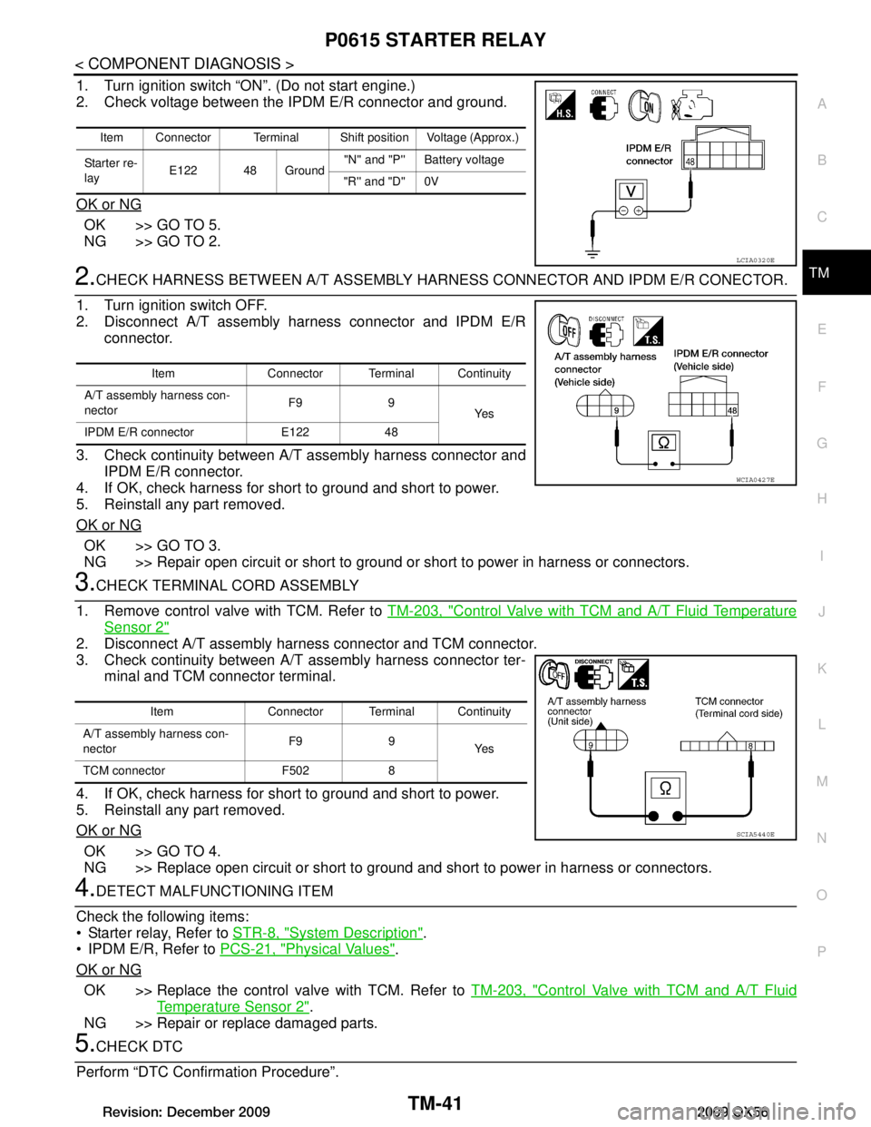
1. Turn ignition switch “ON”. (Do not start engine.)
2. Check voltage between the IPDM E/R connector and ground.
OK or NG
OK >> GO TO 5.
NG >> GO TO 2.
2.CHECK HARNESS BETWEEN A/T AS SEMBLY HARNESS CONNECTOR AND IPDM E/R CONECTOR.
1. Turn ignition switch OFF.
2. Disconnect A/T assembly harness connector and IPDM E/R connector.
3. Check continuity between A/T assembly harness connector and IPDM E/R connector.
4. If OK, check harness for short to ground and short to power.
5. Reinstall any part removed.
OK or NG
OK >> GO TO 3.
NG >> Repair open circuit or short to ground or short to power in harness or connectors.
3.CHECK TERMINAL CORD ASSEMBLY
1. Remove control valve with TCM. Refer to TM-203, "Control Valve with TCM and A/T Fluid Temperature
Sensor 2"
2. Disconnect A/T assembly harness connector and TCM connector.
3. Check continuity between A/T assembly harness connector ter-
minal and TCM connector terminal.
4. If OK, check harness for short to ground and short to power.
5. Reinstall any part removed.
OK or NG
OK >> GO TO 4.
NG >> Replace open circuit or short to ground and short to power in harness or connectors.
4.DETECT MALFUNCTIONING ITEM
Check the following items:
Starter relay, Refer to STR-8, "System Description"
.
IPDM E/R, Refer to PCS-21, "Physical Values"
.
OK or NG
OK >> Replace the control valve with TCM. Refer to TM-203, "Control Valve with TCM and A/T Fluid
Temperature Sensor 2".
NG >> Repair or replace damaged parts.
5.CHECK DTC
Perform “DTC Confirmation Procedure”.
Item Connector Terminal Shift position Voltage (Approx.)
Starter re-
lay E122 48 Ground "N'' and "P'' Battery voltage
"R'' and "D'' 0V
LCIA0320E
Item Connector Terminal Continuity
A/T assembly harness con-
nector F9 9
Ye s
IPDM E/R connector E122 48
WCIA0427E
Item Connector Terminal Continuity
A/T assembly harness con-
nector F9 9
Ye s
TCM connector F502 8
SCIA5440E
Revision: December 20092009 QX56