2009 INFINITI QX56 torque
[x] Cancel search: torquePage 2579 of 4171
![INFINITI QX56 2009 Factory Service Manual LAN-10
< FUNCTION DIAGNOSIS >[CAN FUNDAMENTAL]
TROUBLE DIAGNOSIS
Self-Diagnosis
INFOID:0000000003776437
CAN Diagnostic Support MonitorINFOID:0000000003776438
CONSULT-III and CAN diagnostic support mon INFINITI QX56 2009 Factory Service Manual LAN-10
< FUNCTION DIAGNOSIS >[CAN FUNDAMENTAL]
TROUBLE DIAGNOSIS
Self-Diagnosis
INFOID:0000000003776437
CAN Diagnostic Support MonitorINFOID:0000000003776438
CONSULT-III and CAN diagnostic support mon](/manual-img/42/57031/w960_57031-2578.png)
LAN-10
< FUNCTION DIAGNOSIS >[CAN FUNDAMENTAL]
TROUBLE DIAGNOSIS
Self-Diagnosis
INFOID:0000000003776437
CAN Diagnostic Support MonitorINFOID:0000000003776438
CONSULT-III and CAN diagnostic support monitor (on-boar d diagnosis function) are used for detecting root
cause.
MONITOR ITEM (CONSULT-III)
Unit name Symptom
ECM • Engine torque limiting is affected, and shift harshness increases.
• Engine speed drops.
BCM • Reverse warning chime does not sound.
• The front wiper moves under continuous operation mode even though the front
wiper switch being in the intermittent position.
• The room lamp does not turn ON.
• The engine does not start (if an error or malfunction occurs while turning the igni- tion switch OFF.)
• The steering lock does not release (if an error or malfunction occurs while turning the ignition switch OFF.)
EPS control unit The steering effort increases.
Combination meter • The tachometer and the speedometer do not move.
• Warning lamps turn ON.
• Indicator lamps do not turn ON.
ABS actuator and electric unit (control unit) Normal operation.
TCM No impact on operation.
IPDM E/R When the ignition switch is ON,
• The headlamps (Lo) turn ON.
• The cooling fan continues to rotate.
DTC
Self-diagnosis item
(CONSULT-III indication) DTC detection condition
Inspection/Action
U1000 CAN COMM CIRCUIT When ECM is not transmitting or receiving CAN
communication signal of OBD (emission-related
diagnosis) for 2 seconds or more.
Refer to LAN-13
.
When a control unit (except for ECM) is not
transmitting or receiving CAN communication
signal for 2 seconds or more.
U1001 CAN COMM CIRCUIT When ECM is not transmitting or receiving CAN
communication signal other than OBD (emis-
sion-related diagnosis) for 2 seconds or more.
U1002 SYSTEM COMM When a control unit is not transmitting or receiv-
ing CAN communication signal for 2 seconds or
less. Start the inspection. Re-
fer to the applicable sec-
tion of the indicated
control unit.
U1010 CONTROL UNIT(CAN) When an error is detected during the initial diag-
nosis for CAN controller of each control unit. Replace the control unit
indicating “U1010”.
Revision: December 20092009 QX56
Page 2664 of 4171
ENGINE OILLU-9
< ON-VEHICLE MAINTENANCE >
C
DE
F
G H
I
J
K L
M A
LU
NP
O
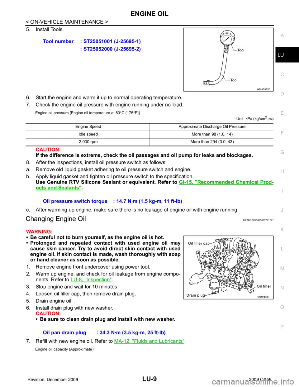
5. Install Tools.
6. Start the engine and warm it up to normal operating temperature.
7. Check the engine oil pressure with engine running under no-load.
Engine oil pressure [Engine oil temperature at 80
°C (175 °F)]
Unit: kPa (kg/cm2, psi)
CAUTION:
If the difference is extreme, check the oil passages and oil pump for leaks and blockages.
8. After the inspections, install oil pressure switch as follows:
a. Remove old liquid gasket adhering to oil pressure switch and engine.
b. Apply liquid gasket and tighten oil pressure switch to the specification. Use Genuine RTV Silicone Seal ant or equivalent. Refer to GI-15, "
Recommended Chemical Prod-
ucts and Sealants".
c. After warming up engine, make sure there is no leakage of engine oil with engine running.
Changing Engine OilINFOID:0000000003771271
WARNING:
• Be careful not to burn yourself, as the engine oil is hot.
• Prolonged and repeated contact with used engine oil may cause skin cancer. Try to avoid direct skin contact with used
engine oil. If skin contact is made, wash thoroughly with soap
or hand cleaner as soon as possible.
1. Remove engine front undercover using power tool.
2. Warm up engine, and check for oil leakage from engine compo- nents. Refer to LU-8, "
Inspection".
3. Stop engine and wait for 10 minutes.
4. Loosen oil filler cap, then remove drain plug.
5. Drain engine oil.
6. Install drain plug with new washer. CAUTION:
• Be sure to clean drain plug and install with new washer.
7. Refill with new engine oil. Refer to MA-12, "
Fluids and Lubricants".
Engine oil capacity (Approximate):
Tool number : ST25051001 (J-25695-1)
: ST25052000 (J-25695-2)
WBIA0571E
Engine Speed Approximate Discharge Oil Pressure
Idle speed More than 98 (1.0, 14)
2,000 rpm More than 294 (3.0, 43)
Oil pressure switch torque : 14.7 N·m (1.5 kg-m, 11 ft-lb)
Oil pan drain plug : 34.3 N·m (3.5 kg-m, 25 ft-lb)
KBIA2498E
Revision: December 20092009 QX56
Page 2698 of 4171
CHASSIS AND BODY MAINTENANCEMA-25
< ON-VEHICLE MAINTENANCE >
C
DE
F
G H
I
J
K L
M B
MA
N
O A
• To flush out the old A/T fluid from the transmission o
il coolers, pour new A/T fluid into the A/T fluid charg-
ing pipe with the engine idling and at the same time drain the old A/T fluid from the auxiliary transmis-
sion oil cooler hose return line.
• When the color of the A/T fluid coming out of the aux iliary transmission oil cooler hose return line is
about the same as the color of the new A/T fluid, flushing out the old A/T fluid is complete. The amount
of new A/T fluid used for flushing should be 30% to 50% increase of the specified capacity.
CAUTION:
• If Genuine NISSAN Matic S ATF is not available, Genuine NISSAN Matic J ATF may also be used.
• Using ATF fluid other than Genuine NISSAN Matic S ATF or Matic J ATF will cause deterioration
in driveability and A/T durability, and may damage the A/T, which is not covered by the warranty.
• When filling the transmission with A/T fluid, do not spill the A/T fluid on any heat generating
parts such as the exhaust parts.
• Do not reuse the drain plug gasket.
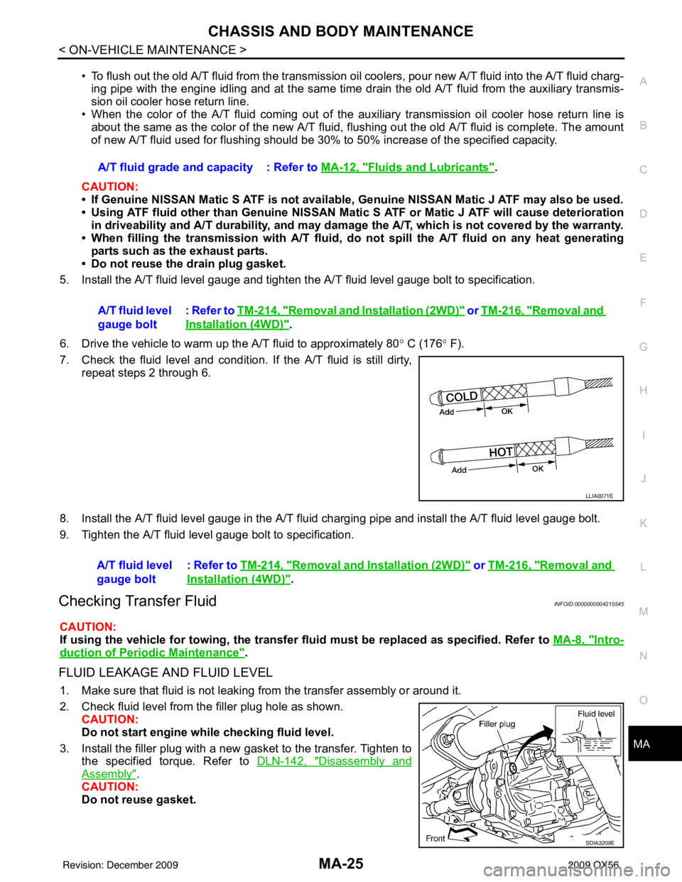
5. Install the A/T fluid level gauge and tighten t he A/T fluid level gauge bolt to specification.
6. Drive the vehicle to warm up the A/T fluid to approximately 80 ° C (176 ° F).
7. Check the fluid level and condition. If the A/T fluid is still dirty, repeat steps 2 through 6.
8. Install the A/T fluid level gauge in the A/T fluid charging pipe and install the A/T fluid level gauge bolt.
9. Tighten the A/T fluid level gauge bolt to specification.
Checking Transfer FluidINFOID:0000000004215545
CAUTION:
If using the vehicle for towing, the transfer fluid must be replaced as specified. Refer to MA-8, "
Intro-
duction of Periodic Maintenance".
FLUID LEAKAGE AND FLUID LEVEL
1. Make sure that fluid is not leaking from the transfer assembly or around it.
2. Check fluid level from the filler plug hole as shown.
CAUTION:
Do not start engine while checking fluid level.
3. Install the filler plug with a new gasket to the transfer. Tighten to the specified torque. Refer to DLN-142, "
Disassembly and
Assembly".
CAUTION:
Do not reuse gasket. A/T fluid grade and capacity : Refer to MA-12, "
Fluids and Lubricants".
A/T fluid level
gauge bolt : Refer to
TM-214, "
Removal and Installation (2WD)" or TM-216, "Removal and
Installation (4WD)".
LLIA0071E
A/T fluid level
gauge bolt : Refer to TM-214, "Removal and Installation (2WD)" or TM-216, "Removal and
Installation (4WD)".
SDIA3209E
Revision: December 20092009 QX56
Page 2699 of 4171
MA-26
< ON-VEHICLE MAINTENANCE >
CHASSIS AND BODY MAINTENANCE
Changing Transfer Fluid
INFOID:0000000004215546
CAUTION:
If using the vehicle for towing, the transfer fluid must be replaced as specified. Refer to MA-8, "
Intro-
duction of Periodic Maintenance".
DRAINING
1. Stop engine.
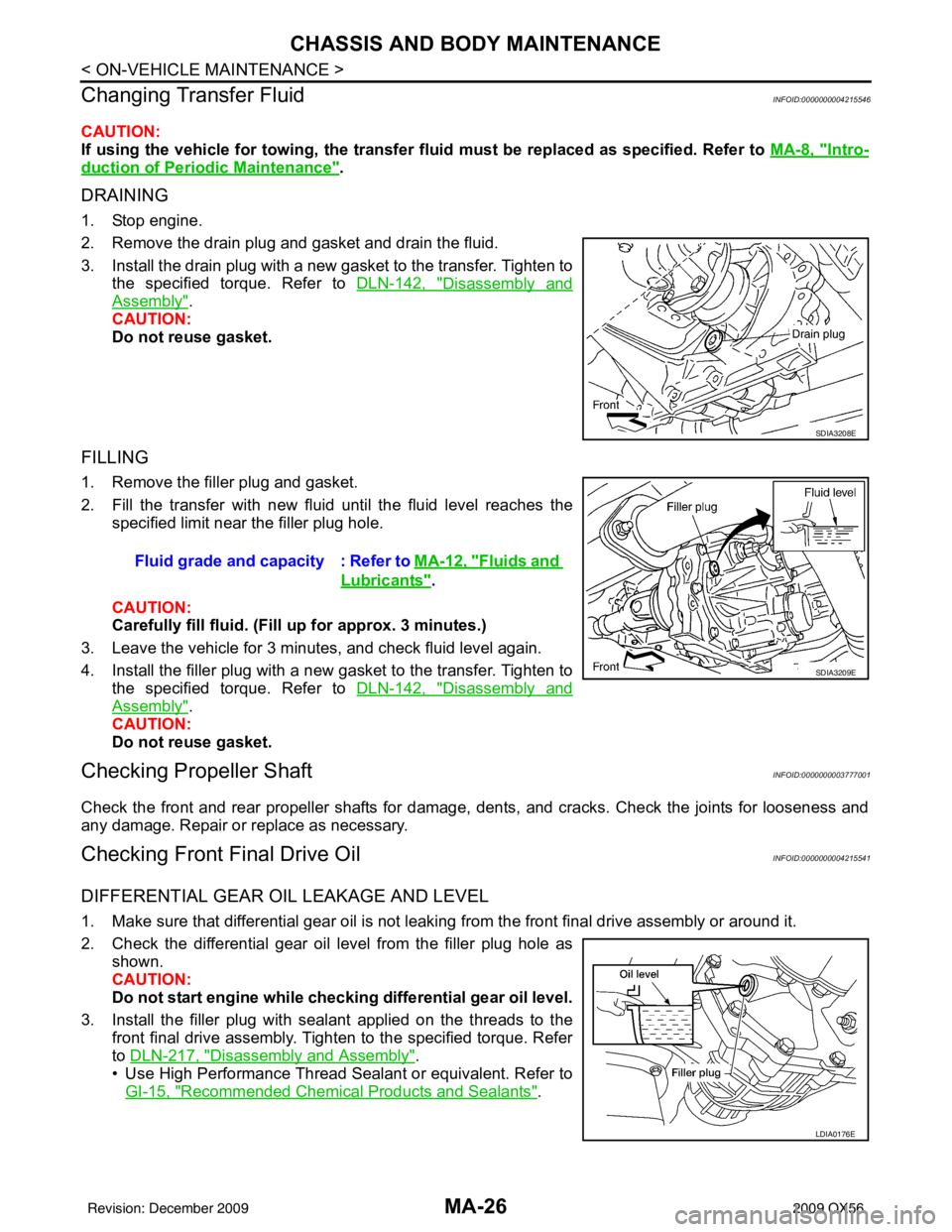
2. Remove the drain plug and gasket and drain the fluid.
3. Install the drain plug with a new gasket to the transfer. Tighten to
the specified torque. Refer to DLN-142, "
Disassembly and
Assembly".
CAUTION:
Do not reuse gasket.
FILLING
1. Remove the filler plug and gasket.
2. Fill the transfer with new fluid until the fluid level reaches the specified limit near the filler plug hole.
CAUTION:
Carefully fill fluid. (Fil l up for approx. 3 minutes.)
3. Leave the vehicle for 3 minutes, and check fluid level again.
4. Install the filler plug with a new gasket to the transfer. Tighten to the specified torque. Refer to DLN-142, "
Disassembly and
Assembly".
CAUTION:
Do not reuse gasket.
Checking Propeller ShaftINFOID:0000000003777001
Check the front and rear propeller shafts for damage, dents, and cracks. Check the joints for looseness and
any damage. Repair or replace as necessary.
Checking Front Final Drive OilINFOID:0000000004215541
DIFFERENTIAL GEAR OIL LEAKAGE AND LEVEL
1. Make sure that differential gear oil is not leaki ng from the front final drive assembly or around it.
2. Check the differential gear oil level from the filler plug hole as shown.
CAUTION:
Do not start engine while checki ng differential gear oil level.
3. Install the filler plug with sealant applied on the threads to the front final drive assembly. Tighten to the specified torque. Refer
to DLN-217, "
Disassembly and Assembly".
• Use High Performance Thread Sealant or equivalent. Refer to GI-15, "
Recommended Chemical Products and Sealants".
SDIA3208E
Fluid grade and capacity : Refer to MA-12, "Fluids and
Lubricants".
SDIA3209E
LDIA0176E
Revision: December 20092009 QX56
Page 2700 of 4171
CHASSIS AND BODY MAINTENANCEMA-27
< ON-VEHICLE MAINTENANCE >
C
DE
F
G H
I
J
K L
M B
MA
N
O A
Changing Front Final Drive OilINFOID:0000000004215542
DRAINING
1. Stop the engine.
2. Remove the drain plug from the front final drive assembly to drain the differential gear oil.
3. Install the drain plug with sealant applied on the thr
eads to the front final drive assembly. Tighten to the
specified torque. Refer to DLN-217, "
Disassembly and Assembly".
• Use High Performance Thread Sealant or equivalent. Refer to GI-15, "
Recommended Chemical Prod-
ucts and Sealants".
FILLING
1. Remove the filler plug from the front final drive assembly.
2. Fill the front final drive assembly with new differential gear oil
until the level reaches the specified level near the filler plug hole.
3. Install the filler plug with sealant applied on the threads to the front final drive assembly. Tighten to the specified torque. Refer
to DLN-217, "
Disassembly and Assembly".
• Use High Performance Thread Sealant or equivalent. Refer to
GI-15, "
Recommended Chemical Products and Sealants".
Checking Rear Final Drive OilINFOID:0000000004215543
OIL LEAKAGE AND OIL LEVEL
1. Make sure that differential gear oil is not leaking from the rear final drive assembly or around it.
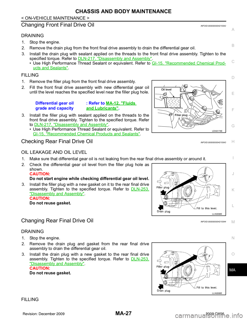
2. Check the differential gear oil level from the filler plug hole as shown.
CAUTION:
Do not start engine while checki ng differential gear oil level.
3. Install the filler plug with a new gasket on it to the rear final drive assembly. Tighten to the specified torque. Refer to DLN-253,
"Disassembly and Assembly".
CAUTION:
Do not reuse gasket.
Changing Rear Final Drive OilINFOID:0000000004215544
DRAINING
1. Stop the engine.
2. Remove the drain plug and gasket from the rear final drive assembly to drain the differential gear oil.
3. Install the drain plug with a new gasket to the rear final drive assembly. Tighten to the specified torque. Refer to DLN-253,
"Disassembly and Assembly".
CAUTION:
Do not reuse gasket.
FILLING
Differential gear oil
grade and capacity : Refer to
MA-12, "Fluids
and Lubricants".
LDIA0176E
LLIA0068E
LLIA0068E
Revision: December 20092009 QX56
Page 2701 of 4171
MA-28
< ON-VEHICLE MAINTENANCE >
CHASSIS AND BODY MAINTENANCE
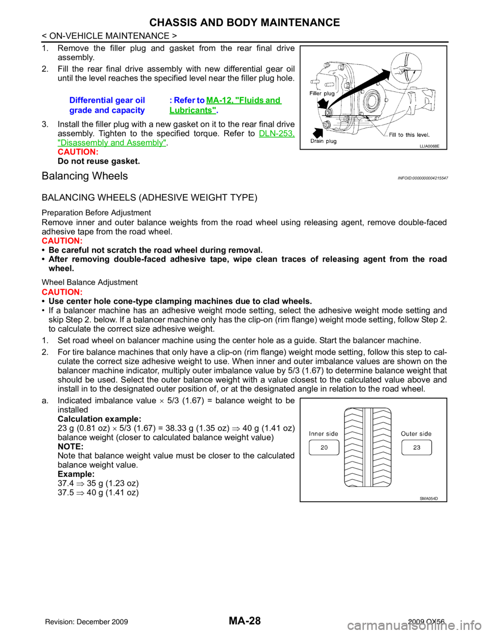
1. Remove the filler plug and gasket from the rear final driveassembly.
2. Fill the rear final drive assembly with new differential gear oil until the level reaches the specified level near the filler plug hole.
3. Install the filler plug with a new gasket on it to the rear final drive assembly. Tighten to the specified torque. Refer to DLN-253,
"Disassembly and Assembly".
CAUTION:
Do not reuse gasket.
Balancing WheelsINFOID:0000000004215547
BALANCING WHEELS (ADHESIVE WEIGHT TYPE)
Preparation Before Adjustment
Remove inner and outer balance weights from the road wheel using releasing agent, remove double-faced
adhesive tape from the road wheel.
CAUTION:
• Be careful not scratch the road wheel during removal.
• After removing double-faced adhesive tape, wipe clean traces of releasing agent from the road
wheel.
Wheel Balance Adjustment
CAUTION:
• Use center hole cone-type clamping machines due to clad wheels.
• If a balancer machine has an adhesive weight mode se tting, select the adhesive weight mode setting and
skip Step 2. below. If a balancer machine only has the clip-on (rim flange) weight mode setting, follow Step 2.
to calculate the correct size adhesive weight.
1. Set road wheel on balancer machine using the center hole as a guide. Start the balancer machine.
2. For tire balance machines that only have a clip-on (rim flange) weight mode setting, follow this step to cal- culate the correct size adhesive weight to use. When inner and outer imbalance values are shown on the
balancer machine indicator, multiply outer imbalance value by 5/3 (1.67) to determine balance weight that
should be used. Select the outer balance weight with a value closest to the calculated value above and
install in to the designated outer position of, or at the designated angle in relation to the road wheel.
a. Indicated imbalance value × 5/3 (1.67) = balance weight to be
installed
Calculation example:
23 g (0.81 oz) × 5/3 (1.67) = 38.33 g (1.35 oz) ⇒ 40 g (1.41 oz)
balance weight (closer to calculated balance weight value)
NOTE:
Note that balance weight value must be closer to the calculated
balance weight value.
Example:
37.4 ⇒ 35 g (1.23 oz)
37.5 ⇒ 40 g (1.41 oz)
Differential gear oil
grade and capacity
: Refer to MA-12, "
Fluids and
Lubricants".
LLIA0068E
SMA054D
Revision: December 20092009 QX56
Page 2702 of 4171
CHASSIS AND BODY MAINTENANCEMA-29
< ON-VEHICLE MAINTENANCE >
C
DE
F
G H
I
J
K L
M B
MA
N
O A
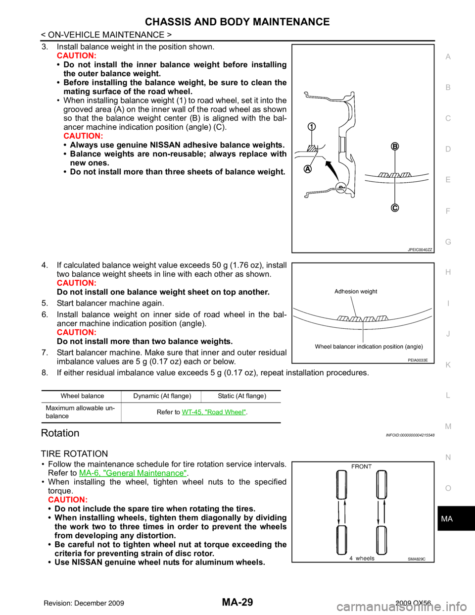
3. Install balance weight in the position shown.
CAUTION:
• Do not install the inner bala nce weight before installing
the outer balance weight.
• Before installing the balance weight, be sure to clean the mating surface of the road wheel.
• When installing balance weight (1) to road wheel, set it into the grooved area (A) on the inner wall of the road wheel as shown
so that the balance weight cent er (B) is aligned with the bal-
ancer machine indication position (angle) (C).
CAUTION:
• Always use genuine NISSAN adhesive balance weights.
• Balance weights are non-re usable; always replace with
new ones.
• Do not install more than th ree sheets of balance weight.
4. If calculated balance weight value exceeds 50 g (1.76 oz), install two balance weight sheets in line with each other as shown.
CAUTION:
Do not install one balance weight sheet on top another.
5. Start balancer machine again.
6. Install balance weight on inner side of road wheel in the bal- ancer machine indication position (angle).
CAUTION:
Do not install more than two balance weights.
7. Start balancer machine. Make sure that inner and outer residual imbalance values are 5 g (0.17 oz) each or below.
8. If either residual imbalance value exceeds 5 g (0.17 oz), repeat installation procedures.
RotationINFOID:0000000004215548
TIRE ROTATION
• Follow the maintenance schedule for tire rotation service intervals.
Refer to MA-6, "
General Maintenance".
• When installing the wheel, tighten wheel nuts to the specified
torque.
CAUTION:
• Do not include the spare tire when rotating the tires.
• When installing wheels, tighte n them diagonally by dividing
the work two to three times in order to prevent the wheels
from developing any distortion.
• Be careful not to tighten wh eel nut at torque exceeding the
criteria for preventing strain of disc rotor.
• Use NISSAN genuine wheel nuts for aluminum wheels.
JPEIC0040ZZ
Wheel balance Dynamic (At flange) Static (At flange)
Maximum allowable un-
balance Refer to WT-45, "
Road Wheel".
PEIA0033E
SMA829C
Revision: December 20092009 QX56
Page 2703 of 4171
MA-30
< ON-VEHICLE MAINTENANCE >
CHASSIS AND BODY MAINTENANCE
Checking Brake Fluid Level and Leaks
INFOID:0000000003777006
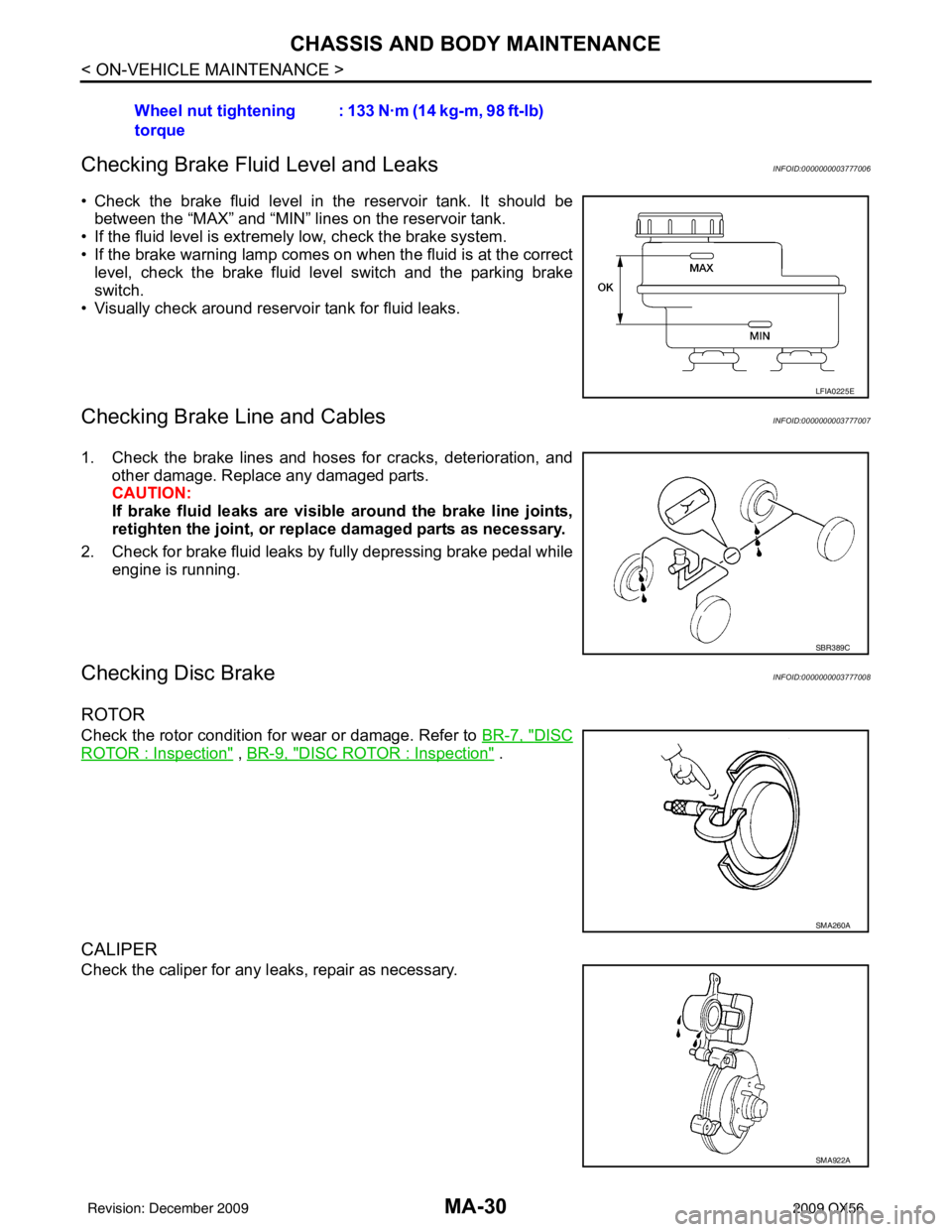
• Check the brake fluid level in the reservoir tank. It should be between the “MAX” and “MIN” lines on the reservoir tank.
• If the fluid level is extremely low, check the brake system.
• If the brake warning lamp comes on when the fluid is at the correct level, check the brake fluid level switch and the parking brake
switch.
• Visually check around reservoir tank for fluid leaks.
Checking Brake Line and CablesINFOID:0000000003777007
1. Check the brake lines and hoses for cracks, deterioration, and other damage. Replace any damaged parts.
CAUTION:
If brake fluid leaks are visible around the brake line joints,
retighten the joint, or replace damaged parts as necessary.
2. Check for brake fluid leaks by fully depressing brake pedal while engine is running.
Checking Disc BrakeINFOID:0000000003777008
ROTOR
Check the rotor condition for wear or damage. Refer to BR-7, "DISC
ROTOR : Inspection" , BR-9, "DISC ROTOR : Inspection" .
CALIPER
Check the caliper for any l eaks, repair as necessary.
Wheel nut tightening
torque
: 133 N·m (14 kg-m, 98 ft-lb)
LFIA0225E
SBR389C
SMA260A
SMA922A
Revision: December 20092009 QX56