2009 INFINITI QX56 fuse
[x] Cancel search: fusePage 2372 of 4171
![INFINITI QX56 2009 Factory Service Manual BLOWER MOTOR CONTROL SYSTEMHAC-59
< COMPONENT DIAGNOSIS > [AUTOMATIC AIR CONDITIONER]
C
D
E
F
G H
J
K L
M A
B
HAC
N
O P
1. Turn ignition switch OFF.
2. Check continuity between rear air control (front INFINITI QX56 2009 Factory Service Manual BLOWER MOTOR CONTROL SYSTEMHAC-59
< COMPONENT DIAGNOSIS > [AUTOMATIC AIR CONDITIONER]
C
D
E
F
G H
J
K L
M A
B
HAC
N
O P
1. Turn ignition switch OFF.
2. Check continuity between rear air control (front](/manual-img/42/57031/w960_57031-2371.png)
BLOWER MOTOR CONTROL SYSTEMHAC-59
< COMPONENT DIAGNOSIS > [AUTOMATIC AIR CONDITIONER]
C
D
E
F
G H
J
K L
M A
B
HAC
N
O P
1. Turn ignition switch OFF.
2. Check continuity between rear air control (front) harness con- nector R108 terminal 6 and ground.
Is the inspection result normal?
YES >> GO TO 5.
NO >> Repair harness or connector.
5.CHECK REAR AIR CONTROL (FRO NT) LIN BUS CIRCUIT FOR OPEN
1. Disconnect A/C auto amp. connector.
2. Check continuity between A/C auto amp. harness connector M50 (A) terminal 48 and rear air control (front) harness connec-
tor R108 (B) terminal 5.
Is the inspection result normal?
YES >> Replace A/C auto amp. Refer to VTL-7, "Removal and
Installation".
NO >> Repair harness or connector.
6.REPLACE FUSE
1. Replace fuse.
2. Activate the rear blower motor.
Does the fuse blow?
YES >> GO TO 7.
NO >> Inspection End.
7.CHECK REAR AIR CONTROL (FRONT) POWER SUPPLY CIRCUIT FOR SHORT
1. Turn ignition switch OFF.
2. Disconnect rear air control (front), (rear), and A/C auto amp. connectors.
3. Check continuity between rear air control (front) harness con- nector R108 terminal 1 and ground.
Is the inspection result normal?
YES >> Repair harness or connector for a short.
NO >> System OK.
Rear Air Control (Rea r) Diagnosis Procedure #2INFOID:0000000003775363
REAR AIR CONTROL (REAR) INOPERATIVE
1.CHECK REAR AIR CONTROL (REAR) POWER SUPPLYContinuity should exist.
AWIIA0184ZZ
Continuity should exist.
AWIIA0185ZZ
1 - Ground
: Continuity should not exist.
AWIIA0186ZZ
Revision: December 20092009 QX56
Page 2387 of 4171
![INFINITI QX56 2009 Factory Service Manual HAC-74
< COMPONENT DIAGNOSIS >[AUTOMATIC AIR CONDITIONER]
MAGNET CLUTCH
NO >> Check 10A fuse (No. 42, located in IPDM E/R), and GO TO 3.
3.CHECK CIRCUIT CONTINUITY BETW
EEN IPDM E/R AND COMPRESSOR
1. INFINITI QX56 2009 Factory Service Manual HAC-74
< COMPONENT DIAGNOSIS >[AUTOMATIC AIR CONDITIONER]
MAGNET CLUTCH
NO >> Check 10A fuse (No. 42, located in IPDM E/R), and GO TO 3.
3.CHECK CIRCUIT CONTINUITY BETW
EEN IPDM E/R AND COMPRESSOR
1.](/manual-img/42/57031/w960_57031-2386.png)
HAC-74
< COMPONENT DIAGNOSIS >[AUTOMATIC AIR CONDITIONER]
MAGNET CLUTCH
NO >> Check 10A fuse (No. 42, located in IPDM E/R), and GO TO 3.
3.CHECK CIRCUIT CONTINUITY BETW
EEN IPDM E/R AND COMPRESSOR
1. Turn ignition switch OFF.
2. Disconnect IPDM E/R connector and compressor (magnet clutch) connector.
3. Check continuity between IPDM E/R harness connector E119
terminal 11 and A/C compressor harness connector F3 terminal
1.
Is the inspection result normal?
YES >> GO TO 4.
NO >> Repair harness or connector.
4.CHECK MAGNET CLUTCH CIRCUIT
Check for operation sound when applying battery voltage direct cur-
rent to terminal.
Is the inspection result normal?
YES >> Replace IPDM E/R. Refer to PCS-34, "Removal and
Installation of IPDM E/R".
NO >> Replace magnet clutch. Refer to HA-32, "
Removal and
Installation for Compressor Clutch".
5.CHECK BCM INPUT (COMPRESSOR ON) SIGNAL
Check compressor ON/OFF signal. Refer to HAC-20, "
CONSULT-III Function (HVAC)".
Is the inspection result normal?
YES >> GO TO 8.
NO >> GO TO 6.
6.CHECK CIRCUIT CONTINUITY BETW EEN BCM AND A/C AUTO AMP.
1. Turn ignition switch OFF.
2. Disconnect BCM connector and A/C auto amp. connector.
3. Check continuity between BCM harness connector M18 (A) ter- minal 27 and A/C auto amp. harness connector M49 (B) terminal
4.
Is the inspection result normal?
YES >> GO TO 7.
NO >> Repair harness or connector.
7.CHECK VOLTAGE FOR A/C AUTO AMP. (A/C COMPRESSOR ON SIGNAL)
11 – 1
: Continuity should exist.
WJIA0560E
SJIA0197E
A/C SW ON: COMP ON SIG ON
A/C SW OFF : COMP ON SIG OFF
27 - 4 Continuity should exist.
AWIIA0199ZZ
Revision: December 20092009 QX56
Page 2403 of 4171
![INFINITI QX56 2009 Factory Service Manual HAC-90
< COMPONENT DIAGNOSIS >[AUTOMATIC AIR CONDITIONER]
POWER SUPPLY AND GROUND
CIRCUIT FOR CONTROLLER
Check main power supply and ground circuit. Refer to HAC-90, "A/C Auto Amp Power and Ground D INFINITI QX56 2009 Factory Service Manual HAC-90
< COMPONENT DIAGNOSIS >[AUTOMATIC AIR CONDITIONER]
POWER SUPPLY AND GROUND
CIRCUIT FOR CONTROLLER
Check main power supply and ground circuit. Refer to HAC-90, "A/C Auto Amp Power and Ground D](/manual-img/42/57031/w960_57031-2402.png)
HAC-90
< COMPONENT DIAGNOSIS >[AUTOMATIC AIR CONDITIONER]
POWER SUPPLY AND GROUND
CIRCUIT FOR CONTROLLER
Check main power supply and ground circuit. Refer to HAC-90, "A/C Auto Amp Power and Ground Diagnosis
Procedure".
Is the inspection result normal?
YES >> System OK.
NO >> Replace A/C auto amp. Refer to VTL-7, "
Removal and Installation".
A/C Auto Amp Power and Ground Diagnosis ProcedureINFOID:0000000003775387
DIAGNOSTIC PROCEDURE FOR A/C SYSTEM
SYMPTOM: A/C system does not come on.
1. CHECK POWER SUPPLY CIRCUITS FOR A/C AUTO AMP.
1. Turn ignition switch ON.
2. Check voltage between A/C auto amp. harness connector M49 (B) terminal 15 and M50 (A) terminal 27, and ground.
Is the inspection result normal?
YES >> GO TO 2.
NO >> Check 10A fuses [Nos. 8 and 19, located in the fuse block (J/B)]. Refer to PG-72, "
Terminal
Arrangement".
• If fuses are OK, check harness for open circuit. Repair or replace as necessary.
• If fuses are NG, replace fuse and check harness fo r short circuit. Repair or replace as neces-
sary.
2. CHECK GROUND CIRCUIT FOR A/C AUTO AMP.
1. Turn ignition switch OFF.
2. Disconnect A/C auto amp. connectors.
3. Check continuity between A/C auto amp. harness connector M50 terminal 36 and ground.
Is the inspection result normal?
OK >> Replace A/C auto amp. Refer to VTL-7, "Removal and
Installation".
NG >> Repair harness or connector.
AWIIA0212GB
Terminals Ignition switch position
(+)
(-) OFF ACC ON
A/C auto
amp. con- nector Te r m i n a l N o .
M49 15 GroundApprox. 0V Approx. 0V
Battery
voltage
M50 27 Battery
voltage Battery
voltage Battery
voltage
AWIIA1073ZZ
36 - Ground : Continuity should exist.
AWIIA0214ZZ
Revision: December 20092009 QX56
Page 2458 of 4171

INL-14
< COMPONENT DIAGNOSIS >
POWER SUPPLY AND GROUND CIRCUIT
COMPONENT DIAGNOSIS
POWER SUPPLY AND GROUND CIRCUIT
BCM
BCM : Diagnosis ProcedureINFOID:0000000004109550
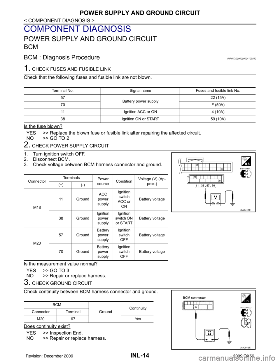
1. CHECK FUSES AND FUSIBLE LINK
Check that the following fuses and fusible link are not blown.
Is the fuse blown?
YES >> Replace the blown fuse or fusible link after repairing the affected circuit.
NO >> GO TO 2
2. CHECK POWER SUPPLY CIRCUIT
1. Turn ignition switch OFF.
2. Disconnect BCM.
3. Check voltage between BCM harness connector and ground.
Is the measurement value normal?
YES >> GO TO 3
NO >> Repair or replace harness.
3. CHECK GROUND CIRCUIT
Check continuity between BCM harness connector and ground.
Does continuity exist?
YES >> Inspection End.
NO >> Repair or replace harness.
Terminal No. Signal nameFuses and fusible link No.
57 Battery power supply 22 (15A)
70 F (50A)
11 Ignition ACC or ON 4 (10A)
38 Ignition ON or START 59 (10A)
ConnectorTe r m i n a l s
Power
source Condition Voltage (V) (Ap-
prox.)
(+) (-)
M18 11 Ground
ACC
power
supply Ignition
switch
ACC or ON Battery voltage
38 Ground Ignition
power
supply Ignition
switch ON
or START Battery voltage
M20 57 Ground
Battery
power
supply Ignition
switch OFF Battery voltage
70 Ground Battery
power
supply Ignition
switch OFF Battery voltage
LIIA2415E
BCM
GroundContinuity
Connector Terminal
M20 67 Yes
LIIA0915E
Revision: December 20092009 QX56
Page 2557 of 4171

INSTRUMENT PANEL ASSEMBLYIP-13
< ON-VEHICLE REPAIR >
C
DE
F
G H
I
K L
M A
B
IP
N
O P
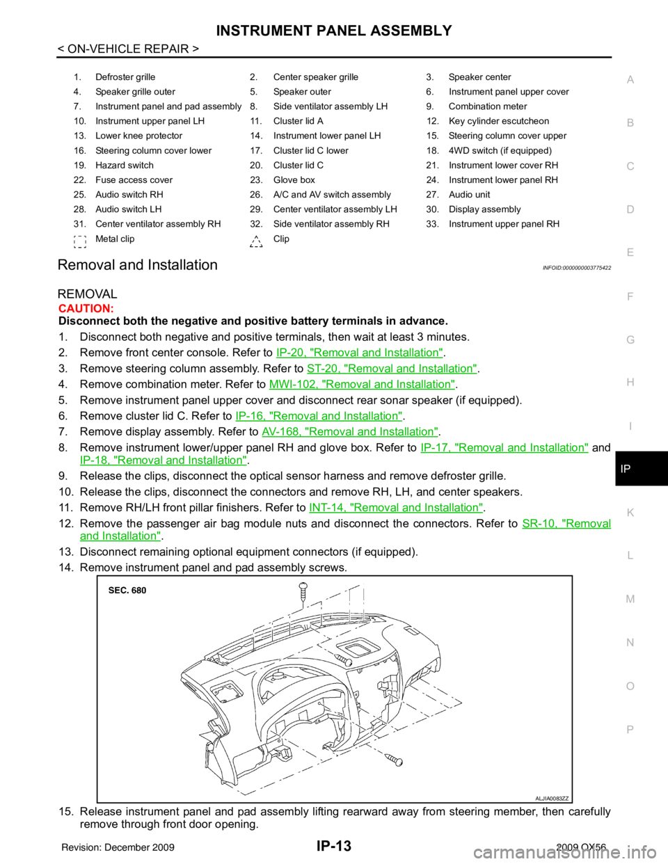
Removal and InstallationINFOID:0000000003775422
REMOVAL
CAUTION:
Disconnect both the negative and positive battery terminals in advance.
1. Disconnect both negative and positive terminal s, then wait at least 3 minutes.
2. Remove front center console. Refer to IP-20, "
Removal and Installation".
3. Remove steering column assembly. Refer to ST-20, "
Removal and Installation".
4. Remove combination meter. Refer to MWI-102, "
Removal and Installation".
5. Remove instrument panel upper cover and disconnect rear sonar speaker (if equipped).
6. Remove cluster lid C. Refer to IP-16, "
Removal and Installation".
7. Remove display assembly. Refer to AV-168, "
Removal and Installation".
8. Remove instrument lower/upper panel RH and glove box. Refer to IP-17, "
Removal and Installation" and
IP-18, "
Removal and Installation".
9. Release the clips, disconnect the optical sensor harness and remove defroster grille.
10. Release the clips, disconnect the connectors and remove RH, LH, and center speakers.
11. Remove RH/LH front pillar finishers. Refer to INT-14, "
Removal and Installation".
12. Remove the passenger air bag module nuts and disconnect the connectors. Refer to SR-10, "
Removal
and Installation".
13. Disconnect remaining optional equipment connectors (if equipped).
14. Remove instrument panel and pad assembly screws.
15. Release instrument panel and pad assembly lifting rearward away from steering member, then carefully remove through front door opening.
1. Defroster grille 2. Center speaker grille3. Speaker center
4. Speaker grille outer 5. Speaker outer6. Instrument panel upper cover
7. Instrument panel and pad assembly 8. Side ventilator assembly LH 9. Combination meter
10. Instrument upper panel LH 11. Cluster lid A 12. Key cylinder escutcheon
13. Lower knee protector 14. Instrument lower panel LH 15. Steering column cover upper
16. Steering column cover lower 17. Cluster lid C lower 18. 4WD switch (if equipped)
19. Hazard switch 20. Cluster lid C21. Instrument lower cover RH
22. Fuse access cover 23. Glove box 24. Instrument lower panel RH
25. Audio switch RH 26. A/C and AV switch assembly 27. Audio unit
28. Audio switch LH 29. Center ventilator assembly LH 30. Display assembly
31. Center ventilator assembly RH 32. Side ventilator assembly RH 33. Instrument upper panel RH Metal clip Clip
ALJIA0083ZZ
Revision: December 20092009 QX56
Page 2561 of 4171

INSTRUMENT LOWER PANEL RH AND GLOVE BOXIP-17
< ON-VEHICLE REPAIR >
C
DE
F
G H
I
K L
M A
B
IP
N
O P
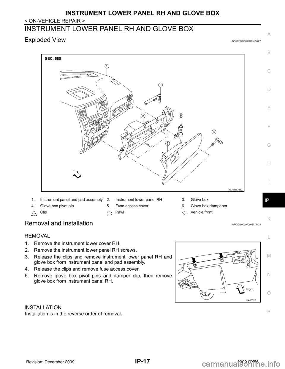
INSTRUMENT LOWER PANE L RH AND GLOVE BOX
Exploded ViewINFOID:0000000003775427
Removal and InstallationINFOID:0000000003775428
REMOVAL
1. Remove the instrument lower cover RH.
2. Remove the instrument lower panel RH screws.
3. Release the clips and remove instrument lower panel RH and
glove box from instrument panel and pad assembly.
4. Release the clips and remove fuse access cover.
5. Remove glove box pivot pins and damper clip, then remove glove box from instrument panel RH.
INSTALLATION
Installation is in the reverse order of removal.
1. Instrument panel and pad assembly 2. Instrument lower panel RH 3. Glove box
4. Glove box pivot pin 5. Fuse access cover6. Glove box dampener
Clip PawlVehicle front
ALJIA0533ZZ
LLIA0072E
Revision: December 20092009 QX56
Page 2576 of 4171
![INFINITI QX56 2009 Factory Service Manual LAN
TROUBLE DIAGNOSISLAN-7
< FUNCTION DIAGNOSIS > [CAN FUNDAMENTAL]
C
D
E
F
G H
I
J
K L
B A
O P
N
TROUBLE DIAGNOSIS
Condition of Error DetectionINFOID:0000000003776435
“U1000” or “U1001” is in INFINITI QX56 2009 Factory Service Manual LAN
TROUBLE DIAGNOSISLAN-7
< FUNCTION DIAGNOSIS > [CAN FUNDAMENTAL]
C
D
E
F
G H
I
J
K L
B A
O P
N
TROUBLE DIAGNOSIS
Condition of Error DetectionINFOID:0000000003776435
“U1000” or “U1001” is in](/manual-img/42/57031/w960_57031-2575.png)
LAN
TROUBLE DIAGNOSISLAN-7
< FUNCTION DIAGNOSIS > [CAN FUNDAMENTAL]
C
D
E
F
G H
I
J
K L
B A
O P
N
TROUBLE DIAGNOSIS
Condition of Error DetectionINFOID:0000000003776435
“U1000” or “U1001” is indicated on SELF-DIAG RESULTS on CONSULT-III if CAN communication signal is
not transmitted or received between units for 2 seconds or more.
CAN COMMUNICATION SYSTEM ERROR
• CAN communication line open (CAN-H, CAN-L, or both)
• CAN communication line short (ground, betw
een CAN communication lines, other harnesses)
• Error of CAN communication control circuit of the unit connected to CAN communication line
WHEN “U1000” OR “U1001” IS INDICATED EV EN THOUGH CAN COMMUNICATION SYSTEM IS
NORMAL
• Removal/installation of parts: Error may be detec ted when removing and installing CAN communication unit
and related parts while turning the ignition switch ON. (A DTC except for CAN communication may be
detected.)
• Fuse blown out (removed): CAN communication of the unit may cease.
• Voltage drop: Error may be detected if voltage drops due to discharged battery when turning the ignition
switch ON (Depending on the control unit which carries out CAN communication).
• Error may be detected if the power supply circuit of the control unit, which carries out CAN communication,
malfunctions (Depending on the control unit which carries out CAN communication).
• Error may be detected if reprogramming is not completed normally.
NOTE:
CAN communication system is normal if “U1000” or “U 1001” is indicated on SELF-DIAG RESULTS of CON-
SULT-III under the above conditions. Erase the memory of the self-diagnosis of each unit.
Symptom When Error Occurs in CAN Communication SystemINFOID:0000000003776436
In CAN communication system, multiple units mutually transmit and receive signals. Each unit cannot transmit
and receive signals if any error occurs on CAN communicati on line. Under this condition, multiple control units
related to the root cause malfunction or go into fail-safe mode.
ERROR EXAMPLE
NOTE:
• Each vehicle differs in symptom of each unit under fail-safe mode and CAN communication line wiring.
• Refer to LAN-36, "
Abbreviation List" for the unit abbreviation.
Example: TCM branch line open circuit
SKIB8738E
Unit name Symptom
ECM Engine torque limiting is affected, and shift harshness increases.
BCM Reverse warning chime does not sound.
Revision: December 20092009 QX56
Page 2655 of 4171
![INFINITI QX56 2009 Factory Service Manual LAN-86
< COMPONENT DIAGNOSIS >[CAN]
CAN COMMUNICATION CIRCUIT
Inspection result
Reproduced>>GO TO 6.
Non-reproduced>>Start the diagnosis again. Follow
the trouble diagnosis procedure when past error INFINITI QX56 2009 Factory Service Manual LAN-86
< COMPONENT DIAGNOSIS >[CAN]
CAN COMMUNICATION CIRCUIT
Inspection result
Reproduced>>GO TO 6.
Non-reproduced>>Start the diagnosis again. Follow
the trouble diagnosis procedure when past error](/manual-img/42/57031/w960_57031-2654.png)
LAN-86
< COMPONENT DIAGNOSIS >[CAN]
CAN COMMUNICATION CIRCUIT
Inspection result
Reproduced>>GO TO 6.
Non-reproduced>>Start the diagnosis again. Follow
the trouble diagnosis procedure when past error is
detected.
6.CHECK UNIT REPRODUCTION
Perform the reproduction test as per the following procedure for each unit.
1. Turn the ignition switch OFF.
2. Disconnect the battery cable from the negative terminal.
3. Disconnect one of the unit connectors of CAN communication system. NOTE:
ECM and IPDM E/R have a termination circuit. Check other units first.
4. Connect the battery cable to the negative terminal. Check if the symptoms described in the “Symptom
(Results from interview with customer)” are reproduced.
NOTE:
Although unit-related error symptoms occur, do not confuse them with other symptoms.
Inspection result
Reproduced>>Connect the connector. Check other units as per the above procedure.
Non-reproduced>>Replace the unit whose connector was disconnected.
Revision: December 20092009 QX56