2009 Hyundai Santa Fe headlight aiming
[x] Cancel search: headlight aimingPage 208 of 269

Engine Compartment .................................................... 6-2
General Checks ........................................................... 6-5
Maintenance Precautions ............................................. 6-6
Checking the Engine Oil .............................................. 6-6
Checking the Engine Coolant ...................................... 6-9
Changing the Air Cleaner Filter ...................................6-11
Checking the Transaxle Fluid (Automatic) .................6-15
Checking the Brakes .................................................. 6-17
Air Conditioning Care .................................................. 6-19
Changing the Climate Control Air Filter .. ....................6-19
Checking and Replacing Fuses ..................................6-21
Checking the Battery .................................................. 6-24
Power Steering Fluid Level ......................................... 6-26
Removal of Water from the Fuel Filter ........................6-27
Headlight Aiming Adjustment ...................................... 6-28
Replacement of Light Bulbs ........................................6-29
Bulb Wattage ............................................................... 6-37
Fuse Panel D escription ............................................... 6-38
DO-IT-YOURSELF MAINTENANCE
6
6
CM-aust-6.p65
5/19/2008, 6:37 PM
1
Page 235 of 269

6DO-IT-YOURSELF MAINTENANCE
28
OCM055007L
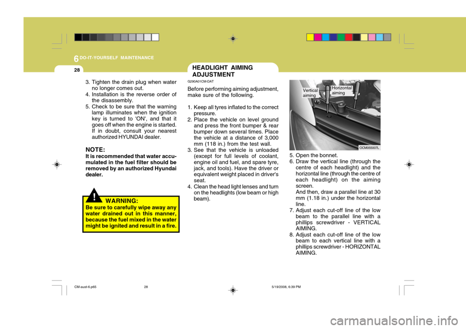
5. Open the bonnet.
6. Draw the vertical line (through the centre of each headlight) and thehorizontal line (through the centre of each headlight) on the aiming screen.And then, draw a parallel line at 30mm (1.18 in.) under the horizontalline.
7. Adjust each cut-off line of the low
beam to the parallel line with aphillips screwdriver - VERTICAL AIMING.
8. Adjust each cut-off line of the low beam to each vertical line with a phillips screwdriver - HORIZONTALAIMING.
Vertical aimingHorizontal aiming
HEADLIGHT AIMING ADJUSTMENT
G290A01CM-DAT Before performing aiming adjustment, make sure of the following.
1. Keep all tyres inflated to the correct pressure.
2. Place the vehicle on level ground and press the front bumper & rear bumper down several times. Placethe vehicle at a distance of 3,000 mm (118 in.) from the test wall.
3. See that the vehicle is unloaded (except for full levels of coolant, engine oil and fuel, and spare tyre,jack, and tools). Have the driver or equivalent weight placed in driver's seat.
4. Clean the head light lenses and turn on the headlights (low beam or highbeam).
!WARNING:
Be sure to carefully wipe away any water drained out in this manner, because the fuel mixed in the watermight be ignited and result in a fire.
3. Tighten the drain plug when water
no longer comes out.
4. Installation is the reverse order of the disassembly.
5. Check to be sure that the warning lamp illuminates when the ignitionkey is turned to 'ON', and that itgoes off when the engine is started.If in doubt, consult your nearestauthorized HYUNDAI dealer.
NOTE: It is recommended that water accu- mulated in the fuel filter should be removed by an authorized Hyundai dealer.
CM-aust-6.p65 5/19/2008, 6:39 PM
28
Page 236 of 269

6
DO-IT-YOURSELF MAINTENANCE
29
G290B01CM-DAT
Adjustment After Headlight Assembly Replacement
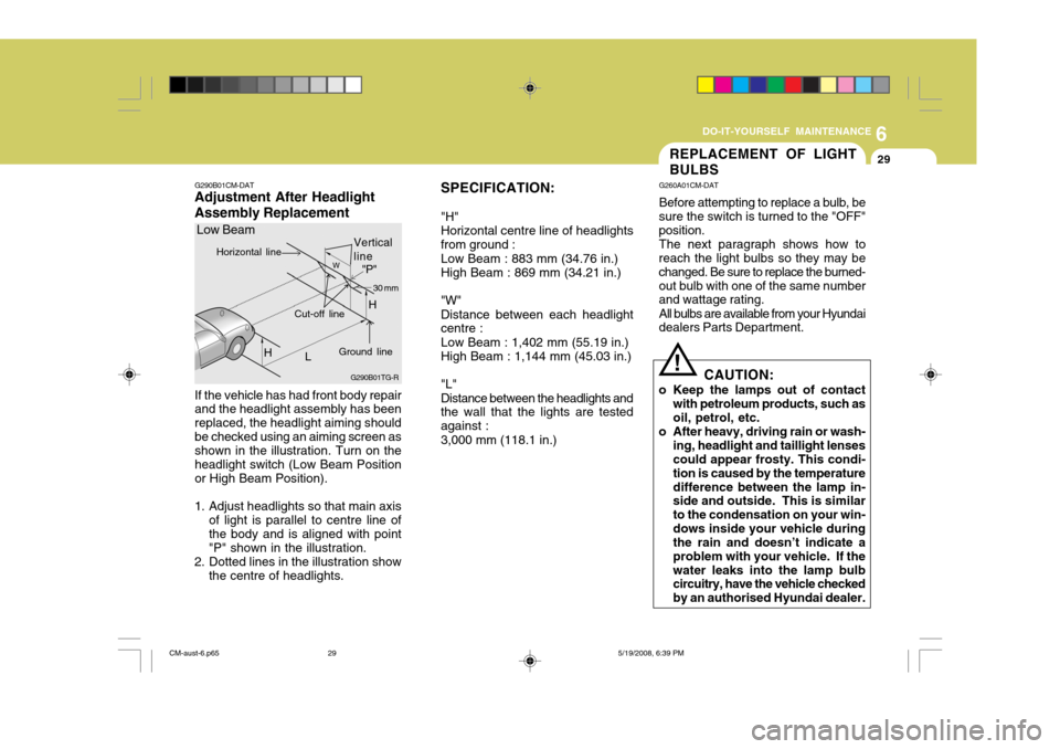
If the vehicle has had front body repair and the headlight assembly has been replaced, the headlight aiming shouldbe checked using an aiming screen as shown in the illustration. Turn on the headlight switch (Low Beam Positionor High Beam Position).
1. Adjust headlights so that main axis of light is parallel to centre line ofthe body and is aligned with point"P" shown in the illustration.
2. Dotted lines in the illustration show the centre of headlights. SPECIFICATION: "H" Horizontal centre line of headlightsfrom ground : Low Beam : 883 mm (34.76 in.) High Beam : 869 mm (34.21 in.) "W" Distance between each headlight centre : Low Beam : 1,402 mm (55.19 in.) High Beam : 1,144 mm (45.03 in.) "L" Distance between the headlights and the wall that the lights are tested against : 3,000 mm (118.1 in.)
G290B01TG-R
Low Beam
LW
H Cut-off line
"P"
Horizontal line
Ground line 30 mm
Vertical line
H
REPLACEMENT OF LIGHT BULBS
G260A01CM-DAT Before attempting to replace a bulb, be
sure the switch is turned to the "OFF" position.
The next paragraph shows how to
reach the light bulbs so they may bechanged. Be sure to replace the burned-out bulb with one of the same number and wattage rating.
All bulbs are available from your Hyundai
dealers Parts Department.
CAUTION:
o Keep the lamps out of contact with petroleum products, such asoil, petrol, etc.
o After heavy, driving rain or wash- ing, headlight and taillight lensescould appear frosty. This condi- tion is caused by the temperaturedifference between the lamp in- side and outside. This is similar to the condensation on your win-dows inside your vehicle during the rain and doesn’t indicate a problem with your vehicle. If thewater leaks into the lamp bulb circuitry, have the vehicle checked by an authorised Hyundai dealer.
!
CM-aust-6.p65 5/19/2008, 6:39 PM
29
Page 267 of 269

4
10INDEX
H Hazard Warning
System ............................................. 1-67
Headlight Aiming Adjustment ......................................6-28
Headlight Levelling Device System .............................1-94
Heating and Cooling Con trol ........................................ 1-99
Heating and Ventilation ............................................. 1-100
Air flow control ...................................................... 1-101
Air intake control switch ........................................ 1-101
Bi-level heating ..................................................... 1-102
Demisting/Defogging ............................................. 1-103
Fan speed control (Blower control) ........................1-100
Temperature control .............................................. 1-103
High-Mounted Rear Stop Light ..................................... 1-87
Horn ........................................................................... 1-92
IIgnition Switch ............................................................. 2-5
Immobiliser System ..................................................... 1-4
Instrument Cluster and Indicator Lights .......................1-44
Instrument Panel Light Control (Rheostat) ................... 1-69
Interior Light ................................................................ 1-76
JJump Starting .............................................................. 3-3 KKeys
............................................................................ 1-3
If you lose y our keys .............................................. 3-14
Positions .................................................................. 2-5
LLight Bulbs R eplacement............................................ 6-29
Lubrication Chart .......................................................... 9-4
Luggage Compartment Light .......................................1-77
Luggage Net ................................................................ 1-85
MMaintenance Intervals Explanation of scheduled maintenance items .......... 5-8Maintenance under severe usage conditions ............ 5-7
Regular servi cing..................................................... 5-4
Service requ irements............................................... 5-2
Mirror Conversation mirror ................................................. 1-83
Day-night inside rearview mirror .............................. 1-81
Outside rearview mirror ........................................... 1-80
Multi-function Light Switch ................... .......................1-60
OOdometer/Tripmeter .................................................... 1-56
CM-aust-10.p65 5/19/2008, 6:41 PM
4