2009 Hyundai Accent lights
[x] Cancel search: lightsPage 184 of 232
6
DO-IT-YOURSELF MAINTENANCE
3GENERAL CHECKS
G020A01A-AAT Engine Compartment The following should be checked regu- larly:
o Engine oil level and condition
o Transaxle fluid level and condition
o Brake fluid level
o Clutch fluid level
o Engine coolant level
o Windshield washer fluid level
o Accessory drive belt condition
o Engine coolant hose condition
o Fluid leaks (on or below compo- nents)
o Power steering fluid level
o Battery condition
o Air cleaner filter condition G020C01A-DAT Vehicle Interior The following should be checked each time when the vehicle is driven:
o Lights operation
o Windshield wiper operation
o Horn operation
o Demister, heating system operation
(and air conditioning, if installed)
o Steering operation and condition
o Mirror condition and operation
o Turn signal light operation
o Accelerator pedal operation
o Brake operation, including hand
brake
o Manual transaxle operation, includ- ing clutch operation
o Automatic transaxle operation, in- cluding "Park" mechanism opera-tion
o Seat control condition and opera- tion
o Seat belt condition and operation
o Sunvisor operation If you notice anything that does not operate correctly or appears to befunctioning incorrectly, inspect it care- fully and seek assistance from your Hyundai dealer if service is needed.
G020B01A-DAT Vehicle Exterior The following should be checked monthly:
o Overall appearance and condition
o Wheel condition and wheel nut torque
o Exhaust system condition
o Light condition and operation
o Windshield glass condition
o Wiper blade condition
o Paint condition and body corrosion
o Fluid leaks
o Door and bonnet lock condition
o Tyre pressure and condition (includ-
ing spare tyre)
Page 198 of 232
6
DO-IT-YOURSELF MAINTENANCE
17CHECKING AND REPLAC- ING FUSES
!
CAUTION:
When replacing a fusible link, never use anything but a new fusible linkwith the same or lower amperage rating. Never use a piece of wire or a higher-rated fusible link. Thiscould result in serious damage and create a fire hazard. G200B02HP-AAT Replacing Accessory Fuse The fuse box for the lights and other electrical accessories will be found lowon the dashboard on the driver's side. Inside the box you will find a list show- ing the circuits protected by each fuse.If any of your car's lights or other elec- trical accessories stop working, a blown fuse could be the reason. If the fuse hasburned out, you will see that the metal strip inside the fuse has burned through. If you suspect a blown fuse, follow thisprocedure:
1. Turn off the ignition and all other
switches.
2. Open the fuse box and examine
each fuse. Remove each fuse by pulling it toward you (a small "fuse puller" tool is contained in the relay and fuse box of the engine room tosimplify this operation).
3. Be sure to check all other fuses even
if you find one that appears to haveburned out.
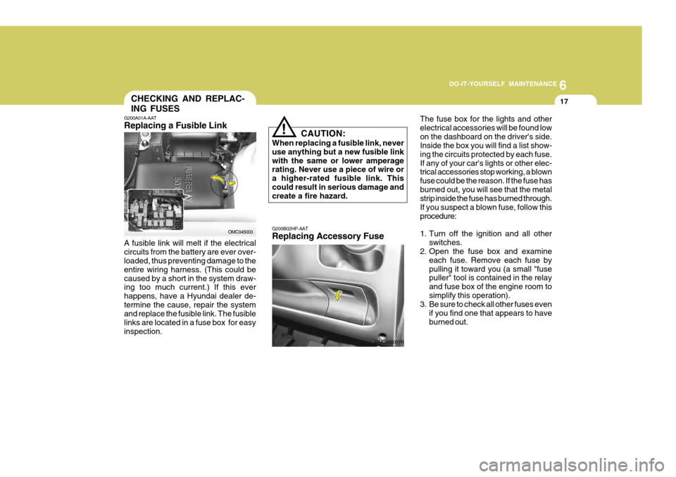
G200A01A-AAT Replacing a Fusible Link
OMC045003
A fusible link will melt if the electrical circuits from the battery are ever over- loaded, thus preventing damage to the entire wiring harness. (This could becaused by a short in the system draw- ing too much current.) If this ever happens, have a Hyundai dealer de-termine the cause, repair the system and replace the fusible link. The fusible links are located in a fuse box for easyinspection.
OMC045001R
Page 199 of 232
6 DO-IT-YOURSELF MAINTENANCE
18
G200B02L
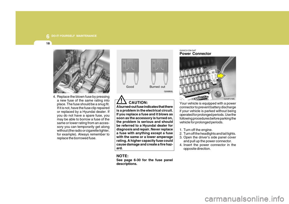
4. Replace the blown fuse by pressing a new fuse of the same rating into place. The fuse should be a snug fit. If it is not, have the fuse clip repaired or replaced by a Hyundai dealer. If you do not have a spare fuse, youmay be able to borrow a fuse of the same or lower rating from an acces- sory you can temporarily get alongwithout (the radio or cigarette lighter, for example). Always remember to replace the borrowed fuse. Good B
urned out
CAUTION:
A burned-out fuse indicates that there is a problem in the electrical circuit. If you replace a fuse and it blows assoon as the accessory is turned on, the problem is serious and should be referred to a Hyundai dealer fordiagnosis and repair. Never replace a fuse with anything except a fuse with the same or a lower amperagerating. A higher capacity fuse could cause damage and create a fire haz- ard. NOTE: See page 6-30 for the fuse panel descriptions.
!
G200B02MC G200C01CM-GAT Power Connector Your vehicle is equipped with a power connector to prevent battery dischargeif your vehicle is parked without being operated for prolonged periods. Use the following procedures before parking thevehicle for prolonged periods.
1. Turn off the engine.
2. Turn off the headlights and tail lights.
3. Open the driver’s side panel cover
and pull up the power connector.
4. Insert the power connector in the opposite direction.
G200F01MC
Page 200 of 232
6
DO-IT-YOURSELF MAINTENANCE
19
!
CHECKING THE BATTERY
o If battery fluid is on your skin, flushthe affected areas with water for at least 15 minutes and then seek medi- cal assistance.
o If battery fluid is in your eyes, rinse
out your eyes with water and getmedical assistance as soon as pos- sible. While you are being driven toget medical assistance, continue to rinse your eyes by using a sponge or soft cloth saturated with water.
o If you swallow battery fluid, drink a large quantity of water or milk fol-lowed by milk of magnesia, eat araw egg or drink vegetable oil. Get medical assistance as soon as pos- sible.
While batteries are being charged (ei- ther by a battery charger or by the vehicle's alternator), they produce ex-plosive gases. Always observe these warnings to reduce the risk of injury:
o Charge batteries only in a well ven- tilated area.
o Do not permit flames, sparks or smoking in the area.
o Keep children away from the area.
G210A01A-DAT
WARNING:
Batteries can be dangerous! When working with batteries, care- fully observe the following precau-tions to avoid serious injuries.
The fluid in the battery contains a strong solution of sulfuric acid, which is poi- sonous and highly corrosive. Be carefulnot to spill it on yourself or the car. If you do spill battery fluid on yourself, imme- diately do the following:
OMC055018
NOTE:
o If the power connector is pulled
up from the fuse panel, the warn- ing chime, audio, clock and inte-rior lamps, etc., will not operate. The following items must be reset after replacement.- Digital Clock - Trip computer
- Automatic heating and cooling control system
- Audio
o Even though the power connector is pulled up, the battery can stillbe discharged by operation of the headlights or other electrical de-vices.
Page 203 of 232
6 DO-IT-YOURSELF MAINTENANCE
22HEADLIGHT AIMING ADJUSTMENT
G290A03A-DAT Before performing aiming adjustment, make sure of the following.
1. Keep all tyres inflated to the correct
pressure.
2. Place the vehicle on level ground and press the front bumper & rear bumper down several times. Placethe vehicle at a distance of 3,000 mm (118 in.) from the test wall.
3. See that the vehicle is unloaded (except for full levels of coolant,engine oil and fuel, and spare tyre, jack, and tools).Have the driver or equivalent weight placed in driver's seat.
4. Clean the head light lenses and turn on the headlights (low beam).
NOTE:
o Grinding noise from the power
steering pump may be heard im- mediately after the engine is startedin extremely cold conditions (be- low - 20°C). If the noise stops during warm up, there is no ab-normal function in the system. It is due to a power steering fluid characteristic in extremely coldconditions.
o Do not start the engine when the
power steering oil reservoir isempty. G240A01A-DAT POWER STEERING HOSES It is suggested that you check the power steering hose connections forfluid leakage at those intervals speci- fied in the vehicle maintenance sched- ule in Section 5. The power steeringhoses should be replaced if there is severe surface cracking, pulling, scuff- ing or worn spots. Deterioration of thehoses could cause premature failure.
Page 204 of 232
6
DO-IT-YOURSELF MAINTENANCE
23
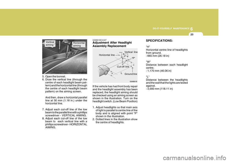
If the vehicle has had front body repair and the headlight assembly has been replaced, the headlight aiming shouldbe checked using an aiming screen as shown in the illustration. Turn on the headlight switch. (Low Beam Position)
1. Adjust headlights so that main axis
of light is parallel to centre line of the body and is aligned with point "P" shown in the illustration.
2. Dotted lines in the illustration show the centre of headlights.
G290B01MCA-DAT Adjustment After Headlight Assembly Replacement
SPECIFICATIONS: "H" Horizontal centre line of headlightsfrom ground. : 665 mm (26.18 in) "W" Distance between each headlight centre.: 1,170 mm (46.06 in) "L" Distance between the headlights and the wall that the lights are tested against.: 3,000 mm (118.11 in)
Horizontal aimingVertical aiming
5. Open the bonnet.
6. Draw the vertical line (through the centre of each headlight beam pat- tern) and the horizontal line (through the centre of each headlight beampattern) on the aiming screen. And then, draw a horizontal parallel line at 30 mm (1.18 in.) under the horizontal line.
7. Adjust each cut-off line of the low beam to the parallel line with a phillips screwdriver - VERTICAL AIMING.
8. Adjust each cut-off line of the low beam to each vertical line with aphillips screwdriver - HORIZONTALAIMING. G290A03MC
G290B01B
L
W
H
H Cut-off line
Ground line
"P"
Horizontal line
Vertical line30 mm
Page 230 of 232
10
INDEX
3
E Electronic Stability Program (ESP) ...........................2-12
Emission Contro l System ............................................ 7-2
Engine Before starting the engine ........................................ 2-3Compartment ............................................................ 6-2
Coolant ..................................................................... 6-7
If the engine overheats ............................................. 3-4
Number ..................................................................... 8-3
Oil ............................................................................. 6-4 Starting ..................................................................... 2-5
Engine Exhaust Can Be Dangerous ............................ 2-2
FFog Light Front ....................................................................... 1-67
Rear ........................................................................ 1-67
Front Seats Adjustable front seats ............................................. 1-14
Adjustable headrests .............................................. 1-15
Adjusting seat forward and rearward .......................1-14
Adjusting seatback angle ....................................... 1-14
Fuel
Capacity ................................................................... 9-2
Gauge ..................................................................... 1-55
Recommendations .................................................... 1-2
Fuel Filler Lid
Remote release ...................................................... 1-80
Fuses ........................................................................ 6-17
Fuse Panel description .............................................. 6-30G General Checks
........................................................... 6-3
Glove Box ................................................................. 1-75
H Hand Brake ................................................................ 1-78
Hazard Warning System ............................................ 1-66
Headlight Aiming Adjustment..................................... 6-22
Heating and Cooling Control ......................................1-89
Heating and Ventilation .............................................. 1-90
Air flow control ........................................................ 1-91
Air intake control .................................................... 1-90
Bi-level heati ng ....................................................... 1-94
Demisting/Defogging ............................................... 1-94
Fan speed control ................................................... 1-90
Temperature control ................................................ 1-93
High-Mounted Rear Stop Light................................... 1-79
Horn ........................................................................... 1-87
IImmobiliser System ..................................................... 1-3
Instrument Cluster and Indicator Lights ..................... 1-46
Instrument Panel Light Control (Rheostat) .................1-66
Interior Light
Interior light ............................................................. 1-73
Map light ................................................................. 1-73
JJump Starting .............................................................. 3-3
Page 232 of 232
10
INDEX
5
T Tachometer ................................................................ 1-56
Tail Gate .................................................................... 1-82
Theft-Alarm system ..................................................... 1-8
Towing
A trailer (or vehicle) ................................................ 2-21
Emergency ............................................................. 3-11
If your vehicle must be towed .................................. 3-9
Trailer or Vehicl e towing ............................................ 2-21
Transaxle Automatic ................................................................. 2-8
Automatic transaxle fluid checking ......................... 6-11
Manual ...................................................................... 2-6
Manual transaxle oil checking ................................ 6-11
Trip Computer ............................................................ 1-58
Trip Odometer ............................................................ 1-57
Tyre
Balancing .................................................................. 8-6
Chains ...................................................................... 8-5
Information ................................................................ 8-3
Pressure ................................................................... 8-3
Replacement ............................................................. 8-6
Rotation .................................................................... 8-5
Snow tyres ............................................................... 8-4
Spare tyre ................................................................. 3-5Traction ..................................................................... 8-6
Wheel and tyre changing .......................................... 3-6
VVehicle Identifi cation Number ...................................... 8-2 WWarning and Indicator
Lights ..................................... 1-50
Washer Reservoir ...................................................... 6-10
Window Glass ............................................................ 1-11
Power windows ....................................................... 1-12
Windshield Wiper and Washer ...................................1-63
Adjustable intermittent wiper operation ...................1-65
Rear window wiper and washer ...............................1-65
Windshield Wiper Blades ............................................. 6-9
Winter Driving ............................................................ 2-19