2009 GMC SAVANA PASSENGER brake
[x] Cancel search: brakePage 240 of 406
Turn Signals When Towing a Trailer
The arrows on the instrument panel flash whenever
signaling a turn or lane change. Properly hooked up, the
trailer lamps also flash, telling other drivers the vehicle
is turning, changing lanes or stopping.
When towing a trailer, the arrows on the instrument
panel flash for turns even if the bulbs on the trailer
are burned out. For this reason you may think other
drivers are seeing the signal when they are not.
It is important to check occasionally to be sure the
trailer bulbs are still working.
Driving On Grades
Reduce speed and shift to a lower gearbeforestarting
down a long or steep downgrade. If the transmission is
not shifted down, the brakes might have to be used so
much that they would get hot and no longer work well.The vehicle can tow in D (Drive). Shift the transmission
to a lower gear if the transmission shifts too often
under heavy loads and/or hilly conditions.
When towing at high altitude on steep uphill grades,
consider the following: Engine coolant will boil at a lower
temperature than at normal altitudes. If the engine is
turned off immediately after towing at high altitude on
steep uphill grades, the vehicle may show signs similar to
engine overheating. To avoid this, let the engine run while
parked, preferably on level ground, with the automatic
transmission in P (Park) for a few minutes before turning
the engine off. If the overheat warning comes on, see
Engine Overheating on page 5-31.
4-38
Page 241 of 406
Parking on Hills
{CAUTION:
Parking the vehicle on a hill with the trailer
attached can be dangerous. If something goes
wrong, the rig could start to move. People can be
injured, and both the vehicle and the trailer can be
damaged. When possible, always park the rig on a
flat surface.
If parking the rig on a hill:
1. Press the brake pedal, but do not shift the
transmission into P (Park) yet. Turn the wheels into
the curb if facing downhill or into traffic if facing
uphill.
2. Have someone place chocks under the trailer
wheels.
3. When the wheel chocks are in place, release the
brake pedal until the chocks absorb the load.
4. Reapply the brake pedal. Then apply the parking
brake and shift into P (Park).
5. Release the brake pedal.
Leaving After Parking on a Hill
1. Apply and hold the brake pedal while you:
•start the engine,
•shift into a gear, and
•release the parking brake.
2. Let up on the brake pedal.
3. Drive slowly until the trailer is clear of the chocks.
4. Stop and have someone pick up and store the
chocks.
Maintenance When Trailer Towing
The vehicle needs service more often when pulling a
trailer. See this manual’s Maintenance Schedule
or Index for more information. Things that are especially
important in trailer operation are automatic transmission
fluid, engine oil, axle lubricant, belts, cooling system
and brake system. It is a good idea to inspect
these before and during the trip.
Check periodically to see that all hitch nuts and bolts
are tight.
4-39
Page 242 of 406
Trailer Wiring Harness
The optional heavy-duty trailer wiring package includes
a wiring harness, with a seven-pin connector at the
rear of the vehicle and a four-wire harness assembly
under the driver side of the instrument panel. The
four-wire harness assembly comes without a connector.
If the vehicle does not have a trailer hitch, the
seven-wire harness assembly with connector is taped
together and located in a frame pocket at the driver side
rear left corner of the frame.
If the vehicle has a trailer hitch, the seven-wire harness
assembly with connector is attached to a bracket on
the hitch platform. In both cases, the seven-wire harness
has a connector and includes a 30-amp feed wire.
The seven-wire harness connector contains the following
trailer circuits:
•Light Green: Back-up Lamps (10A fuse)**
•White: Ground
•Dark Blue: Trailer Brake Signal
•Dark Green: Right Rear Stop and Turn Signal*
•Red/Black Stripe: Battery Feed (30A Fuse)
•Brown: Trailer Park Lamp Supply Voltage
(15A fuse)**
•Yellow: Left Rear Stop and Turn Signal *The four-wire harness (without connector) contains the
following circuits:
•Black: Ground
•Red/White: Battery Feed
•Dark Blue: Trailer Brake Signal
•Light Blue: CHMSL/Stoplamp Supply Voltage
* If the vehicle is a cutaway with trailer provisions, a
15 amp fuse will be shared for both left/stop trailer turn
and right/stop trailer turn signals. However, the
cutaway lighting connector will have a 10 amp fuse for
each signal.
** If the vehicle is a cutaway with trailer provisions, a
15 amp fuse will be shared for trailer park lamps
and cutaway rear lighting connector park lamps. Also, a
10 amp fuse will be shared for trailer back-up lamps
and cutaway rear lighting connector back-up lamps.
4-40
Page 243 of 406
Service............................................................5-3
Accessories and Modifications..........................5-3
California Proposition 65 Warning.....................5-4
California Perchlorate Materials Requirements.....5-4
Doing Your Own Service Work.........................5-4
Adding Equipment to the Outside of the
Vehicle......................................................5-5
Fuel................................................................5-5
Gasoline Octane............................................5-6
Gasoline Specifications....................................5-6
California Fuel...............................................5-6
Additives.......................................................5-7
Fuel E85 (85% Ethanol)..................................5-8
Fuels in Foreign Countries...............................5-9
Filling the Tank............................................5-10
Filling a Portable Fuel Container.....................5-12
Checking Things Under the Hood....................5-12
Hood Release..............................................5-13
Engine Compartment Overview.......................5-14
Engine Oil...................................................5-15
Engine Oil Life System..................................5-18
Engine Air Cleaner/Filter................................5-20
Automatic Transmission Fluid.........................5-21
Cooling System............................................5-24
Engine Coolant.............................................5-25Radiator Pressure Cap..................................5-31
Engine Overheating.......................................5-31
Engine Fan Noise.........................................5-33
Power Steering Fluid.....................................5-34
Windshield Washer Fluid................................5-35
Brakes........................................................5-36
Battery........................................................5-39
Jump Starting...............................................5-40
All-Wheel Drive..............................................5-45
Rear Axle
.......................................................5-46
Front Axle......................................................5-46
Noise Control System.....................................5-47
Tampering with Noise Control System
Prohibited.................................................5-47
Bulb Replacement..........................................5-49
Halogen Bulbs..............................................5-49
Headlamps..................................................5-49
Front Turn Signal, Sidemarker and
Parking Lamps..........................................5-51
Center High-Mounted Stoplamp (CHMSL).........5-52
Taillamps.....................................................5-52
Replacement Bulbs.......................................5-53
Windshield Wiper Blade Replacement..............5-54
Section 5 Service and Appearance Care
5-1
Page 245 of 406
Service
For service and parts needs, visit your dealer/retailer.
You will receive genuine GM parts and GM-trained and
supported service people.
Genuine GM parts have one of these marks:
Accessories and Modi�cations
When non-dealer/non-retailer accessories are added
to the vehicle, they can affect vehicle performance and
safety, including such things as airbags, braking, stability,
ride and handling, emissions systems, aerodynamics,
durability, and electronic systems like antilock brakes,
traction control, and stability control. Some of these
accessories could even cause malfunction or damage
not covered by the vehicle warranty.
Damage to vehicle components resulting from the
installation or use of non-GM certified parts, including
control module modifications, are not covered under the
terms of the vehicle warranty and may affect remaining
warranty coverage for affected parts.
GM Accessories are designed to complement and
function with other systems on the vehicle. Your GM
dealer/retailer can accessorize the vehicle using genuine
GM Accessories. When you go to your GM dealer/retailer
and ask for GM Accessories, you will know that
GM-trained and supported service technicians will
perform the work using genuine GM Accessories.
Also, seeAdding Equipment to Your Airbag-Equipped
Vehicle on page 1-78.
5-3
Page 254 of 406
Filling a Portable Fuel Container
{CAUTION:
Never fill a portable fuel container while it is in
the vehicle. Static electricity discharge from the
container can ignite the fuel vapor. You can be
badly burned and the vehicle damaged if this
occurs. To help avoid injury to you and others:
•Dispense fuel only into approved containers.
•Do not fill a container while it is inside a
vehicle, in a vehicle’s trunk, pickup bed,
or on any surface other than the ground.
•Bring the fill nozzle in contact with the inside
of the fill opening before operating the nozzle.
Contact should be maintained until the filling
is complete.
•Do not smoke while pumping fuel.
•Do not use a cellular phone while
pumping fuel.
Checking Things Under
the Hood
{CAUTION:
Things that burn can get on hot engine or fuel
operated heater (FOH) parts and start a fire.
These include liquids like fuel, oil, coolant, brake
fluid, windshield washer and other fluids, and
plastic or rubber. You or others could be burned.
Be careful not to drop or spill things that will burn
onto a hot engine or fuel operated heater (FOH).
5-12
Page 257 of 406
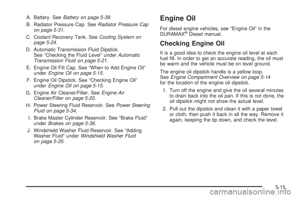
A. Battery. SeeBattery on page 5-39.
B. Radiator Pressure Cap. SeeRadiator Pressure Cap
on page 5-31.
C. Coolant Recovery Tank. SeeCooling System on
page 5-24.
D. Automatic Transmission Fluid Dipstick.
See “Checking the Fluid Level” underAutomatic
Transmission Fluid on page 5-21.
E. Engine Oil Fill Cap. See “When to Add Engine Oil”
underEngine Oil on page 5-15.
F. Engine Oil Dipstick. See “Checking Engine Oil”
underEngine Oil on page 5-15.
G. Engine Air Cleaner/Filter. SeeEngine Air
Cleaner/Filter on page 5-20.
H. Power Steering Fluid Reservoir. SeePower Steering
Fluid on page 5-34.
I. Brake Master Cylinder Reservoir. See “Brake Fluid”
underBrakes on page 5-36.
J. Windshield Washer Fluid Reservoir. See “Adding
Washer Fluid” underWindshield Washer Fluid
on page 5-35.Engine Oil
For diesel engine vehicles, see “Engine Oil” in the
DURAMAX®Diesel manual.
Checking Engine Oil
It is a good idea to check the engine oil level at each
fuel fill. In order to get an accurate reading, the oil must
be warm and the vehicle must be on level ground.
The engine oil dipstick handle is a yellow loop.
SeeEngine Compartment Overview on page 5-14
for the location of the engine oil dipstick.
1. Turn off the engine and give the oil several minutes
to drain back into the oil pan. If this is not done, the
oil dipstick might not show the actual level.
2. Pull out the dipstick and clean it with a paper towel
or cloth, then push it back in all the way. Remove it
again, keeping the tip down, and check the level.
5-15
Page 265 of 406
Checking the Fluid Level
Prepare your vehicle as follows:
1. Park your vehicle on a level place. Keep the engine
running.
2. With the parking brake applied, place the shift lever
in P (PARK).
3. With your foot on the brake pedal, move the shift
lever through each gear range, pausing for about
three seconds in each range. Then, position
the shift lever in P (PARK).
4. Let the engine run at idle for three minutes or more.
Then, without shutting off the engine, follow these steps:
The transmission dipstick
is located near the center
of the engine compartment
and will be labeled with
the graphic shown.SeeEngine Compartment Overview on page 5-14for
more information on location.
1. Flip the handle up and then pull out the dipstick
and wipe it with a clean rag or paper towel.
2. Push it back in all the way, wait three seconds
and then pull it back out again.
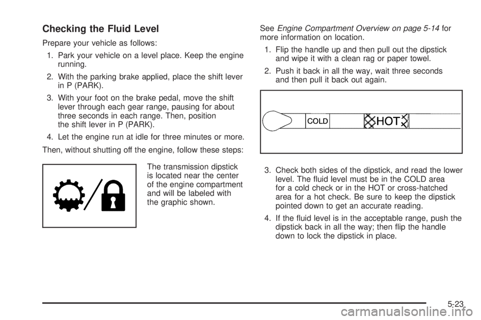
3. Check both sides of the dipstick, and read the lower
level. The fluid level must be in the COLD area
for a cold check or in the HOT or cross-hatched
area for a hot check. Be sure to keep the dipstick
pointed down to get an accurate reading.
4. If the fluid level is in the acceptable range, push the
dipstick back in all the way; then flip the handle
down to lock the dipstick in place.
5-23