Page 311 of 418
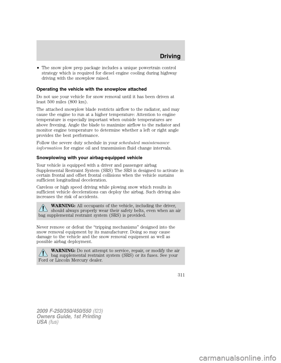
•The snow plow prep package includes a unique powertrain control
strategy which is required for diesel engine cooling during highway
driving with the snowplow raised.
Operating the vehicle with the snowplow attached
Do not use your vehicle for snow removal until it has been driven at
least 500 miles (800 km).
The attached snowplow blade restricts airflow to the radiator, and may
cause the engine to run at a higher temperature: Attention to engine
temperature is especially important when outside temperatures are
above freezing. Angle the blade to maximize airflow to the radiator and
monitor engine temperature to determine whether a left or right angle
provides the best performance.
Follow the severe duty schedule in yourscheduled maintenance
informationfor engine oil and transmission fluid change intervals.
Snowplowing with your airbag-equipped vehicle
Your vehicle is equipped with a driver and passenger airbag
Supplemental Restraint System (SRS) The SRS is designed to activate in
certain frontal and offset frontal collisions when the vehicle sustains
sufficient longitudinal deceleration.
Careless or high speed driving while plowing snow which results in
sufficient vehicle decelerations can deploy the airbag. Such driving also
increases the risk of accidents.
WARNING:All occupants of the vehicle, including the driver,
should always properly wear their safety belts, even when an air
bag supplemental restraint system (SRS) is provided.
Never remove or defeat the “tripping mechanisms” designed into the
snow removal equipment by its manufacturer. Doing so may cause
damage to the vehicle and the snow removal equipment as well as
possible airbag deployment.
WARNING:Do not attempt to service, repair, or modify the air
bag supplemental restraint system (SRS) or its fuses. See your
Ford or Lincoln Mercury dealer.
2009 F-250/350/450/550(f23)
Owners Guide, 1st Printing
USA(fus)
Driving
311
Page 319 of 418

Fuse/Relay
LocationFuse Amp
RatingProtected Circuits
10 15A Cargo lamp, Puddle lamp, Switch
backlight
11 10A Not used (spare)
12 7.5A Power mirror switch, Driver
power seat (Memory)
13 5A Not used (spare)
14 10A Upfitter relay #3 feed
15 10A Climate control head
16 15A Upfitter Relay #4 Feed
17 20A All lock motor feeds
18 20A Heated seat relay feed
19 25A Not used (spare)
20 15A Adjustable pedals, Datalink
21 15A Fog lamp relay feed, Cornering
lamps
22 15A Park lamp relay feed
23 15A High beam headlight relay feed
24 20A Horn relay feed
25 10A Power telescoping mirror switch
Demand lamps - underhood and
illuminated visor (battery saver)
26 10A Cluster
27 20A Ignition switch feed, Passenger
compartment fuses 28, 42, 43, 44,
and 45, Engine compartment
starter relay coil #57 (Diesel
engine), Accessory shutoff control
module (if equipped) (Diesel
engine), Engine compartment
starter relay diode (gasoline
engines)
28 5A Radio
29 5A Not used (spare)
30 5A Not used (spare)
2009 F-250/350/450/550(f23)
Owners Guide, 1st Printing
USA(fus)
Roadside Emergencies
319
Page 320 of 418

Fuse/Relay
LocationFuse Amp
RatingProtected Circuits
31 10A Not used (spare)
32 10A Restraints Control Module (RCM),
Passenger Airbag Deactivation
Indicator
33 10A Trailer tow brake controller,
Trailer tow battery charge relay
coil
34 5A Not used (spare)
35 10A Reverse Sensing System (RSS),
4x4 module, 4x4 solenoid,
Traction control switch, Tow/Haul
switch (Diesel engine)
36 5A Passive Anti-Theft System (PATS)
transceiver, Cluster control
37 10A Dual automatic or Manual climate
control, PTC control
38 20A Subwoofer
39 20A Radio, Navigation radio and
amplifier
40 20A 4x4 module, Satellite radio
module, SYNC
41 15A Radio, Electrochromatic rear view
mirror, Lock switch illumination
42 10A Heated seat relay coil, Upfitter
switch relay coils, Heated mirror
relay coil
43 10A Fuel tank selector switch, 4x4
module
44 10A Run customer access feed (PTO)
45 5A Front wiper logic, Blower motor
relay coil
46 7.5A Not used (spare)
47 30A Circuit
BreakerPower windows, Moon roof,
Power Sliding Backlite
48 Relay Delayed accessory
2009 F-250/350/450/550(f23)
Owners Guide, 1st Printing
USA(fus)
Roadside Emergencies
320
Page 322 of 418
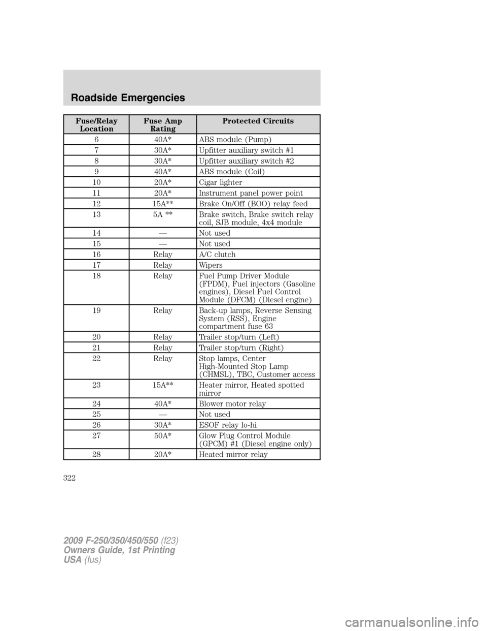
Fuse/Relay
LocationFuse Amp
RatingProtected Circuits
6 40A* ABS module (Pump)
7 30A* Upfitter auxiliary switch #1
8 30A* Upfitter auxiliary switch #2
9 40A* ABS module (Coil)
10 20A* Cigar lighter
11 20A* Instrument panel power point
12 15A** Brake On/Off (BOO) relay feed
13 5A ** Brake switch, Brake switch relay
coil, SJB module, 4x4 module
14 — Not used
15 — Not used
16 Relay A/C clutch
17 Relay Wipers
18 Relay Fuel Pump Driver Module
(FPDM), Fuel injectors (Gasoline
engines), Diesel Fuel Control
Module (DFCM) (Diesel engine)
19 Relay Back-up lamps, Reverse Sensing
System (RSS), Engine
compartment fuse 63
20 Relay Trailer stop/turn (Left)
21 Relay Trailer stop/turn (Right)
22 Relay Stop lamps, Center
High-Mounted Stop Lamp
(CHMSL), TBC, Customer access
23 15A** Heater mirror, Heated spotted
mirror
24 40A* Blower motor relay
25 — Not used
26 30A* ESOF relay lo-hi
27 50A* Glow Plug Control Module
(GPCM) #1 (Diesel engine only)
28 20A* Heated mirror relay
2009 F-250/350/450/550(f23)
Owners Guide, 1st Printing
USA(fus)
Roadside Emergencies
322
Page 323 of 418
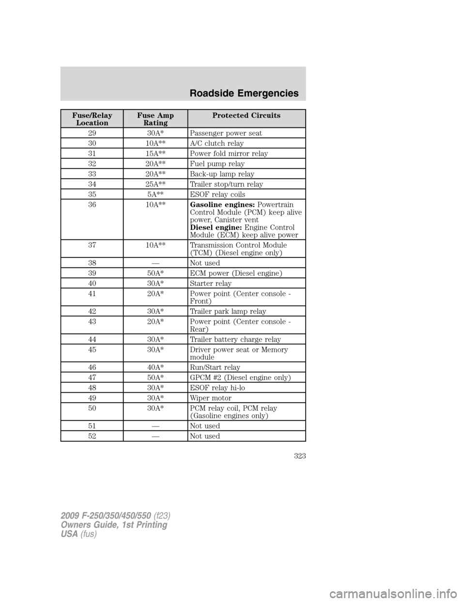
Fuse/Relay
LocationFuse Amp
RatingProtected Circuits
29 30A* Passenger power seat
30 10A** A/C clutch relay
31 15A** Power fold mirror relay
32 20A** Fuel pump relay
33 20A** Back-up lamp relay
34 25A** Trailer stop/turn relay
35 5A** ESOF relay coils
36 10A**Gasoline engines:Powertrain
Control Module (PCM) keep alive
power, Canister vent
Diesel engine:Engine Control
Module (ECM) keep alive power
37 10A** Transmission Control Module
(TCM) (Diesel engine only)
38 — Not used
39 50A* ECM power (Diesel engine)
40 30A* Starter relay
41 20A* Power point (Center console -
Front)
42 30A* Trailer park lamp relay
43 20A* Power point (Center console -
Rear)
44 30A* Trailer battery charge relay
45 30A* Driver power seat or Memory
module
46 40A* Run/Start relay
47 50A* GPCM #2 (Diesel engine only)
48 30A* ESOF relay hi-lo
49 30A* Wiper motor
50 30A* PCM relay coil, PCM relay
(Gasoline engines only)
51 — Not used
52 — Not used
2009 F-250/350/450/550(f23)
Owners Guide, 1st Printing
USA(fus)
Roadside Emergencies
323
Page 324 of 418
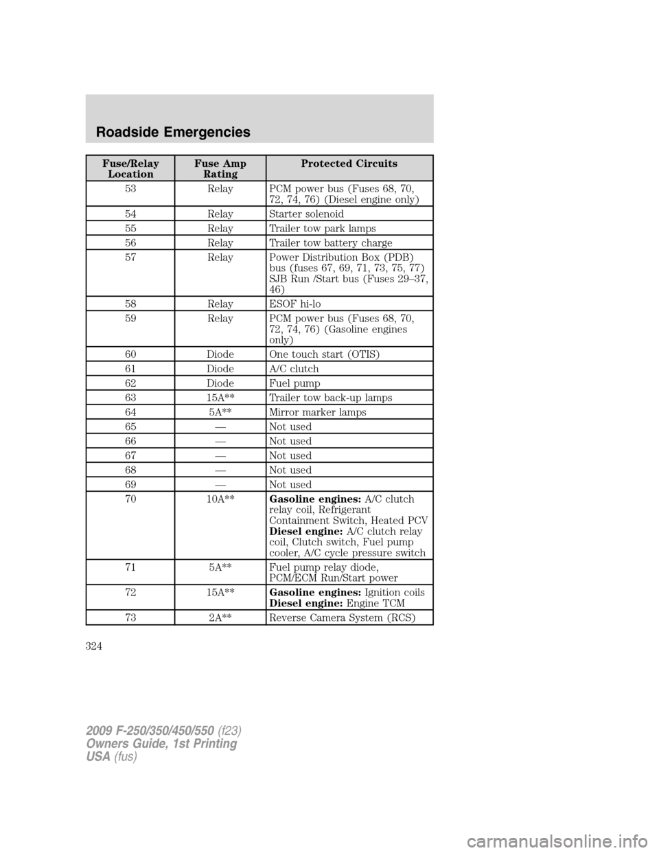
Fuse/Relay
LocationFuse Amp
RatingProtected Circuits
53 Relay PCM power bus (Fuses 68, 70,
72, 74, 76) (Diesel engine only)
54 Relay Starter solenoid
55 Relay Trailer tow park lamps
56 Relay Trailer tow battery charge
57 Relay Power Distribution Box (PDB)
bus (fuses 67, 69, 71, 73, 75, 77)
SJB Run /Start bus (Fuses 29–37,
46)
58 Relay ESOF hi-lo
59 Relay PCM power bus (Fuses 68, 70,
72, 74, 76) (Gasoline engines
only)
60 Diode One touch start (OTIS)
61 Diode A/C clutch
62 Diode Fuel pump
63 15A** Trailer tow back-up lamps
64 5A** Mirror marker lamps
65 — Not used
66 — Not used
67 — Not used
68 — Not used
69 — Not used
70 10A**Gasoline engines:A/C clutch
relay coil, Refrigerant
Containment Switch, Heated PCV
Diesel engine:A/C clutch relay
coil, Clutch switch, Fuel pump
cooler, A/C cycle pressure switch
71 5A** Fuel pump relay diode,
PCM/ECM Run/Start power
72 15A**Gasoline engines:Ignition coils
Diesel engine:Engine TCM
73 2A** Reverse Camera System (RCS)
2009 F-250/350/450/550(f23)
Owners Guide, 1st Printing
USA(fus)
Roadside Emergencies
324
Page 325 of 418

Fuse/Relay
LocationFuse Amp
RatingProtected Circuits
74 20A**Gasoline engines:VPWR:
HEGO, CMS, MAFS, EVMV,
CMCV, VCT, IMTV
Diesel engine:VPWR: Engine
loads
75 5A** Back-up relay coil power
76 20A**Gasoline engines:VPWR: PCM
Diesel engine:VPWR: ECM
77 10A** ABS module logic
* Cartridge fuses ** Mini fuses
CHANGING A FLAT TIRE
If you get a flat tire while driving:
•do not brake heavily.
•gradually decrease the vehicle’s speed.
•hold the steering wheel firmly.
•slowly move to a safe place on the side of the road.
Your vehicle may be equipped with a conventional spare tire that is
different in one or more of the following: type, brand, size, speed rating
and tread design. If this is the case, this dissimilar spare tire is still rated
for your vehicle loads (GAWR and GVWR).Temporary spare tires are not
equipped with Tire Pressure Monitor System (TPMS) sensors if the
system is present.
WARNING:The use of tire sealant may damage your Tire
Pressure Monitoring System (if equipped) and should not be
used.
WARNING:If your vehicle is equipped with a Tire Pressure
Monitoring System, refer toTire Pressure Monitoring System
in theTires, Wheels and Loadingchapter for more information. If the
tire pressure monitor sensor becomes damaged, it will no longer
function.
2009 F-250/350/450/550(f23)
Owners Guide, 1st Printing
USA(fus)
Roadside Emergencies
325
Page 341 of 418
5. Repeat this tightness check procedure when servicing the spare tire
pressure (every six months, perscheduled maintenance information),
or at any time that the spare tire is disturbed through service of other
components.
6. If removed, install the spare tire lock (if equipped) into the bumper
drive tube with the spare tire lock key (if equipped) and jack handle.
WHEEL LUG NUT TORQUE SPECIFICATIONS
On vehicles equipped with single rear wheels, retighten the lug nuts to
the specified torque at 500 miles (800 km) after any wheel disturbance
(tire rotation, changing a flat tire, wheel removal, etc.).
On vehicles equipped with dual rear wheels, retighten the wheel lug nuts
to the specified torque at 100 miles (160 km), and again at 500 miles
(800 km) of new vehicle operation and after any wheel disturbance (tire
rotation, changing a flat tire, wheel removal, etc.).
Bolt size Wheel lug nut torque*
lb.ft. N•m
M14 x 1.5 165 224
* Torque specifications are for nut and bolt threads free of dirt and
rust. Use only Ford recommended replacement fasteners.
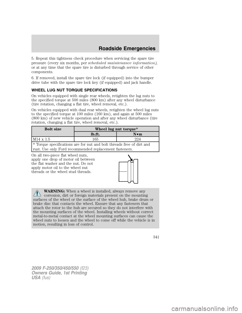
On all two-piece flat wheel nuts,
apply one drop of motor oil between
the flat washer and the nut. Do not
apply motor oil to the wheel nut
threads or the wheel stud threads.
WARNING:When a wheel is installed, always remove any
corrosion, dirt or foreign materials present on the mounting
surfaces of the wheel or the surface of the wheel hub, brake drum or
brake disc that contacts the wheel. Ensure that any fasteners that
attach the rotor to the hub are secured so they do not interfere with
the mounting surfaces of the wheel. Installing wheels without correct
metal-to-metal contact at the wheel mounting surfaces can cause the
wheel nuts to loosen and the wheel to come off while the vehicle is in
motion, resulting in loss of control.
2009 F-250/350/450/550(f23)
Owners Guide, 1st Printing
USA(fus)
Roadside Emergencies
341