2009 FORD SUPER DUTY warning
[x] Cancel search: warningPage 22 of 103
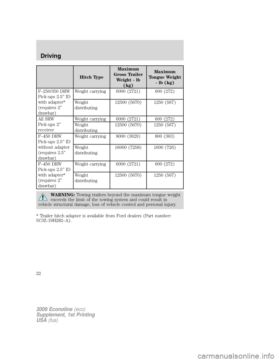
Hitch TypeMaximum
Gross Trailer
Weight-lb
(kg)Maximum
Tongue Weight
- lb (kg)
F–250/350 DRW
Pick-ups 2.5” ID
with adapter*
(requires 2”
drawbar)Weight carrying 6000 (2721) 600 (272)
Weight
distributing12500 (5670) 1250 (567)
All SRW
Pick-ups 2”
receiverWeight carrying 6000 (2721) 600 (272)
Weight
distributing12500 (5670) 1250 (567)
F–450 DRW
Pick-ups 2.5” ID
without adapter
(requires 2.5”
drawbar)Weight carrying 8000 (3629) 800 (363)
Weight
distributing16000 (7258) 1600 (726)
F–450 DRW
Pick-ups 2.5” ID
with adapter*
(requires 2”
drawbar)Weight carrying 6000 (2721) 600 (272)
Weight
distributing12500 (5670) 1250 (567)
WARNING:Towing trailers beyond the maximum tongue weight
exceeds the limit of the towing system and could result in
vehicle structural damage, loss of vehicle control and personal injury.
* Trailer hitch adapter is available from Ford dealers (Part number:
5C3Z-19H282–A).
2009 Econoline(eco)
Supplement, 1st Printing
USA(fus)
Driving
22
Page 23 of 103
JUMP STARTING YOUR VEHICLE (E-SERIES ONLY)
The following procedure is for E-Series vehicles only. F-Super
Duty vehicles equipped with the 6.4L diesel engine can be jump
started using the same procedure as a gasoline engine; refer to
yourOwner’s Guidefor the jump starting procedure.
WARNING:The gases around the battery can explode if
exposed to flames, sparks, or lit cigarettes. An explosion could
result in injury or vehicle damage.
WARNING:Batteries contain sulfuric acid which can burn skin,
eyes and clothing, if contacted.
Do not attempt to push-start your vehicle. Automatic
transmissions do not have push-start capability; damage to the
automatic transmission may result.
Preparing your vehicle
When the batteries are disconnected or new batteries are installed, the
transmission must relearn its shift strategy. As a result, the transmission
may have firm and/or soft shifts. This operation is considered normal and
will not affect function or durability of the transmission. Over time, the
adaptive learning process will fully update transmission operation.
1.Use only a 12–volt supply to start your vehicle.
2. Do not disconnect the batteries of the disabled vehicle as this could
damage the vehicle’s electrical system.
3. Park the booster vehicle close to the passenger side of the disabled
vehicle making sure the two vehiclesdo nottouch. Set the parking
brake on both vehicles.
Note:This vehicle has two frame-mounted batteries located on the
passenger side frame rail, behind the front passenger door. A battery
positive (+) jumper stud is located on the frame rail behind the rear
most battery box.
2009 Econoline(eco)
Supplement, 1st Printing
USA(fus)
Roadside Emergencies
23
Page 26 of 103
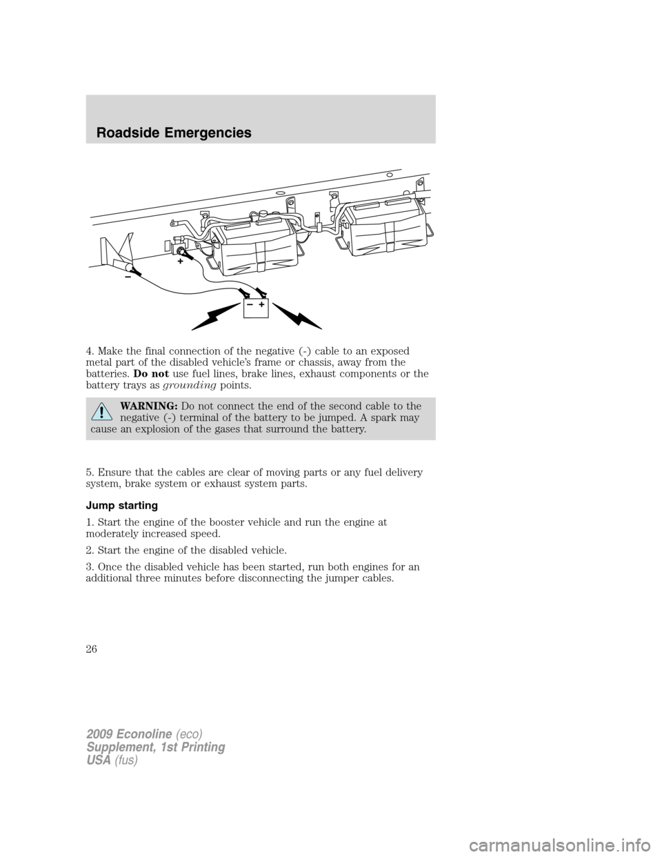
4. Make the final connection of the negative (-) cable to an exposed
metal part of the disabled vehicle’s frame or chassis, away from the
batteries.Do notuse fuel lines, brake lines, exhaust components or the
battery trays asgroundingpoints.
WARNING:Do not connect the end of the second cable to the
negative (-) terminal of the battery to be jumped. A spark may
cause an explosion of the gases that surround the battery.
5. Ensure that the cables are clear of moving parts or any fuel delivery
system, brake system or exhaust system parts.
Jump starting
1. Start the engine of the booster vehicle and run the engine at
moderately increased speed.
2. Start the engine of the disabled vehicle.
3. Once the disabled vehicle has been started, run both engines for an
additional three minutes before disconnecting the jumper cables.
2009 Econoline(eco)
Supplement, 1st Printing
USA(fus)
Roadside Emergencies
26
Page 31 of 103
WARNING:Failure to maintain the functional holes, in the
tailpipe section of the exhaust, clean and free of debris or
foreign material may result in the holes becoming blocked or plugged.
Do not modify or remove the tail-pipe section. Blocked or plugged
holes or removal/modification of the system could result in elevated
exhaust gas temperatures which may result in vehicle/property damage
or personal injury
WARNING:The normal operating temperature of the exhaust
system is very high. Never work around or attempt to repair any
part of the exhaust system until it has cooled. Use special care when
working around the diesel oxidation catalytic converter and/or the
diesel particulate filter (DPF). The diesel oxidation catalytic converter
and/or the DPF heats up to a high temperature after only a short
period of engine operation and can stay hot even after the engine is
turned off. Failure to follow these instructions may result in personal
injury.
2009 Econoline(eco)
Supplement, 1st Printing
USA(fus)
Cleaning
31
Page 39 of 103
Fuel filler cap
Your fuel tank filler cap has an indexed design with a 1/4 turn on/off
feature.
When fueling your vehicle:
1. Turn the engine off.
2. Carefully turn the filler cap counterclockwise until it spins off.
3. Pull to remove the cap from the fuel filler pipe.
4. To install the cap, align the tabs on the cap with the notches on the
filler pipe.
5. Turn the filler cap clockwise 1/4 of a turn until it clicks at least once.
If you must replace the fuel filler cap, replace it with a fuel filler
cap that is designed for your vehicle. The vehicle warranty may
be void for any damage to the fuel tank or fuel system if the
correct genuine Ford or Motorcraft fuel filler cap is not used.
WARNING:The fuel system may be under pressure. If the fuel
filler cap is venting vapor or if you hear a hissing sound, wait
until it stops before completely removing the fuel filler cap. Otherwise,
fuel may spray out and injure you or others.
WARNING:If you do not use the proper fuel filler cap,
excessive pressure or vacuum in the fuel tank may damage the
fuel system or cause the fuel cap to disengage in a collision, which may
result in possible personal injury.
FUEL FILTER/WATER SEPARATOR
Fuel Conditioner Module (FCM - E-Series)
The vehicle is equipped with a Fuel Conditioning Module (FCM) located
on the driver-side of the vehicle next to the transmission case.
Water should be drained from the
module assembly whenever the
warning light comes on. The WATER
IN FUEL light will come on when
approximately 0.2 pints (100 cc) of water accumulates in the module.
2009 Econoline(eco)
Supplement, 1st Printing
USA(fus)
Maintenance and Specifications
39
Page 40 of 103
Horizontal Fuel Conditioner Module (HFCM - F-Super Duty)
The vehicle is equipped with a Horizontal Fuel Conditioning Module
(HFCM) located on the frame-rail under the driver-side floorboard near
the transmission
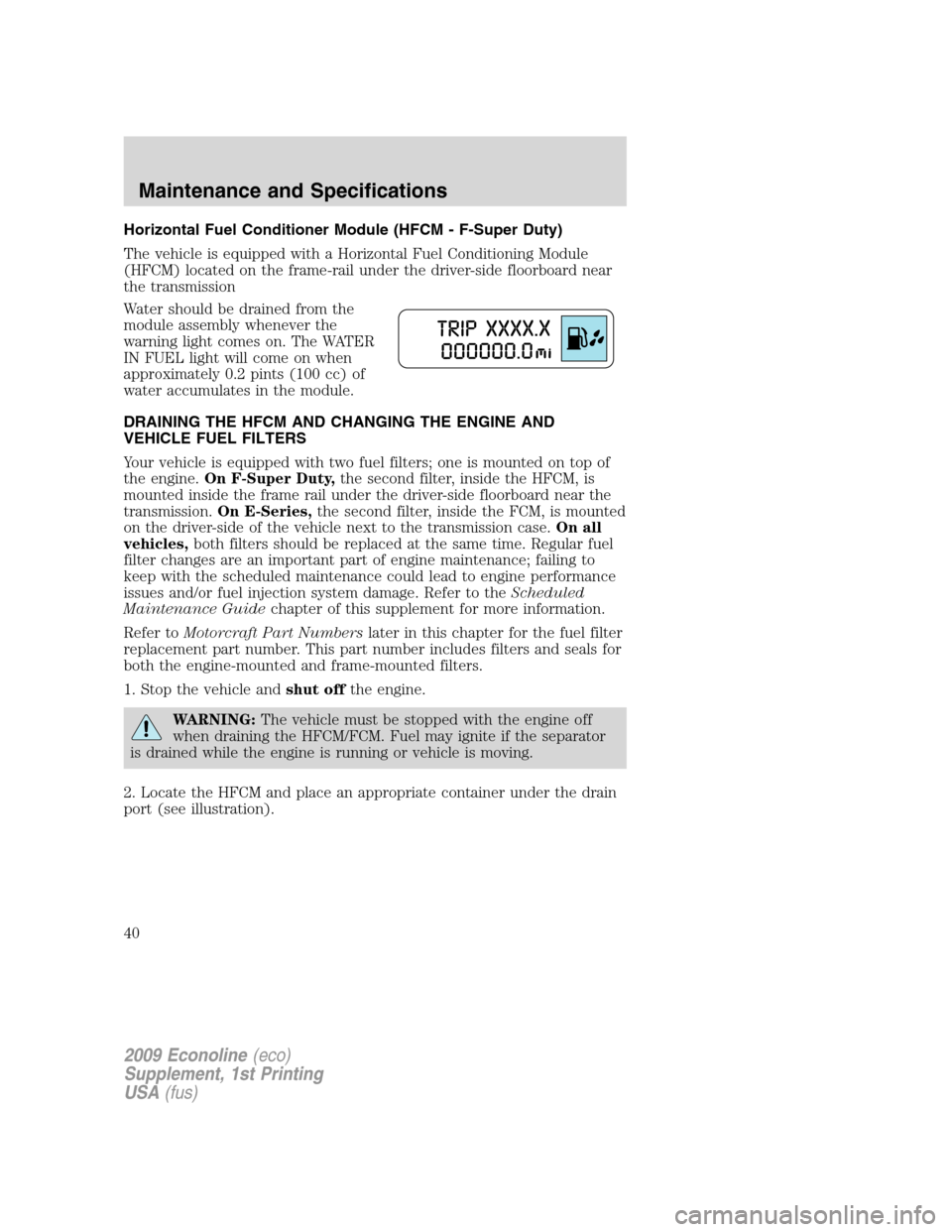
Water should be drained from the
module assembly whenever the
warning light comes on. The WATER
IN FUEL light will come on when
approximately 0.2 pints (100 cc) of
water accumulates in the module.
DRAINING THE HFCM AND CHANGING THE ENGINE AND
VEHICLE FUEL FILTERS
Your vehicle is equipped with two fuel filters; one is mounted on top of
the engine.On F-Super Duty,the second filter, inside the HFCM, is
mounted inside the frame rail under the driver-side floorboard near the
transmission.On E-Series,the second filter, inside the FCM, is mounted
on the driver-side of the vehicle next to the transmission case.On all
vehicles,both filters should be replaced at the same time. Regular fuel
filter changes are an important part of engine maintenance; failing to
keep with the scheduled maintenance could lead to engine performance
issues and/or fuel injection system damage. Refer to theScheduled
Maintenance Guidechapter of this supplement for more information.
Refer toMotorcraft Part Numberslater in this chapter for the fuel filter
replacement part number. This part number includes filters and seals for
both the engine-mounted and frame-mounted filters.
1. Stop the vehicle andshut offthe engine.
WARNING:The vehicle must be stopped with the engine off
when draining the HFCM/FCM. Fuel may ignite if the separator
is drained while the engine is running or vehicle is moving.
2. Locate the HFCM and place an appropriate container under the drain
port (see illustration).
2009 Econoline(eco)
Supplement, 1st Printing
USA(fus)
Maintenance and Specifications
40
Page 47 of 103
Changing engine oil and filter
Change your oil and filter according to thescheduled maintenance
informationin this supplement. Change more frequently if your vehicle
operation includes extended periods of idling or low-speed operation,
driving for a long time in cold temperatures or driving short distances.
See the following sectionEngine lubrication for severe service
operationfor all severe duty restrictions.
Refer toMotorcraft Part Numberslater in this chapter for the engine oil
filter part number. This filter protects your engine by filtering harmful,
abrasive or sludge particles and particles significantly smaller than most
available “will-fit” filters.
To replace the filter,
1. Unscrew the oil filter cap and wait a few seconds for the oil to drain
through the built-in drain valve.Note:The filter should be changed
before reinstalling the oil pan drain plug.
2. Reinstall and tighten the oil filter cap.
WARNING:Do not handle a hot oil filter with bare hands.
WARNING:Continuous contact with USED motor oil has caused
cancer in laboratory mice. Protect your skin by washing with
soap and water.
Engine lubrication for severe service operation
The following severe service operating conditions require unique engine
maintenance procedures:
•frequent or extended idling (over 10 minutes per hour of normal
driving).
•if vehicle is operated in sustained ambient temperatures below -10°F
(-23°C) or above 100°F (38°C)
•frequent low speed operation, consistent heavy traffic less than
25 mph (40 km/h)
•operating in severe dust conditions.
•towing a trailer over 1,000 miles (1,600 km)
•sustained, high speed driving at Gross Vehicle Weight Rating
(maximum loaded weight for vehicle operation)
2009 Econoline(eco)
Supplement, 1st Printing
USA(fus)
Maintenance and Specifications
47
Page 48 of 103
•use of biodiesel, up to and including 5% Biodiesel (B5)
•use of high sulfur diesel fuel
If you are operating your vehicle under any of these conditions, change
engine oil and filter every 5,000 miles (8,000 km).
AIR FILTER RESTRICTION GAUGE AND AIR FILTER
REPLACEMENT
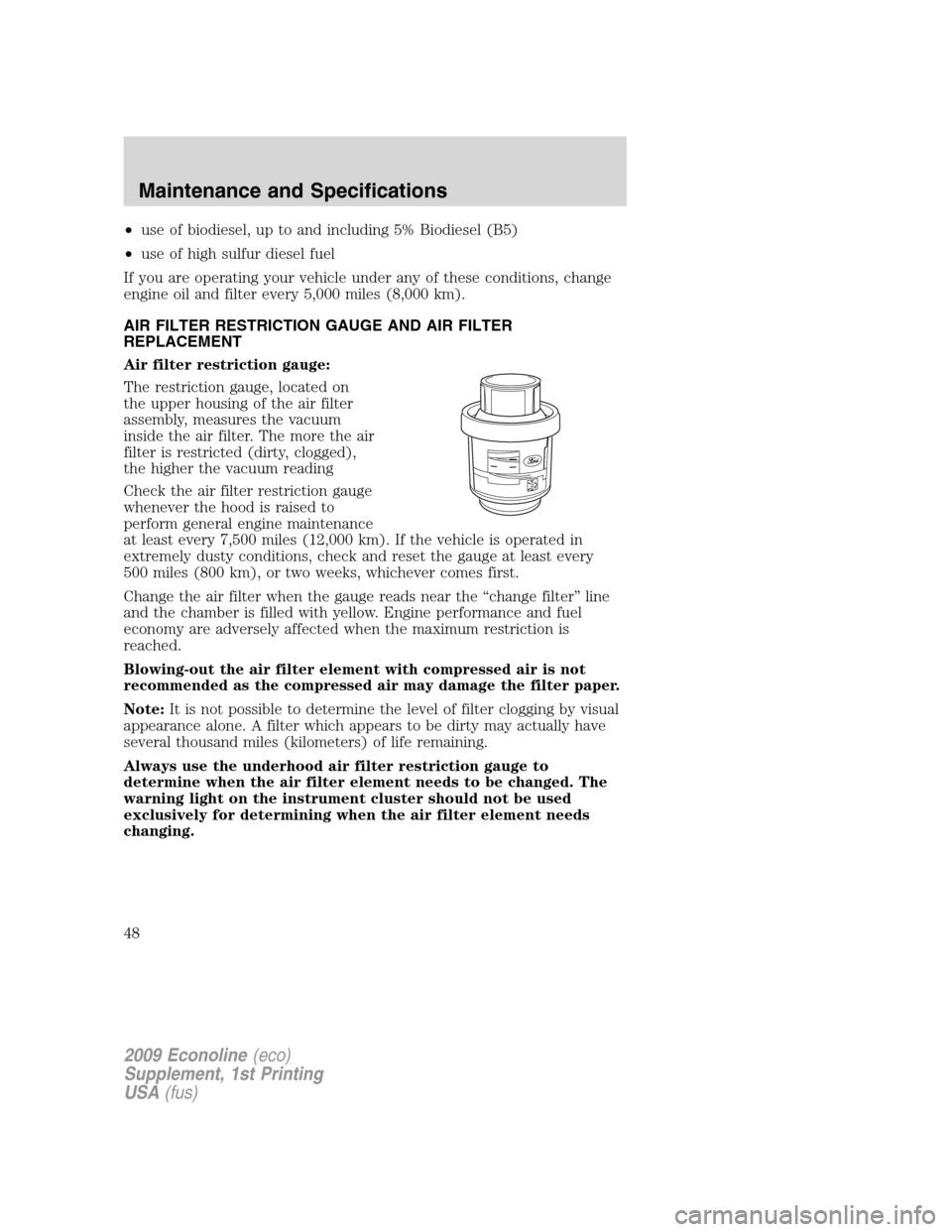
Air filter restriction gauge:
The restriction gauge, located on
the upper housing of the air filter
assembly, measures the vacuum
inside the air filter. The more the air
filter is restricted (dirty, clogged),
the higher the vacuum reading
Check the air filter restriction gauge
whenever the hood is raised to
perform general engine maintenance
at least every 7,500 miles (12,000 km). If the vehicle is operated in
extremely dusty conditions, check and reset the gauge at least every
500 miles (800 km), or two weeks, whichever comes first.
Change the air filter when the gauge reads near the “change filter” line
and the chamber is filled with yellow. Engine performance and fuel
economy are adversely affected when the maximum restriction is
reached.
Blowing-out the air filter element with compressed air is not
recommended as the compressed air may damage the filter paper.
Note:It is not possible to determine the level of filter clogging by visual
appearance alone. A filter which appears to be dirty may actually have
several thousand miles (kilometers) of life remaining.
Always use the underhood air filter restriction gauge to
determine when the air filter element needs to be changed. The
warning light on the instrument cluster should not be used
exclusively for determining when the air filter element needs
changing.
2009 Econoline(eco)
Supplement, 1st Printing
USA(fus)
Maintenance and Specifications
48