2009 FORD SUPER DUTY light
[x] Cancel search: lightPage 34 of 103
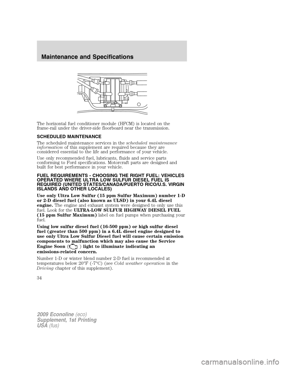
The horizontal fuel conditioner module (HFCM) is located on the
frame-rail under the driver-side floorboard near the transmission.
SCHEDULED MAINTENANCE
The scheduled maintenance services in thescheduled maintenance
informationof this supplement are required because they are
considered essential to the life and performance of your vehicle.
Use only recommended fuel, lubricants, fluids and service parts
conforming to Ford specifications. Motorcraft parts are designed and
built for best performance in your vehicle.
FUEL REQUIREMENTS - CHOOSING THE RIGHT FUEL: VEHICLES
OPERATED WHERE ULTRA LOW SULFUR DIESEL FUEL IS
REQUIRED (UNITED STATES/CANADA/PUERTO RICO/U.S. VIRGIN
ISLANDS AND OTHER LOCALES)
Use only Ultra Low Sulfur (15 ppm Sulfur Maximum) number 1-D
or 2-D diesel fuel (also known as ULSD) in your 6.4L diesel
engine.The engine and exhaust system were designed to only use this
fuel. Look for theULTRA-LOW SULFUR HIGHWAY DIESEL FUEL
(15 ppm Sulfur Maximum)label on fuel pumps when purchasing your
fuel.
Using low sulfur diesel fuel (16-500 ppm) or high sulfur diesel
fuel (greater than 500 ppm) in a 6.4L diesel engine designed to
use only Ultra Low Sulfur Diesel fuel will cause certain emission
components to malfunction which may also cause the Service
Engine Soon(
)light to illuminate indicating an
emissions-related concern.
Number 1-D or winter blend number 2-D fuel is recommended at
temperatures below 20°F (-7°C) (seeCold weather operationin the
Drivingchapter of this supplement).
2009 Econoline(eco)
Supplement, 1st Printing
USA(fus)
Maintenance and Specifications
34
Page 39 of 103
Fuel filler cap
Your fuel tank filler cap has an indexed design with a 1/4 turn on/off
feature.
When fueling your vehicle:
1. Turn the engine off.
2. Carefully turn the filler cap counterclockwise until it spins off.
3. Pull to remove the cap from the fuel filler pipe.
4. To install the cap, align the tabs on the cap with the notches on the
filler pipe.
5. Turn the filler cap clockwise 1/4 of a turn until it clicks at least once.
If you must replace the fuel filler cap, replace it with a fuel filler
cap that is designed for your vehicle. The vehicle warranty may
be void for any damage to the fuel tank or fuel system if the
correct genuine Ford or Motorcraft fuel filler cap is not used.
WARNING:The fuel system may be under pressure. If the fuel
filler cap is venting vapor or if you hear a hissing sound, wait
until it stops before completely removing the fuel filler cap. Otherwise,
fuel may spray out and injure you or others.
WARNING:If you do not use the proper fuel filler cap,
excessive pressure or vacuum in the fuel tank may damage the
fuel system or cause the fuel cap to disengage in a collision, which may
result in possible personal injury.
FUEL FILTER/WATER SEPARATOR
Fuel Conditioner Module (FCM - E-Series)
The vehicle is equipped with a Fuel Conditioning Module (FCM) located
on the driver-side of the vehicle next to the transmission case.
Water should be drained from the
module assembly whenever the
warning light comes on. The WATER
IN FUEL light will come on when
approximately 0.2 pints (100 cc) of water accumulates in the module.
2009 Econoline(eco)
Supplement, 1st Printing
USA(fus)
Maintenance and Specifications
39
Page 40 of 103
Horizontal Fuel Conditioner Module (HFCM - F-Super Duty)
The vehicle is equipped with a Horizontal Fuel Conditioning Module
(HFCM) located on the frame-rail under the driver-side floorboard near
the transmission
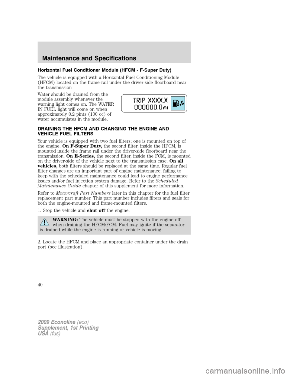
Water should be drained from the
module assembly whenever the
warning light comes on. The WATER
IN FUEL light will come on when
approximately 0.2 pints (100 cc) of
water accumulates in the module.
DRAINING THE HFCM AND CHANGING THE ENGINE AND
VEHICLE FUEL FILTERS
Your vehicle is equipped with two fuel filters; one is mounted on top of
the engine.On F-Super Duty,the second filter, inside the HFCM, is
mounted inside the frame rail under the driver-side floorboard near the
transmission.On E-Series,the second filter, inside the FCM, is mounted
on the driver-side of the vehicle next to the transmission case.On all
vehicles,both filters should be replaced at the same time. Regular fuel
filter changes are an important part of engine maintenance; failing to
keep with the scheduled maintenance could lead to engine performance
issues and/or fuel injection system damage. Refer to theScheduled
Maintenance Guidechapter of this supplement for more information.
Refer toMotorcraft Part Numberslater in this chapter for the fuel filter
replacement part number. This part number includes filters and seals for
both the engine-mounted and frame-mounted filters.
1. Stop the vehicle andshut offthe engine.
WARNING:The vehicle must be stopped with the engine off
when draining the HFCM/FCM. Fuel may ignite if the separator
is drained while the engine is running or vehicle is moving.
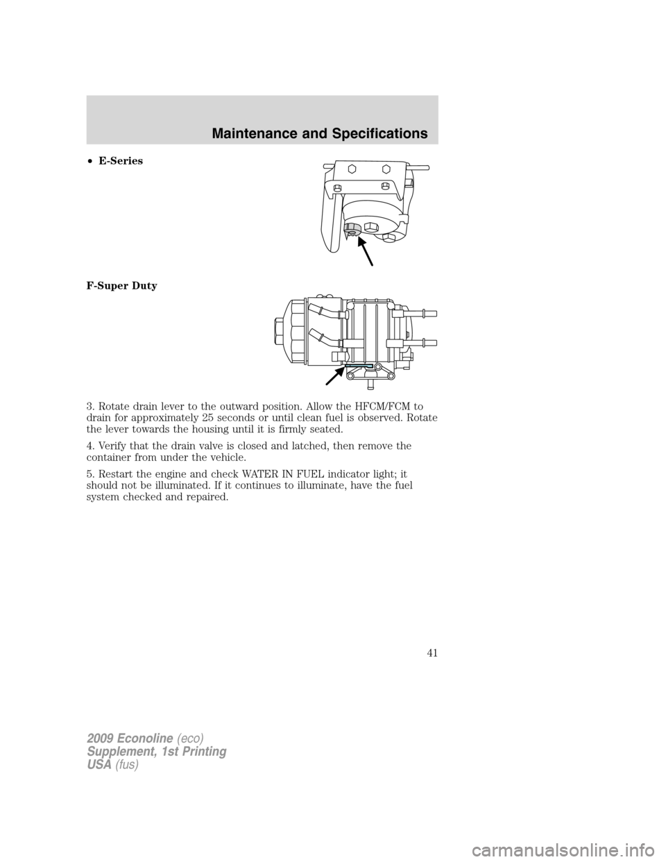
2. Locate the HFCM and place an appropriate container under the drain
port (see illustration).
2009 Econoline(eco)
Supplement, 1st Printing
USA(fus)
Maintenance and Specifications
40
Page 41 of 103
•E-Series
F-Super Duty
3. Rotate drain lever to the outward position. Allow the HFCM/FCM to
drain for approximately 25 seconds or until clean fuel is observed. Rotate
the lever towards the housing until it is firmly seated.
4. Verify that the drain valve is closed and latched, then remove the
container from under the vehicle.
5. Restart the engine and check WATER IN FUEL indicator light; it
should not be illuminated. If it continues to illuminate, have the fuel
system checked and repaired.
2009 Econoline(eco)
Supplement, 1st Printing
USA(fus)
Maintenance and Specifications
41
Page 48 of 103
•use of biodiesel, up to and including 5% Biodiesel (B5)
•use of high sulfur diesel fuel
If you are operating your vehicle under any of these conditions, change
engine oil and filter every 5,000 miles (8,000 km).
AIR FILTER RESTRICTION GAUGE AND AIR FILTER
REPLACEMENT
Air filter restriction gauge:
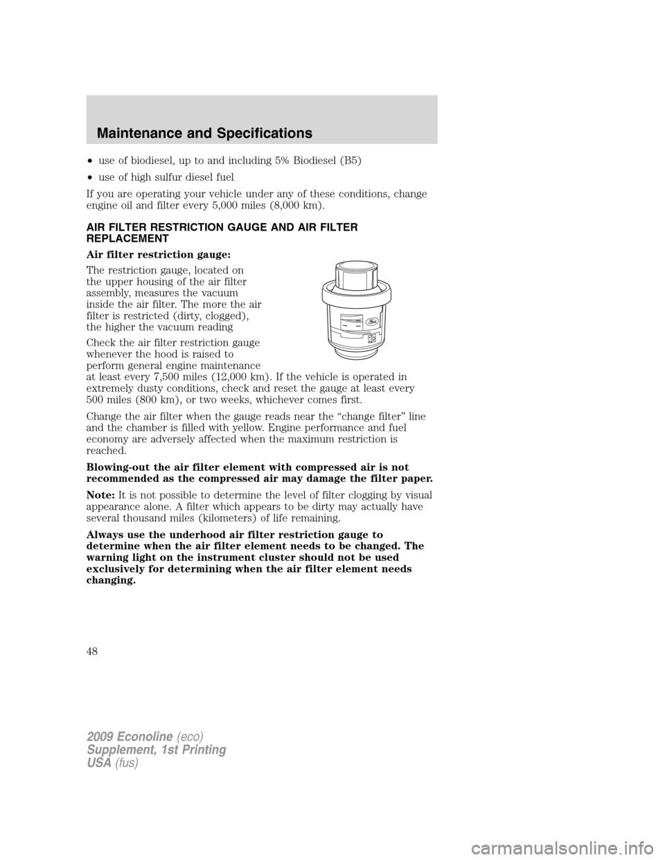
The restriction gauge, located on
the upper housing of the air filter
assembly, measures the vacuum
inside the air filter. The more the air
filter is restricted (dirty, clogged),
the higher the vacuum reading
Check the air filter restriction gauge
whenever the hood is raised to
perform general engine maintenance
at least every 7,500 miles (12,000 km). If the vehicle is operated in
extremely dusty conditions, check and reset the gauge at least every
500 miles (800 km), or two weeks, whichever comes first.
Change the air filter when the gauge reads near the “change filter” line
and the chamber is filled with yellow. Engine performance and fuel
economy are adversely affected when the maximum restriction is
reached.
Blowing-out the air filter element with compressed air is not
recommended as the compressed air may damage the filter paper.
Note:It is not possible to determine the level of filter clogging by visual
appearance alone. A filter which appears to be dirty may actually have
several thousand miles (kilometers) of life remaining.
Always use the underhood air filter restriction gauge to
determine when the air filter element needs to be changed. The
warning light on the instrument cluster should not be used
exclusively for determining when the air filter element needs
changing.
2009 Econoline(eco)
Supplement, 1st Printing
USA(fus)
Maintenance and Specifications
48
Page 49 of 103
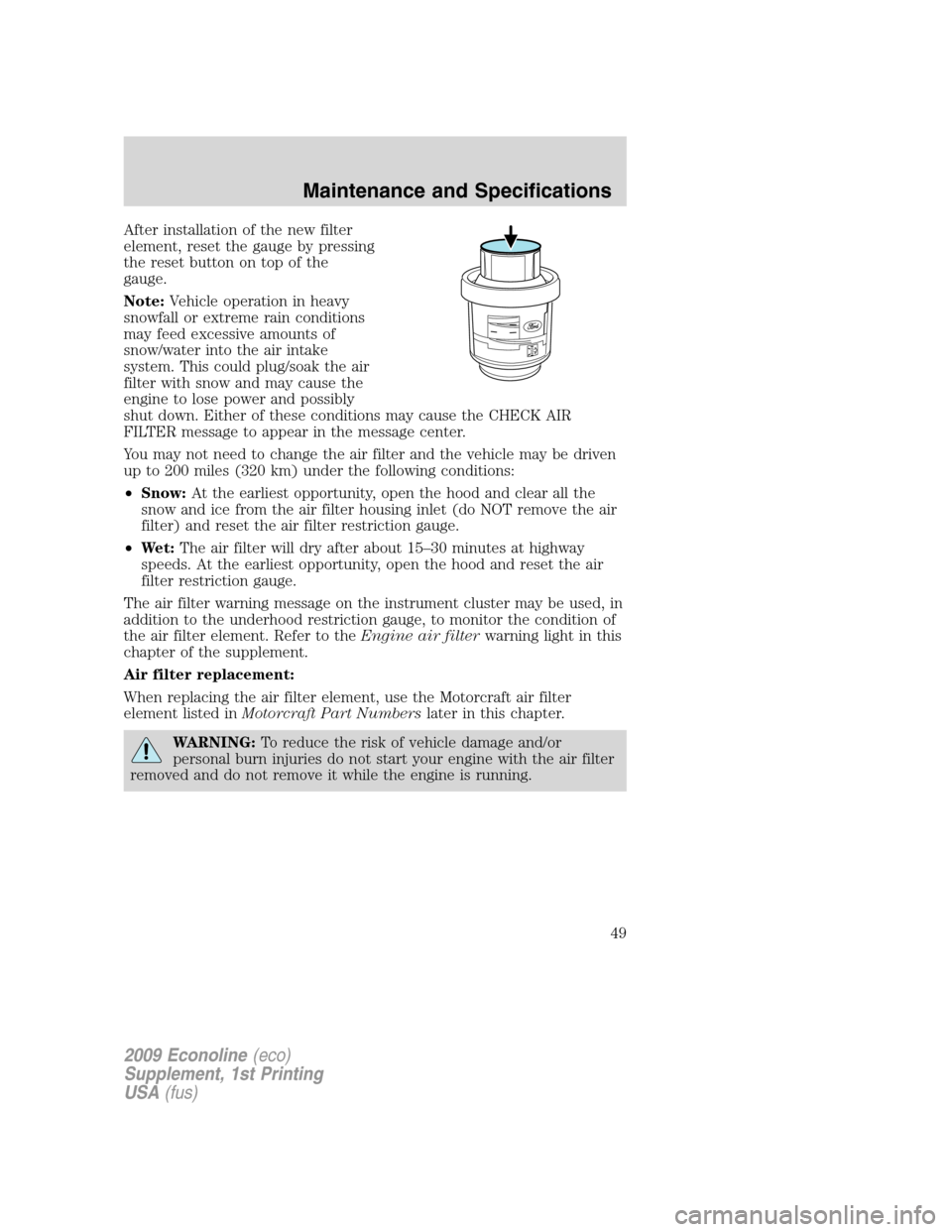
After installation of the new filter
element, reset the gauge by pressing
the reset button on top of the
gauge.
Note:Vehicle operation in heavy
snowfall or extreme rain conditions
may feed excessive amounts of
snow/water into the air intake
system. This could plug/soak the air
filter with snow and may cause the
engine to lose power and possibly
shut down. Either of these conditions may cause the CHECK AIR
FILTER message to appear in the message center.
You may not need to change the air filter and the vehicle may be driven
up to 200 miles (320 km) under the following conditions:
•Snow:At the earliest opportunity, open the hood and clear all the
snow and ice from the air filter housing inlet (do NOT remove the air
filter) and reset the air filter restriction gauge.
•Wet:The air filter will dry after about 15–30 minutes at highway
speeds. At the earliest opportunity, open the hood and reset the air
filter restriction gauge.
The air filter warning message on the instrument cluster may be used, in
addition to the underhood restriction gauge, to monitor the condition of
the air filter element. Refer to theEngine air filterwarning light in this
chapter of the supplement.
Air filter replacement:
When replacing the air filter element, use the Motorcraft air filter
element listed inMotorcraft Part Numberslater in this chapter.
WARNING:To reduce the risk of vehicle damage and/or
personal burn injuries do not start your engine with the air filter
removed and do not remove it while the engine is running.
2009 Econoline(eco)
Supplement, 1st Printing
USA(fus)
Maintenance and Specifications
49
Page 52 of 103
Passive regeneration
In passive regeneration, the exhaust constituents / temperature are at an
appropriate level where some soot can be reduced or oxidized (burned)
thus cleaning the filter. This method occurs naturally as a result of
normal engine operating conditions (at varying levels due to drive
patterns).
Active regeneration
If there is not enough passive regeneration naturally occurring due to
vehicle drive patterns, the engine control system will initiate an active
regeneration. In an active regeneration, the filter is cleaned by raising
the exhaust temperature to a point where the soot is burned away. This
is accomplished through various engine actions which raise the exhaust
temperature in the oxidation catalyst/DPF system to an appropriate high
level where the soot is burned off. After the soot is burned off, the
exhaust temperature and back-pressure (restriction) fall back to normal
levels.
Filter service/maintenance
Over time a slight amount of ash will build up in the DPF which is not
removed during the regeneration process. The DPF may need to be
removed for ash cleaning at approximately 120,000 miles (193,000 km)
or greater (actual mileage can vary greatly depending upon
engine/vehicle operating conditions) and replaced with a new or
remanufactured (ash cleaned) part. The filter may need to be replaced
at approximately 250,000 miles (400,000 km) depending upon
engine/vehicle operating conditions. In both cases the engine control
system will set a service light (
) to inform you to bring the vehicle
to the dealer for service.
If there are any issues with the oxidation catalyst/DPF system a service
light (
or) will be set by the engine control system to inform
you to bring the vehicle into a dealership for service.
Resonator/Tailpipe assembly maintenance
The diesel resonator tail-pipe assembly is a uniquely functioning device
that accompanies the Oxidation Catalyst/DPF assembly. The assembly
serves multiple functions. First it serves as an acoustic device to
attenuate exhaust noise. Second it provides an exit path for the exhaust
from the vehicle. It also is designed to help control the temperature of
the exhaust during DPF regeneration events. The visible holes in each
leg of the twin tip and the holes under the shield just inboard of the
2009 Econoline(eco)
Supplement, 1st Printing
USA(fus)
Maintenance and Specifications
52
Page 55 of 103
•contaminated fuel.
•air in the fuel system, due to loose connections.
•an open or pinched sensor hose.
•low engine oil level.
•wrong fuel or oil viscosity for climactic conditions.
If these checks do not help you correct the engine performance problem
you are experiencing, consult an authorized dealer.
FUELING
WARNING:Do not use starting fluid such as ether or gasoline
in the diesel air intake system. Such fluids can cause immediate
explosive damage to the engine and possible personal injury.
If you fuel your vehicle at a truck stop, you may notice that the fuel
nozzle may shut off every 5–10 seconds. This is due to the flow rates
being designed for larger heavy duty trucks. You may have to fuel at a
slower rate (don’t depress the nozzle trigger fully).
Do not run your diesel vehicle out of fuel as this will allow air to enter
the fuel system which will make restarting difficult. The engine is
designed to run roughly as the fuel tank nears Empty. This is a warning
to the driver to add fuel as soon as possible. Longer engine cranking
time may be required once air is in the fuel system. If air enters the fuel
system (either through running the fuel tank(s) empty or during a fuel
filter change), the engine will self-purge the trapped air once it starts
running. The engine may run roughly and produce white smoke while air
is in the fuel system; this is normal and should stop after a short time.
MINOR TROUBLESHOOTING GUIDE
Air purge procedure
Turn the key on for 30 seconds, then turn off. Repeat procedure four or
five times.
If the engine won’t crank
Turn on the headlights. If the lights are dim, do not go on at all or when
the ignition is turned to START the lights become dim or go out, the
battery connections may be loose or corroded, or the battery may be
discharged. If there is a clicking or stuttering sound coming from the
engine compartment when you turn the key to START, this may also
indicate a loose or corroded battery connection.
2009 Econoline(eco)
Supplement, 1st Printing
USA(fus)
Maintenance and Specifications
55