2009 FORD F350 oil
[x] Cancel search: oilPage 148 of 419
DRAIN WATER SEPARATOR (Diesel engine only)— Displayed
when the water separator has reached a predetermined capacity and
needs to be drained. Refer to your6.0 and 6.4 Liter Power Stroke
Direct Injection Turbo Diesel Owner’s Guide Supplementfor more
information.
STOP SAFELY NOW (Diesel engine only)— Displays and a chime
sounds when the vehicle exhaust system temperature exceeds intended
operating range. If this warning occurs, the engine power is reduced and
the engine will shutdown when the vehicle speed is below 3 mph
(5 km/h).Stop the vehicle as soon as safely possibleand contact
your authorized dealer. Depending on the severity of the
over-temperature condition, the vehicle may or may not restart after
cycling the ignition off. If the vehicle restarts, there may be limited
power, or there could be full function. If the exhaust over-temperature
condition reoccurs the message center will display, STOP SAFELY NOW,
the chime will sound, the engine power will be reduced again and shut
down below 3 mph (5km/h).
ENGINE WARMING PLEASE WAIT XX (Diesel engine only)—
Displayed in extremely cold weather; typically around –15°F (–26°C).
The accelerator pedal will not respond to pressing; this is done so the
engine oil can be properly circulated to avoid engine damage from lack
of lubrication. A timer will begin a countdown from 30 seconds, then OK
TO DRIVE will display once the counter has reached 0 (zero) and the
accelerator pedal will respond to pressing.
OK TO DRIVE (Diesel engine only)— Displayed when the time
counter has reached 0 (zero) and the engine is sufficiently warm enough
to drive in extremely cold weather (refer to the ENGINE WARMING
description mentioned previously).
ENGINE TURNS OFF IN XX (Diesel engine only)— Displayed
when the vehicle is in the final 30 seconds of a countdown to where the
engine will intentionally be turned off by the PCM. The diesel engine
shutdown is a (Regulatory) requirement which may be required of a
particular diesel vehicle for sale in States requiring this feature.
ENGINE TURNED OFF (Diesel engine only)— Displayed after the
30 second countdown.
2009 F-250/350/450/550(f23)
Owners Guide, 3rd Printing
USA(fus)
Driver Controls
148
ProCarManuals.com
Page 149 of 419
DRIVE TO CLEAN EXHAUST FILTER (Diesel engine only)—
Displayed when the engine control module detects the Diesel Particulate
Filter (DPF) is full of particulates and that the vehicle is not being
operated in a manner to allow automatic cleaning. The vehicle operator
will have to drive the vehicle above 30 mph (48 km/h) for at least
20 minutes to clean the DPF. This message will continue to be displayed
until an adequate drive cycle is completed. This message is NORMAL.
Note:Power-Take-Off (PTO) and/or Stationary Elevated Idle (SEIC)
must be disabled in order to initiate Diesel Particulate Filter (DPF)
cleaning.
CLEANING EXHAUST FILTER (Diesel engine only)— Displays
continuously when the vehicle has entered the cleaning mode normally;
or when cleaning the filter after a DRIVE TO CLEAN EXHAUST FILTER
message was previously displayed. When this message is displayed
various engine actions will raise the exhaust temperature in the DPF to
clean the exhaust filter. After the exhaust filter is cleaned, the exhaust
temperature will fall back to normal levels. This message is NORMAL.
WARNING:When the CLEANING EXHAUST FILTER message
appears in the message center do not park near flammable
materials, vapors and structures until filter cleaning is complete.
EXHAUST FILTER DRIVE COMPLETE (Diesel engine only)—
Displayed when the vehicle has completed the adequate drive cycle to
clean the DPF. This message is NORMAL.
WARNING:Do not park, idle, or drive your vehicle in dry grass
or other dry ground cover. The emission system heats up the
engine compartment and exhaust system, which can start a fire.
XX% OIL LIFE CHANGE SOON (Gas engine only)— Displayed
when an oil change will soon be required and shows the percentage of oil
life left.
OIL CHANGE REQUIRED (Gas engine only)— Displayed when the
oil life left reaches 0%, the OIL CHANGE REQUIRED message will be
displayed. OIL LIFE OK displays after you have changed the oil.
2009 F-250/350/450/550(f23)
Owners Guide, 3rd Printing
USA(fus)
Driver Controls
149
ProCarManuals.com
Page 224 of 419
Move a child to a different seating location if the shoulder belt does not
stay positioned on the shoulder during use.
Follow all instructions provided by the manufacturer of the booster seat.
WARNING:Never place, or allow a child to place, the shoulder
belt under a child’s arm or behind the back because it reduces
the protection for the upper part of the body and may increase the risk
of injury or death in a collision.
Child restraint and safety belt maintenance
Inspect the vehicle safety belts and child safety seat systems periodically
to make sure they work properly and are not damaged. Inspect the
vehicle and child seat safety belts to make sure there are no nicks, tears
or cuts. Replace if necessary. All vehicle safety belt assemblies, including
retractors, buckles, front safety belt buckle assemblies, buckle support
assemblies (slide bar-if equipped), shoulder belt height adjusters (if
equipped), shoulder belt guide on seatback (if equipped), child safety
seat LATCH and tether anchors, and attaching hardware, should be
inspected after a collision. Refer to the child restraint manufacturer’s
instructions for additional inspection and maintenance information
specific to the child restraint. Ford Motor Company recommends that all
safety belt assemblies in use in vehicles involved in a collision be
replaced. However, if the collision was minor and an authorized dealer
finds that the belts do not show damage and continue to operate
properly, they do not need to be replaced. Safety belt assemblies not in
use during a collision should also be inspected and replaced if either
damage or improper operation is noted.
For proper care of soiled safety belts, refer toInteriorin theCleaning
chapter.
WARNING:Failure to inspect and if necessary replace the
safety belt assembly or child restraint system under the above
conditions could result in severe personal injuries in the event of a
collision.
2009 F-250/350/450/550(f23)
Owners Guide, 3rd Printing
USA(fus)
Seating and Safety Restraints
224
ProCarManuals.com
Page 313 of 419

•The snow plow prep package includes a unique powertrain control
strategy which is required for diesel engine cooling during highway
driving with the snowplow raised.
Operating the vehicle with the snowplow attached
Do not use your vehicle for snow removal until it has been driven at
least 500 miles (800 km).
The attached snowplow blade restricts airflow to the radiator, and may
cause the engine to run at a higher temperature: Attention to engine
temperature is especially important when outside temperatures are
above freezing. Angle the blade to maximize airflow to the radiator and
monitor engine temperature to determine whether a left or right angle
provides the best performance.
Follow the severe duty schedule in yourscheduled maintenance
informationfor engine oil and transmission fluid change intervals.
Snowplowing with your airbag-equipped vehicle
Your vehicle is equipped with a driver and passenger airbag
Supplemental Restraint System (SRS) The SRS is designed to activate in
certain frontal and offset frontal collisions when the vehicle sustains
sufficient longitudinal deceleration.
Careless or high speed driving while plowing snow which results in
sufficient vehicle decelerations can deploy the airbag. Such driving also
increases the risk of accidents.
WARNING:All occupants of the vehicle, including the driver,
should always properly wear their safety belts, even when an air
bag supplemental restraint system (SRS) is provided.
Never remove or defeat the “tripping mechanisms” designed into the
snow removal equipment by its manufacturer. Doing so may cause
damage to the vehicle and the snow removal equipment as well as
possible airbag deployment.
WARNING:Do not attempt to service, repair, or modify the air
bag supplemental restraint system (SRS) or its fuses. See your
Ford or Lincoln Mercury dealer.
2009 F-250/350/450/550(f23)
Owners Guide, 3rd Printing
USA(fus)
Driving
313
ProCarManuals.com
Page 321 of 419

Fuse/Relay
LocationFuse Amp
RatingProtected Circuits
11 10A Not used (spare)
12 7.5A Power mirror switch, Driver power seat
(Memory)
13 5A Not used (spare)
14 10A Upfitter relay #3 feed
15 10A Climate control head
16 15A Upfitter Relay #4 Feed
17 20A All lock motor feeds
18 20A Heated seat relay feed
19 25A Not used (spare)
20 15A Adjustable pedals, Datalink
21 15A Fog lamp relay feed, Cornering lamps
22 15A Park lamp relay feed
23 15A High beam headlight relay feed
24 20A Horn relay feed
25 10A Power telescoping mirror switch Demand
lamps - underhood and illuminated visor
(battery saver)
26 10A Cluster
27 20A Ignition switch feed, Passenger
compartment fuses 28, 42, 43, 44, and
45, Engine compartment starter relay
coil #57 (Diesel engine), Accessory
shutoff control module (if equipped)
(Diesel engine), Engine compartment
starter relay diode (gasoline engines)
28 5A Radio
29 5A Not used (spare)
30 5A Not used (spare)
31 10A Not used (spare)
32 10A Restraints Control Module (RCM),
Passenger Airbag Deactivation Indicator
2009 F-250/350/450/550(f23)
Owners Guide, 3rd Printing
USA(fus)
Roadside Emergencies
321
ProCarManuals.com
Page 322 of 419
Fuse/Relay
LocationFuse Amp
RatingProtected Circuits
33 10A Trailer tow brake controller, Trailer tow
battery charge relay coil
34 5A Not used (spare)
35 10A Reverse Sensing System (RSS), 4x4
module, 4x4 solenoid, Traction control
switch, Tow/Haul switch (Diesel engine)
36 5A Passive Anti-Theft System (PATS)
transceiver, Cluster control
37 10A Dual automatic or Manual climate
control, PTC control
38 20A Subwoofer
39 20A Radio, Navigation radio and amplifier
40 20A 4x4 module, Satellite radio module,
SYNC
41 15A Radio, Electrochromatic rear view mirror,
Lock switch illumination
42 10A Heated seat relay coil, Upfitter switch
relay coils, Heated mirror relay coil
43 10A Fuel tank selector switch, 4x4 module
44 10A Run customer access feed (PTO)
45 5A Front wiper logic, Blower motor relay
coil
46 7.5A Not used (spare)
47 30A Circuit
BreakerPower windows, Moon roof, Power
Sliding Backlite
48 Relay Delayed accessory
Power distribution box
The power distribution box is located in the engine compartment. The
power distribution box contains high-current fuses that protect your
vehicle’s main electrical systems from overloads.
WARNING:Always disconnect the battery before servicing high
current fuses.
2009 F-250/350/450/550(f23)
Owners Guide, 3rd Printing
USA(fus)
Roadside Emergencies
322
ProCarManuals.com
Page 323 of 419
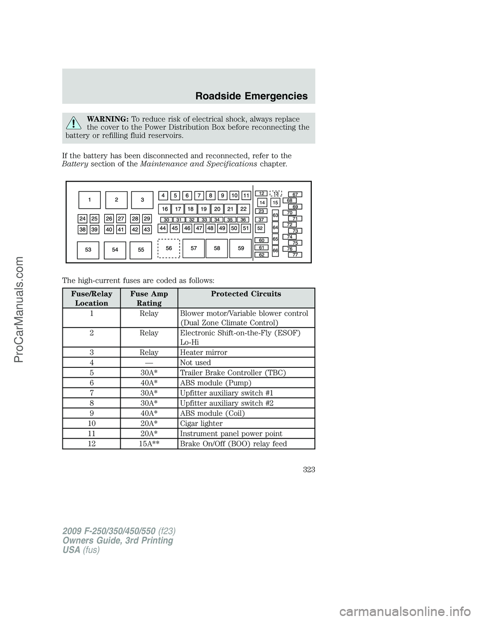
WARNING:To reduce risk of electrical shock, always replace
the cover to the Power Distribution Box before reconnecting the
battery or refilling fluid reservoirs.
If the battery has been disconnected and reconnected, refer to the
Batterysection of theMaintenance and Specificationschapter.
The high-current fuses are coded as follows:
Fuse/Relay
LocationFuse Amp
RatingProtected Circuits
1 Relay Blower motor/Variable blower control
(Dual Zone Climate Control)
2 Relay Electronic Shift-on-the-Fly (ESOF)
Lo-Hi
3 Relay Heater mirror
4 — Not used
5 30A* Trailer Brake Controller (TBC)
6 40A* ABS module (Pump)
7 30A* Upfitter auxiliary switch #1
8 30A* Upfitter auxiliary switch #2
9 40A* ABS module (Coil)
10 20A* Cigar lighter
11 20A* Instrument panel power point
12 15A** Brake On/Off (BOO) relay feed
2009 F-250/350/450/550(f23)
Owners Guide, 3rd Printing
USA(fus)
Roadside Emergencies
323
ProCarManuals.com
Page 324 of 419
Fuse/Relay
LocationFuse Amp
RatingProtected Circuits
13 5A** Brake switch, Brake switch relay coil,
SJB module, 4x4 module
14 — Not used
15 — Not used
16 Relay A/C clutch
17 Relay Wipers
18 Relay Fuel Pump Driver Module (FPDM),
Fuel injectors (Gasoline engines),
Diesel Fuel Control Module (DFCM)
(Diesel engine)
19 Relay Back-up lamps, Reverse Sensing
System (RSS), Engine compartment
fuse 63
20 Relay Trailer stop/turn (Left)
21 Relay Trailer stop/turn (Right)
22 Relay Stop lamps, Center High-Mounted
Stop Lamp (CHMSL), TBC, Customer
access
23 15A** Heater mirror, Heated spotted mirror
24 40A* Blower motor relay
25 — Not used
26 30A* ESOF relay lo-hi
27 50A* Glow Plug Control Module (GPCM) #1
(Diesel engine only)
28 20A* Heated mirror relay
29 30A* Passenger power seat
30 10A** A/C clutch relay
31 15A** Power fold mirror relay
32 20A** Fuel pump relay
33 20A** Back-up lamp relay
34 25A** Trailer stop/turn relay
35 5A** ESOF relay coils
2009 F-250/350/450/550(f23)
Owners Guide, 3rd Printing
USA(fus)
Roadside Emergencies
324
ProCarManuals.com