2009 FORD F250 brake
[x] Cancel search: brakePage 231 of 419
under-inflation of the tires, improper tires (load range, size, or type), or
vehicle modifications such as lift-kits. In the event that your vehicle
experiences shimmy, you should slowly reduce speed by either lifting off
the accelerator pedal or lightly applying the brakes. The shimmy will
cease as the vehicle speed decreases.
Maximum Permissible Inflation Pressureis the tire manufacturer’s
maximum permissible pressure and/or the pressure at which the
maximum load can be carried by the tire. This pressure is normally
higher than the manufacturer’s recommended cold inflation pressure
which can be found on the Safety Compliance Certification Label or Tire
Label which is located on the B-Pillar or the edge of the driver’s door.
The cold inflation pressure should never be set lower than the
recommended pressure on the Safety Compliance Certification Label or
Tire Label.
When weather temperature changes occur, tire inflation pressures also
change. A 10°F (6°C) temperature drop can cause a corresponding drop
of 1 psi (7 kPa) in inflation pressure. Check your tire pressures
frequently and adjust them to the proper pressure which can be found
on the Safety Compliance Certification Label or Tire Label.
To check the pressure in your tire(s):
1. Make sure the tires are cool, meaning they are not hot from driving
even a mile.
If you are checking tire pressure when the tire is hot, (i.e. driven more
than 1 mile [1.6 km]), never “bleed” or reduce air pressure. The tires are
hot from driving and it is normal for pressures to increase above
recommended cold pressures. A hot tire at or below recommended cold
inflation pressure could be significantly under-inflated.
Note:If you have to drive a distance to get air for your tire(s), check
and record the tire pressure first and add the appropriate air pressure
when you get to the pump. It is normal for tires to heat up and the air
pressure inside to go up as you drive.
2. Remove the cap from the valve on one tire, then firmly press the tire
gauge onto the valve and measure the pressure.
3. Add enough air to reach the recommended air pressure.
Note:If you overfill the tire, release air by pushing on the metal stem in
the center of the valve. Then recheck the pressure with your tire gauge.
4. Replace the valve cap.
5. Repeat this procedure for each tire, including the spare.
2009 F-250/350/450/550(f23)
Owners Guide, 3rd Printing
USA(fus)
Tires, Wheels and Loading
231
Page 252 of 419
and remain on for approximately five (5) seconds. If the light does not
illuminate, the tool needs to be replaced.
TPMS reset tips:
•To reduce the chances of interference from another vehicle, TPMS
reset should be performed at least three feet (one meter) away from
another Ford Motor Company vehicle undergoing the TPMS reset
procedure at the same time.
•Do not wait more than two (2) minutes between resetting each tire
sensor or the system will timeout and the entire procedure will have
to be repeated on all four wheels.
•A double horn chirp indicates the need to repeat the procedure.
TPMS reset procedure
It is recommended that you read the entire procedure before attempting.
Note:To enter the reset mode, Steps 1–6 MUST be completed within
60 seconds.
1. Place the ignition in the off position and keep the key in the ignition.
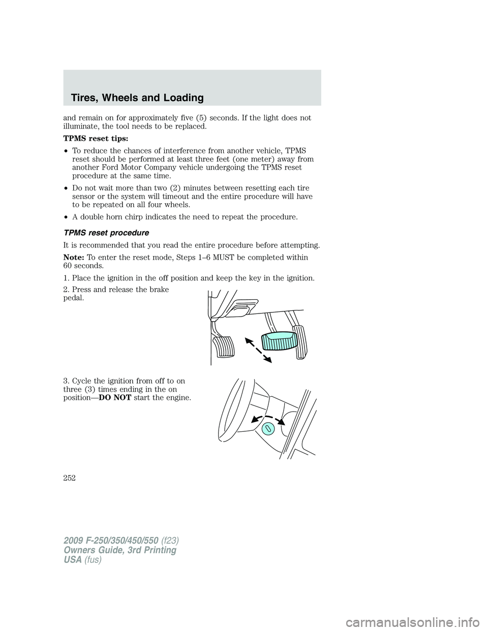
2. Press and release the brake
pedal.
3. Cycle the ignition from off to on
three (3) times ending in the on
position—DO NOTstart the engine.
2009 F-250/350/450/550(f23)
Owners Guide, 3rd Printing
USA(fus)
Tires, Wheels and Loading
252
Page 253 of 419
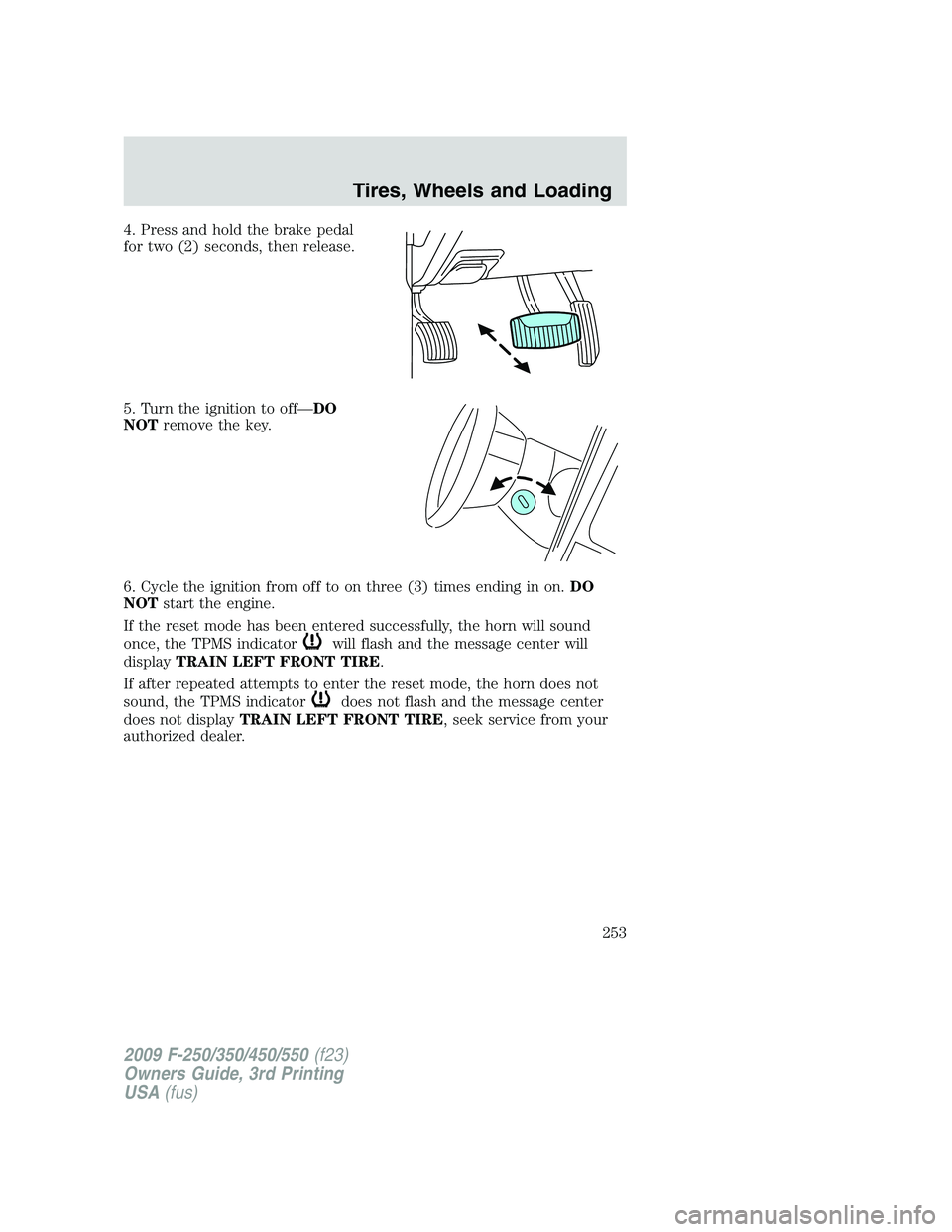
4. Press and hold the brake pedal
for two (2) seconds, then release.
5. Turn the ignition to off—DO
NOTremove the key.
6. Cycle the ignition from off to on three (3) times ending in on.DO
NOTstart the engine.
If the reset mode has been entered successfully, the horn will sound
once, the TPMS indicator
will flash and the message center will
displayTRAIN LEFT FRONT TIRE.
If after repeated attempts to enter the reset mode, the horn does not
sound, the TPMS indicator
does not flash and the message center
does not displayTRAIN LEFT FRONT TIRE, seek service from your
authorized dealer.
2009 F-250/350/450/550(f23)
Owners Guide, 3rd Printing
USA(fus)
Tires, Wheels and Loading
253
Page 255 of 419
10. Perform Steps 8 and 9 on the right front tire, right rear tire and
finally the left rear tire. Training is complete after the horn sounds for
the last tire trained (left rear tire) and the message center displays:
TRAINING COMPLETE.
Turn the ignition to off. If two short horn beeps are heard, the reset
procedure was unsuccessful and must be repeated.
If after repeating the procedure and two short beeps are heard when the
ignition is turned to off, seek assistance from your authorized dealer.
SNOW TIRES AND CHAINS
WARNING:Snow tires must be the same size, load index, speed
rating as those originally provided by Ford. Use of any tire or
wheel not recommended by Ford can affect the safety and
performance of your vehicle, which could result in an increased risk of
loss of vehicle control, vehicle rollover, personal injury and death.
Additionally, the use of non-recommended tires and wheels could
cause steering, suspension, axle or transfer case/power transfer unit
failure.
Note:Do not use snow chains on vehicles with 20 inch wheels and tires.
The tires on your vehicle have all weather treads to provide traction in
rain and snow. However, in some climates, you may need to use snow
tires and chains. If you need to use chains, it is recommended that steel
wheels (of the same size and specifications) be used, as chains may chip
aluminum wheels.
Follow these guidelines when using snow tires and chains:
•Use only SAE Class S chains.
•Install chains securely, verifying that the chains do not touch any
wiring, brake lines or fuel lines.
•Drive cautiously. If you hear the chains rub or bang against your
vehicle, stop and re-tighten the chains. If this does not work, remove
the chains to prevent damage to your vehicle.
•If possible, avoid fully loading your vehicle.
•Remove the tire chains when they are no longer needed. Do not use
tire chains on dry roads.
•The suspension insulation and bumpers will help prevent vehicle
damage. Do not remove these components from your vehicle when
using snow tires and chains.
2009 F-250/350/450/550(f23)
Owners Guide, 3rd Printing
USA(fus)
Tires, Wheels and Loading
255
Page 259 of 419
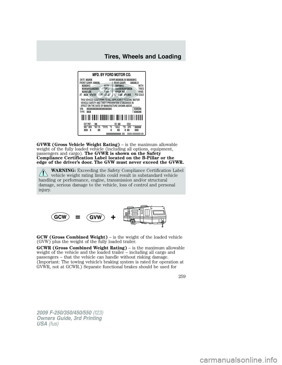
GVWR (Gross Vehicle Weight Rating)– is the maximum allowable
weight of the fully loaded vehicle (including all options, equipment,
passengers and cargo).The GVWR is shown on the Safety
Compliance Certification Label located on the B-Pillar or the
edge of the driver’s door. The GVW must never exceed the GVWR.
WARNING:Exceeding the Safety Compliance Certification Label
vehicle weight rating limits could result in substandard vehicle
handling or performance, engine, transmission and/or structural
damage, serious damage to the vehicle, loss of control and personal
injury.
GCW (Gross Combined Weight)– is the weight of the loaded vehicle
(GVW) plus the weight of the fully loaded trailer.
GCWR (Gross Combined Weight Rating)– is the maximum allowable
weight of the vehicle and the loaded trailer – including all cargo and
passengers – that the vehicle can handle without risking damage.
(Important: The towing vehicle’s braking system is rated for operation at
GVWR, not at GCWR.) Separate functional brakes should be used for
2009 F-250/350/450/550(f23)
Owners Guide, 3rd Printing
USA(fus)
Tires, Wheels and Loading
259
Page 263 of 419
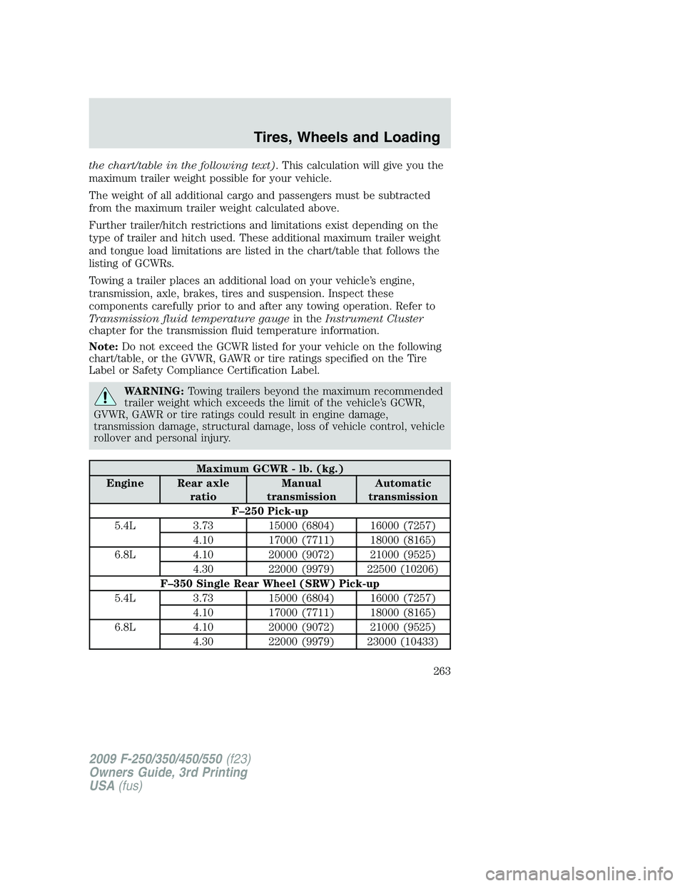
the chart/table in the following text). This calculation will give you the
maximum trailer weight possible for your vehicle.
The weight of all additional cargo and passengers must be subtracted
from the maximum trailer weight calculated above.
Further trailer/hitch restrictions and limitations exist depending on the
type of trailer and hitch used. These additional maximum trailer weight
and tongue load limitations are listed in the chart/table that follows the
listing of GCWRs.
Towing a trailer places an additional load on your vehicle’s engine,
transmission, axle, brakes, tires and suspension. Inspect these
components carefully prior to and after any towing operation. Refer to
Transmission fluid temperature gaugein theInstrument Cluster
chapter for the transmission fluid temperature information.
Note:Do not exceed the GCWR listed for your vehicle on the following
chart/table, or the GVWR, GAWR or tire ratings specified on the Tire
Label or Safety Compliance Certification Label.
WARNING:Towing trailers beyond the maximum recommended
trailer weight which exceeds the limit of the vehicle’s GCWR,
GVWR, GAWR or tire ratings could result in engine damage,
transmission damage, structural damage, loss of vehicle control, vehicle
rollover and personal injury.
Maximum GCWR - lb. (kg.)
Engine Rear axle
ratioManual
transmissionAutomatic
transmission
F–250 Pick-up
5.4L 3.73 15000 (6804) 16000 (7257)
4.10 17000 (7711) 18000 (8165)
6.8L 4.10 20000 (9072) 21000 (9525)
4.30 22000 (9979) 22500 (10206)
F–350 Single Rear Wheel (SRW) Pick-up
5.4L 3.73 15000 (6804) 16000 (7257)
4.10 17000 (7711) 18000 (8165)
6.8L 4.10 20000 (9072) 21000 (9525)
4.30 22000 (9979) 23000 (10433)
2009 F-250/350/450/550(f23)
Owners Guide, 3rd Printing
USA(fus)
Tires, Wheels and Loading
263
Page 267 of 419
2. Measure the height of a reference point on the front and rear bumpers
at the center of the vehicle.
3. Attach the trailer to the vehicle and adjust the hitch equalizers so that
the front bumper height is within
1�2inch (13 mm) of the reference
point. After proper adjustment, the rear bumper should be no higher
than in Step 2.
WARNING:Do not adjust a weight distributing hitch to any
position where the rear bumper of the vehicle is higher than it
was before attaching the trailer. Doing so will defeat the function of
the weight distributing hitch, which may cause unpredictable handling,
and could result in serious personal injury.
Safety chains
Always connect the trailer’s safety chains to the frame or hook retainers
of the vehicle hitch. To connect the trailer’s safety chains, cross the
chains under the trailer tongue and allow slack for turning corners.
If you use a rental trailer, follow the instructions that the rental agency
gives to you.
Do not attach safety chains to the bumper.
Trailer brakes
Electric brakes and manual, automatic or surge-type trailer brakes are
safe if installed properly and adjusted to the manufacturer’s
specifications. The trailer brakes must meet local and Federal
regulations.
WARNING:If you own a trailer with a hydraulic brake system,
do not connect the trailer’s hydraulic brake system directly to
your vehicle’s brake system. The vehicle’s brake system is only
designed to carry the appropriate amount of brake fluid for the vehicle
alone. Connecting a hydraulic trailer braking system could adversely
affect your vehicle’s braking performance.
The braking system of the tow vehicle is rated for operation at the
GVWR not GCWR.
Integrated trailer brake controller (if equipped)
Your vehicle may be equipped with a fully integrated electronic Trailer
Brake Controller (TBC). When used properly, the TBC helps ensure
2009 F-250/350/450/550(f23)
Owners Guide, 3rd Printing
USA(fus)
Tires, Wheels and Loading
267
Page 268 of 419
smooth and effective trailer braking by powering the trailer’s electric
brakes with a proportional output based on the towing vehicle’s brake
pressure.
WARNING:The Ford TBC has only been verified to be
compatible with trailers having electric-actuated drum brakes
(one to four axles) and not hydraulic surge or electric-over-hydraulic
types. It is the responsibility of the customer to ensure that the trailer
brakes are adjusted appropriately, functioning normally and all electric
connections are properly made.
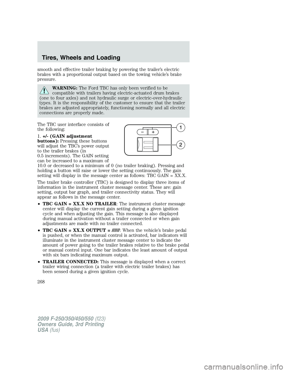
The TBC user interface consists of
the following:
1.+/- (GAIN adjustment
buttons):Pressing these buttons
will adjust the TBC’s power output
to the trailer brakes (in
0.5 increments). The GAIN setting
can be increased to a maximum of
10.0 or decreased to a minimum of 0 (no trailer braking). Pressing and
holding a button will raise or lower the setting continuously. The gain
setting will display in the message center as follows: TBC GAIN = XX.X.
The trailer brake controller (TBC) is designed to display three items of
information in the instrument cluster message center. These are: gain
setting, output bar graph, and trailer connectivity status. They will
appear as follows in the message center.
•TBC GAIN = XX.X NO TRAILER: The instrument cluster message
center will display the current gain setting during a given ignition
cycle and when adjusting the gain. This message is also displayed
during manual activation without a trailer connected or when gain
adjustments are made with no trailer connected.
•TBC GAIN = XX.X OUTPUT = //////: When the vehicle’s brake pedal
is pushed, or when the manual control is activated, bar indicators will
illuminate in the instrument cluster message center to indicate the
amount of power going to the trailer brakes relative to the brake pedal
or manual control input. One bar indicates the least amount of output
with six bars indicating maximum output.
•TRAILER CONNECTED:This message is displayed when a correct
trailer wiring connection (a trailer with electric trailer brakes) has
been sensed during a given ignition cycle.
2009 F-250/350/450/550(f23)
Owners Guide, 3rd Printing
USA(fus)
Tires, Wheels and Loading
268