Page 320 of 419
The fuses are coded as follows.
Fuse/Relay
LocationFuse Amp
RatingProtected Circuits
1 30A Not used (spare)
2 15A Not used (spare)
3 15A Family Entertainment System (FES)
4 30A Not used (spare)
5 10A Keypad illumination, Brake-Shift
Interlock (BSI), SPBJB
6 20A Turn signals
7 10A Left headlamp (Low beam)
8 10A Right headlamp (Low beam)
9 15A Interior lighting, Lighted running boards
10 15A Cargo lamp, Puddle lamp, Switch
backlight
2009 F-250/350/450/550(f23)
Owners Guide, 3rd Printing
USA(fus)
Roadside Emergencies
320
Page 322 of 419

Fuse/Relay
LocationFuse Amp
RatingProtected Circuits
33 10A Trailer tow brake controller, Trailer tow
battery charge relay coil
34 5A Not used (spare)
35 10A Reverse Sensing System (RSS), 4x4
module, 4x4 solenoid, Traction control
switch, Tow/Haul switch (Diesel engine)
36 5A Passive Anti-Theft System (PATS)
transceiver, Cluster control
37 10A Dual automatic or Manual climate
control, PTC control
38 20A Subwoofer
39 20A Radio, Navigation radio and amplifier
40 20A 4x4 module, Satellite radio module,
SYNC
41 15A Radio, Electrochromatic rear view mirror,
Lock switch illumination
42 10A Heated seat relay coil, Upfitter switch
relay coils, Heated mirror relay coil
43 10A Fuel tank selector switch, 4x4 module
44 10A Run customer access feed (PTO)
45 5A Front wiper logic, Blower motor relay
coil
46 7.5A Not used (spare)
47 30A Circuit
BreakerPower windows, Moon roof, Power
Sliding Backlite
48 Relay Delayed accessory
Power distribution box
The power distribution box is located in the engine compartment. The
power distribution box contains high-current fuses that protect your
vehicle’s main electrical systems from overloads.
WARNING:Always disconnect the battery before servicing high
current fuses.
2009 F-250/350/450/550(f23)
Owners Guide, 3rd Printing
USA(fus)
Roadside Emergencies
322
Page 323 of 419
WARNING:To reduce risk of electrical shock, always replace
the cover to the Power Distribution Box before reconnecting the
battery or refilling fluid reservoirs.
If the battery has been disconnected and reconnected, refer to the
Batterysection of theMaintenance and Specificationschapter.
The high-current fuses are coded as follows:
Fuse/Relay
LocationFuse Amp
RatingProtected Circuits
1 Relay Blower motor/Variable blower control
(Dual Zone Climate Control)
2 Relay Electronic Shift-on-the-Fly (ESOF)
Lo-Hi
3 Relay Heater mirror
4 — Not used
5 30A* Trailer Brake Controller (TBC)
6 40A* ABS module (Pump)
7 30A* Upfitter auxiliary switch #1
8 30A* Upfitter auxiliary switch #2
9 40A* ABS module (Coil)
10 20A* Cigar lighter
11 20A* Instrument panel power point
12 15A** Brake On/Off (BOO) relay feed
2009 F-250/350/450/550(f23)
Owners Guide, 3rd Printing
USA(fus)
Roadside Emergencies
323
Page 324 of 419

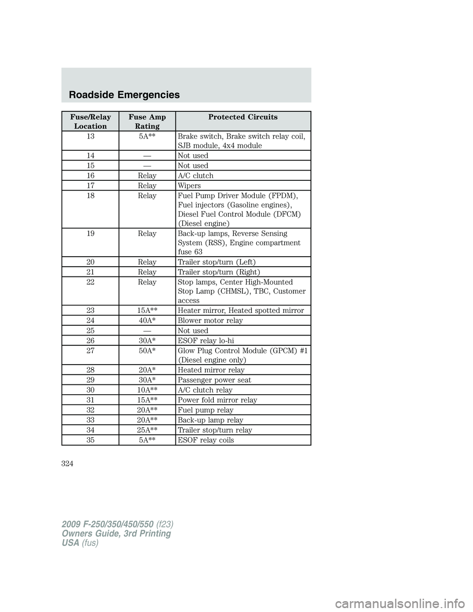
Fuse/Relay
LocationFuse Amp
RatingProtected Circuits
13 5A** Brake switch, Brake switch relay coil,
SJB module, 4x4 module
14 — Not used
15 — Not used
16 Relay A/C clutch
17 Relay Wipers
18 Relay Fuel Pump Driver Module (FPDM),
Fuel injectors (Gasoline engines),
Diesel Fuel Control Module (DFCM)
(Diesel engine)
19 Relay Back-up lamps, Reverse Sensing
System (RSS), Engine compartment
fuse 63
20 Relay Trailer stop/turn (Left)
21 Relay Trailer stop/turn (Right)
22 Relay Stop lamps, Center High-Mounted
Stop Lamp (CHMSL), TBC, Customer
access
23 15A** Heater mirror, Heated spotted mirror
24 40A* Blower motor relay
25 — Not used
26 30A* ESOF relay lo-hi
27 50A* Glow Plug Control Module (GPCM) #1
(Diesel engine only)
28 20A* Heated mirror relay
29 30A* Passenger power seat
30 10A** A/C clutch relay
31 15A** Power fold mirror relay
32 20A** Fuel pump relay
33 20A** Back-up lamp relay
34 25A** Trailer stop/turn relay
35 5A** ESOF relay coils
2009 F-250/350/450/550(f23)
Owners Guide, 3rd Printing
USA(fus)
Roadside Emergencies
324
Page 327 of 419

CHANGING A FLAT TIRE
If you get a flat tire while driving:
•do not brake heavily.
•gradually decrease the vehicle’s speed.
•hold the steering wheel firmly.
•slowly move to a safe place on the side of the road.
Your vehicle may be equipped with a conventional spare tire that is
different in one or more of the following: type, brand, size, speed rating
and tread design. If this is the case, this dissimilar spare tire is still rated
for your vehicle loads (GAWR and GVWR).Temporary spare tires are not
equipped with Tire Pressure Monitor System (TPMS) sensors if the
system is present.
WARNING:The use of tire sealant may damage your Tire
Pressure Monitoring System (if equipped) and should not be
used.
WARNING:If your vehicle is equipped with a Tire Pressure
Monitoring System, refer toTire Pressure Monitoring System
in theTires, Wheels and Loadingchapter for more information. If the
tire pressure monitor sensor becomes damaged, it will no longer
function.
Dissimilar spare tire/wheel information
WARNING:Failure to follow these guidelines could result in an
increased risk of loss of vehicle control, injury or death.
If you have a dissimilar spare tire/wheel, then it is intended for
temporary use only. This means that if you need to use it, you should
replace it as soon as possible with a road tire/wheel that is the same size
and type as the road tires and wheels that were originally provided by
Ford. If the dissimilar spare tire or wheel is damaged, it should be
replaced rather than repaired.
A dissimilar spare tire/wheel is defined as a spare tire and/or wheel that
is different in brand, size or appearance from the road tires and wheels
and can be one of three types:
1.T-type mini-spare:This spare tire begins with the letter “T” for tire
size and may have “Temporary Use Only” molded in the sidewall
2009 F-250/350/450/550(f23)
Owners Guide, 3rd Printing
USA(fus)
Roadside Emergencies
327
Page 330 of 419

•Tow a trailer
•Use snow chains on the end of the vehicle with the temporary spare
tire
•Use more than one temporary spare tire at a time
Use of a temporary spare tire at any one wheel location can lead to
impairment of the following:
•Handling, stability and braking performance
•Comfort and noise
•Ground clearance and parking at curbs
•Winter weather driving capability
•Wet weather driving capability
Stopping and securing the vehicle
WARNING:To help prevent the vehicle from moving when you
change a tire, be sure the parking brake is set, then block (in
both directions) the wheel that is diagonally opposite to the tire being
changed.
Refer to the instruction sheet (located in the glove box) for detailed tire
change instructions.
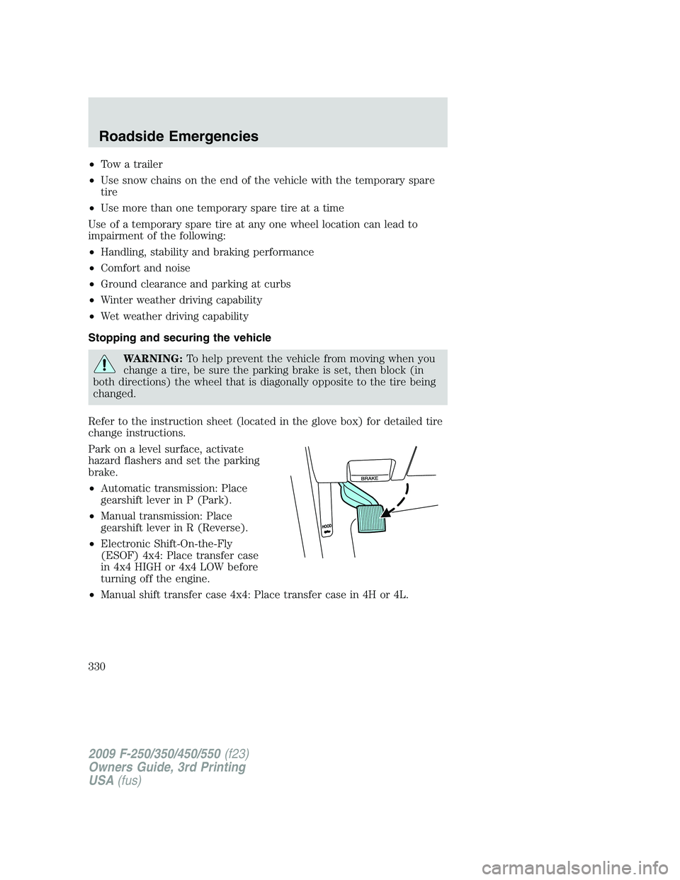
Park on a level surface, activate
hazard flashers and set the parking
brake.
•Automatic transmission: Place
gearshift lever in P (Park).
•Manual transmission: Place
gearshift lever in R (Reverse).
•Electronic Shift-On-the-Fly
(ESOF) 4x4: Place transfer case
in 4x4 HIGH or 4x4 LOW before
turning off the engine.
•Manual shift transfer case 4x4: Place transfer case in 4H or 4L.
2009 F-250/350/450/550(f23)
Owners Guide, 3rd Printing
USA(fus)
Roadside Emergencies
330
Page 332 of 419

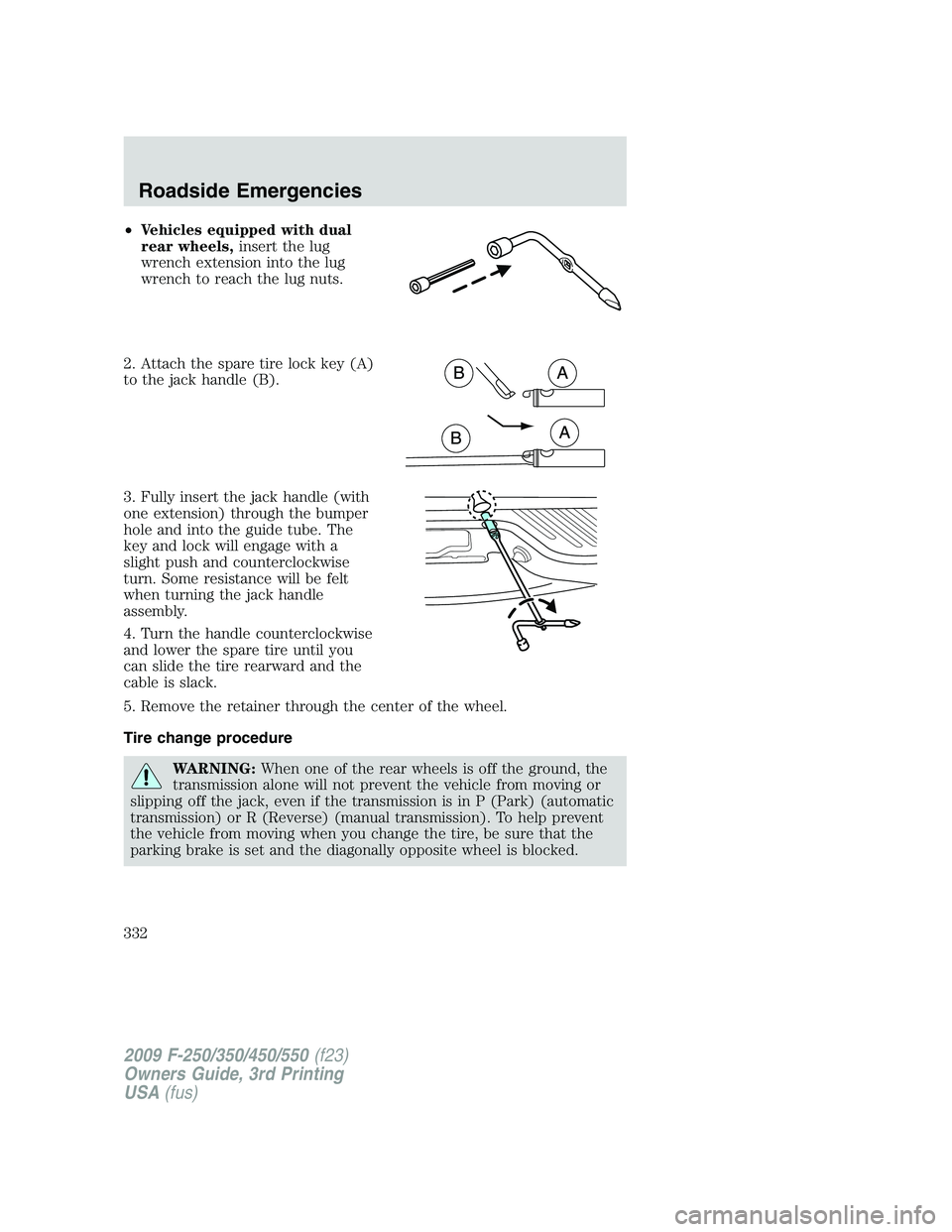
•Vehicles equipped with dual
rear wheels,insert the lug
wrench extension into the lug
wrench to reach the lug nuts.
2. Attach the spare tire lock key (A)
to the jack handle (B).
3. Fully insert the jack handle (with
one extension) through the bumper
hole and into the guide tube. The
key and lock will engage with a
slight push and counterclockwise
turn. Some resistance will be felt
when turning the jack handle
assembly.
4. Turn the handle counterclockwise
and lower the spare tire until you
can slide the tire rearward and the
cable is slack.
5. Remove the retainer through the center of the wheel.
Tire change procedure
WARNING:When one of the rear wheels is off the ground, the
transmission alone will not prevent the vehicle from moving or
slipping off the jack, even if the transmission is in P (Park) (automatic
transmission) or R (Reverse) (manual transmission). To help prevent
the vehicle from moving when you change the tire, be sure that the
parking brake is set and the diagonally opposite wheel is blocked.
2009 F-250/350/450/550(f23)
Owners Guide, 3rd Printing
USA(fus)
Roadside Emergencies
332
Page 333 of 419

WARNING:To prevent the vehicle from moving when you
change a tire, be sure the parking brake is set, then block (in
both directions) the wheel that is diagonally opposite (other side and
end of the vehicle) to the tire being changed.
WARNING:If the vehicle slips off the jack, you or someone else
could be seriously injured.
WARNING:Do not attempt to change a tire on the side of the
vehicle close to moving traffic. Pull far enough off the road to
avoid the danger of being hit when operating the jack or changing the
wheel.
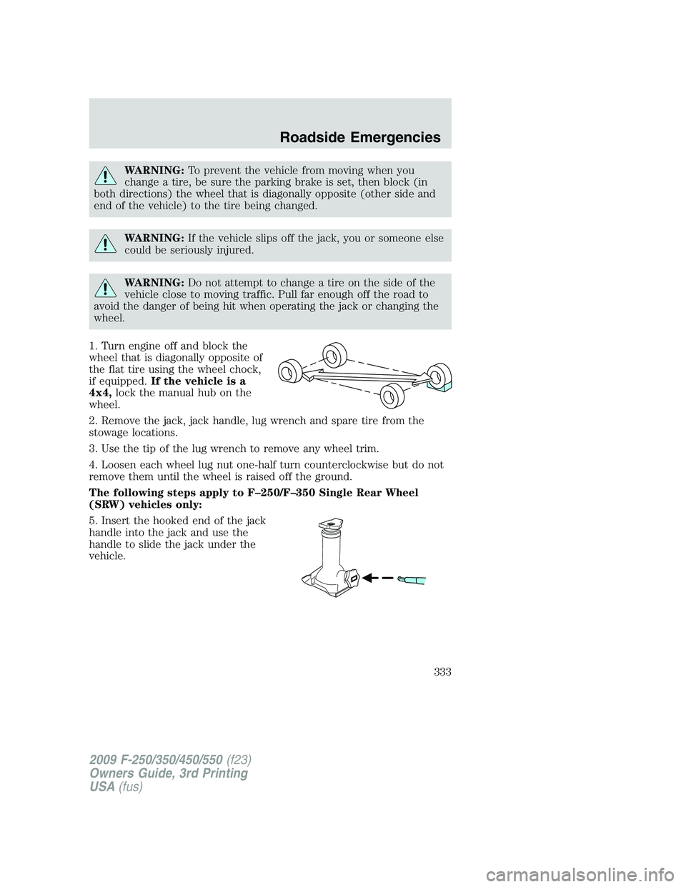
1. Turn engine off and block the
wheel that is diagonally opposite of
the flat tire using the wheel chock,
if equipped.If the vehicle is a
4x4,lock the manual hub on the
wheel.
2. Remove the jack, jack handle, lug wrench and spare tire from the
stowage locations.
3. Use the tip of the lug wrench to remove any wheel trim.
4. Loosen each wheel lug nut one-half turn counterclockwise but do not
remove them until the wheel is raised off the ground.
The following steps apply to F–250/F–350 Single Rear Wheel
(SRW) vehicles only:
5. Insert the hooked end of the jack
handle into the jack and use the
handle to slide the jack under the
vehicle.
2009 F-250/350/450/550(f23)
Owners Guide, 3rd Printing
USA(fus)
Roadside Emergencies
333