Page 74 of 136

Fuse/Relay
LocationFuse Amp
RatingProtected Circuits
3 20A* A/C clutch relay coil, Mass Air
Flow Sensor (MAFS) with Intake
Air Temperature (IAT), Vapor
Management Valve, Engine
Heated Exhaust Gas Oxygen
(HEGO) sensor #11, HEGO #21,
Catalyst Monitor Sensor (CMS)
4 5A* Powertrain Control Module (PCM)
memory
5 20A* PCM power
6 20A* Park lamp feeds, Instrument
Panel (IP) fuse #41, Warning
chime module, Trailer tow
running lamp relay coil, IP
dimmer module
7 20A* Ignition coils, Radio capacitors
8 10A* Stoplamp switch (logic): Power
brake assist module***, Speed
control module, PCM, Anti-lock
Brake System (ABS) module,
Brake shift interlock actuator
9 10A* Starter main relay coil, Starter
ground relay coil
10 20A* Daytime Running Lamps (DRL)
11 20A* Fuel pump relay coil, PCM power
12 25A* Trailer tow back-up lamps feed, IP
- backup lamp feed
13 30A** Trailer tow electric brake
controller feed
14 60A** IP battery feed (fuse #9, 15, 21)
15 20A Trailer tow park lamps
16 60A** ABS module
17 20A** Horn feed
2009 Motorhome(mot)
Supplement, 1st Printing
USA(fus)
Roadside Emergencies
74
Page 75 of 136
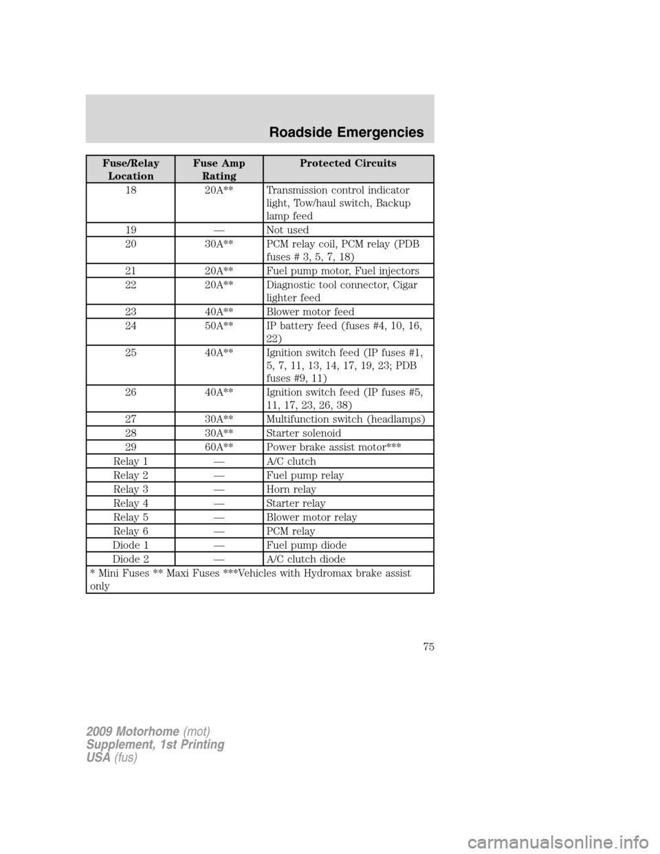
Fuse/Relay
LocationFuse Amp
RatingProtected Circuits
18 20A** Transmission control indicator
light, Tow/haul switch, Backup
lamp feed
19 — Not used
20 30A** PCM relay coil, PCM relay (PDB
fuses#3,5,7,18)
21 20A** Fuel pump motor, Fuel injectors
22 20A** Diagnostic tool connector, Cigar
lighter feed
23 40A** Blower motor feed
24 50A** IP battery feed (fuses #4, 10, 16,
22)
25 40A** Ignition switch feed (IP fuses #1,
5, 7, 11, 13, 14, 17, 19, 23; PDB
fuses #9, 11)
26 40A** Ignition switch feed (IP fuses #5,
11, 17, 23, 26, 38)
27 30A** Multifunction switch (headlamps)
28 30A** Starter solenoid
29 60A** Power brake assist motor***
Relay 1 — A/C clutch
Relay 2 — Fuel pump relay
Relay 3 — Horn relay
Relay 4 — Starter relay
Relay 5 — Blower motor relay
Relay 6 — PCM relay
Diode 1 — Fuel pump diode
Diode 2 — A/C clutch diode
* Mini Fuses ** Maxi Fuses ***Vehicles with Hydromax brake assist
only
2009 Motorhome(mot)
Supplement, 1st Printing
USA(fus)
Roadside Emergencies
75
Page 76 of 136
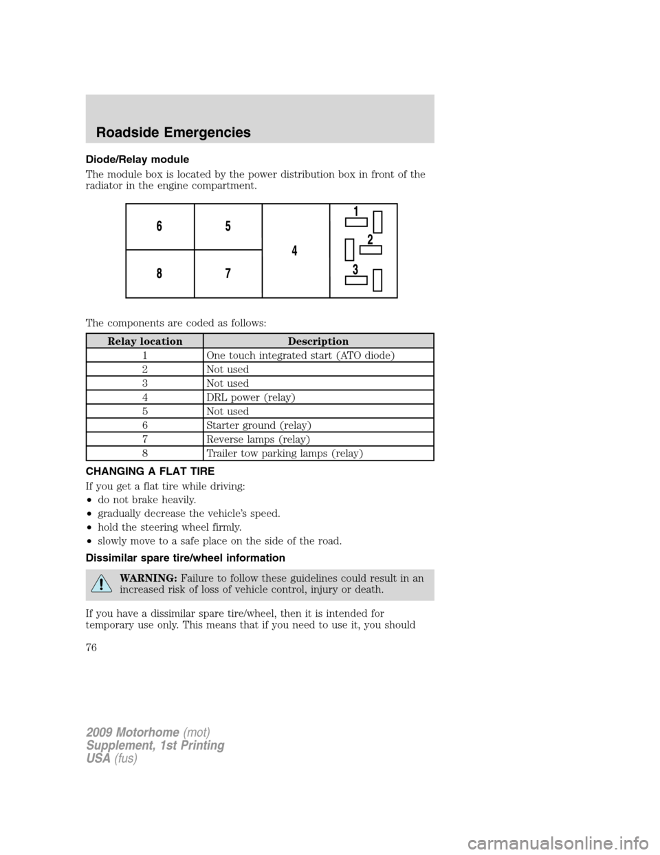
Diode/Relay module
The module box is located by the power distribution box in front of the
radiator in the engine compartment.
The components are coded as follows:
Relay location Description
1 One touch integrated start (ATO diode)
2 Not used
3 Not used
4 DRL power (relay)
5 Not used
6 Starter ground (relay)
7 Reverse lamps (relay)
8 Trailer tow parking lamps (relay)
CHANGING A FLAT TIRE
If you get a flat tire while driving:
•do not brake heavily.
•gradually decrease the vehicle’s speed.
•hold the steering wheel firmly.
•slowly move to a safe place on the side of the road.
Dissimilar spare tire/wheel information
WARNING:Failure to follow these guidelines could result in an
increased risk of loss of vehicle control, injury or death.
If you have a dissimilar spare tire/wheel, then it is intended for
temporary use only. This means that if you need to use it, you should
2009 Motorhome(mot)
Supplement, 1st Printing
USA(fus)
Roadside Emergencies
76
Page 79 of 136
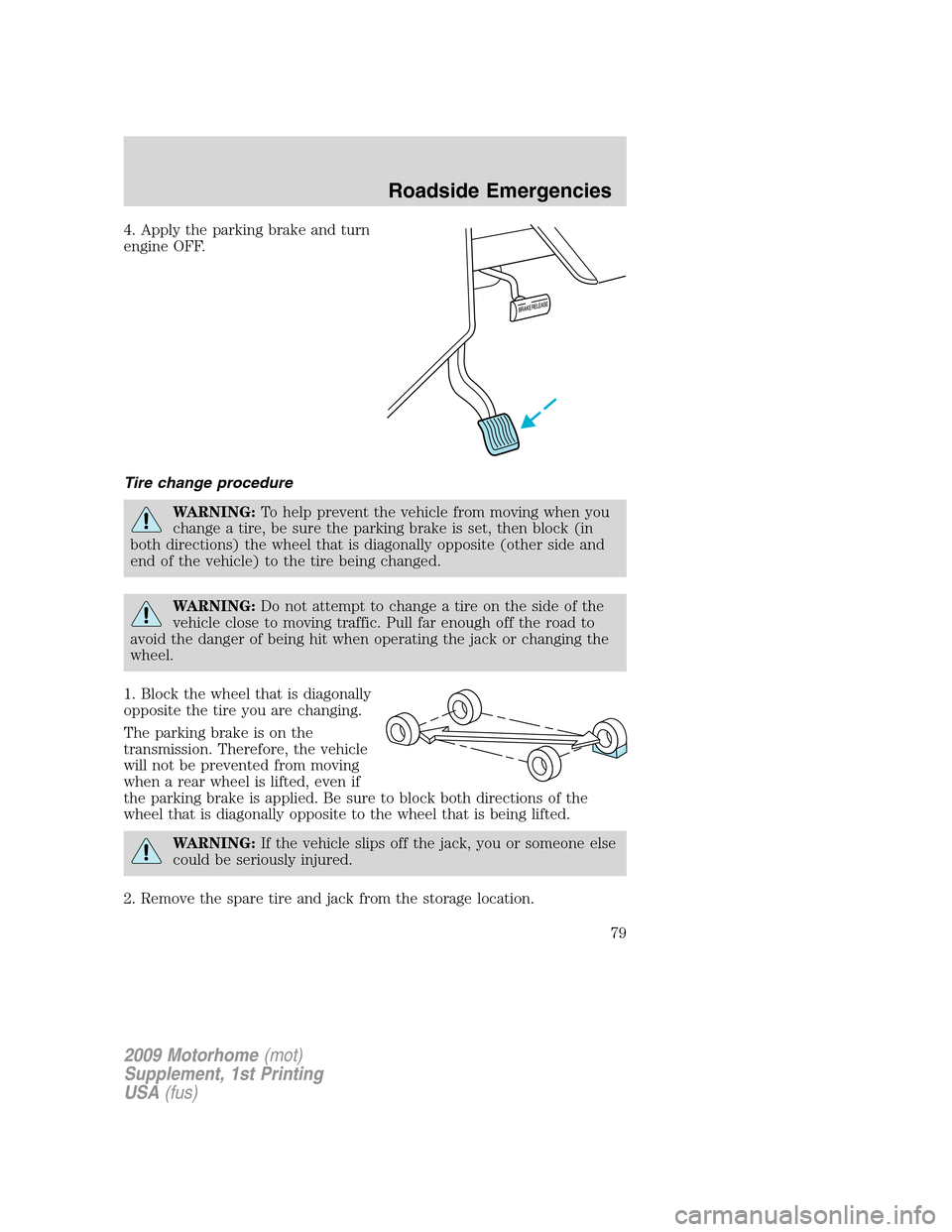
4. Apply the parking brake and turn
engine OFF.
Tire change procedure
WARNING:To help prevent the vehicle from moving when you
change a tire, be sure the parking brake is set, then block (in
both directions) the wheel that is diagonally opposite (other side and
end of the vehicle) to the tire being changed.
WARNING:Do not attempt to change a tire on the side of the
vehicle close to moving traffic. Pull far enough off the road to
avoid the danger of being hit when operating the jack or changing the
wheel.
1. Block the wheel that is diagonally
opposite the tire you are changing.
The parking brake is on the
transmission. Therefore, the vehicle
will not be prevented from moving
when a rear wheel is lifted, even if
the parking brake is applied. Be sure to block both directions of the
wheel that is diagonally opposite to the wheel that is being lifted.
WARNING:If the vehicle slips off the jack, you or someone else
could be seriously injured.
2. Remove the spare tire and jack from the storage location.
2009 Motorhome(mot)
Supplement, 1st Printing
USA(fus)
Roadside Emergencies
79
Page 82 of 136
WHEEL LUG NUT TORQUE SPECIFICATIONS
On vehicles equipped with dual rear wheels, retighten the wheel lug nuts
to the specified torque at 100 miles (160 km), and again at 500 miles
(800 km) of new vehicle operation and after any wheel disturbance (tire
rotation, changing a flat tire, wheel removal, etc.).
Bolt size Wheel lug nut torque*
lb.ft. N•m
19.5 in. wheels: M14 x 1.5 150 200
22.5 in. wheels: M22 x 1.5 450 610
* Torque specifications are for nut and bolt threads free of dirt and
rust. Use only Ford recommended replacement fasteners.
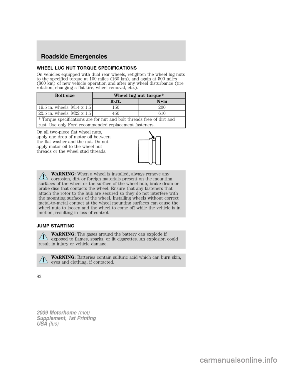
On all two-piece flat wheel nuts,
apply one drop of motor oil between
the flat washer and the nut. Do not
apply motor oil to the wheel nut
threads or the wheel stud threads.
WARNING:When a wheel is installed, always remove any
corrosion, dirt or foreign materials present on the mounting
surfaces of the wheel or the surface of the wheel hub, brake drum or
brake disc that contacts the wheel. Ensure that any fasteners that
attach the rotor to the hub are secured so they do not interfere with
the mounting surfaces of the wheel. Installing wheels without correct
metal-to-metal contact at the wheel mounting surfaces can cause the
wheel nuts to loosen and the wheel to come off while the vehicle is in
motion, resulting in loss of control.
JUMP STARTING
WARNING:The gases around the battery can explode if
exposed to flames, sparks, or lit cigarettes. An explosion could
result in injury or vehicle damage.
WARNING:Batteries contain sulfuric acid which can burn skin,
eyes and clothing, if contacted.
2009 Motorhome(mot)
Supplement, 1st Printing
USA(fus)
Roadside Emergencies
82
Page 83 of 136
Do not attempt to push-start your automatic transmission
vehicle. Automatic transmissions do not have push-start
capability. Attempting to push-start a vehicle with an automatic
transmission may cause transmission damage.
Preparing your vehicle
When the battery is disconnected or a new battery is installed, the
automatic transmission must relearn its shift strategy. As a result, the
transmission may have firm and/or soft shifts. This operation is
considered normal and will not affect function or durability of the
transmission. Over time, the adaptive learning process will fully update
transmission operation.
1.Use only a 12–volt supply to start your vehicle.
2. Do not disconnect the battery of the disabled vehicle as this could
damage the vehicle’s electrical system.
3. Park the booster vehicle close to the hood of the disabled vehicle
making sure the two vehiclesdo nottouch. Set the parking brake on
both vehicles and stay clear of the engine cooling fan and other moving
parts.
4. Check all battery terminals and remove any excessive corrosion before
you attach the battery cables. Ensure that vent caps are tight and level.
5. Turn the heater fan on in both vehicles to protect from any electrical
surges. Turn all other accessories off.
Connecting the jumper cables
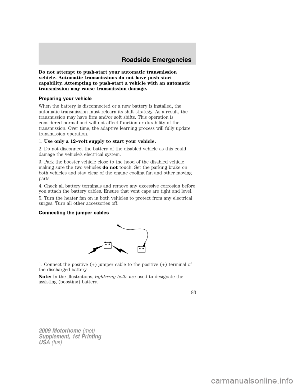
1. Connect the positive (+) jumper cable to the positive (+) terminal of
the discharged battery.
Note:In the illustrations,lightning boltsare used to designate the
assisting (boosting) battery.
+–+–
2009 Motorhome(mot)
Supplement, 1st Printing
USA(fus)
Roadside Emergencies
83
Page 87 of 136
Emergency towing
In case of a roadside emergency with a disabled vehicle (without access
to wheel dollies, car hauling trailer, or flatbed transport vehicle) your
vehicle (regardless of transmission powertrain configuration) can be flat
towed (all wheels on the ground) under the following conditions:
•Vehicle is facing forward so that it is being towed in a forward
direction.
•Place the transmission in N (Neutral). Refer toBrake shift interlock
in theDrivingchapter for specific instructions if you cannot move the
gear shift lever into N (Neutral).
•Maximum speed is not to exceed 35 mph (56 km/h).
•Maximum distance is 50 miles (80 km).
2009 Motorhome(mot)
Supplement, 1st Printing
USA(fus)
Roadside Emergencies
87
Page 95 of 136
CLEANING THE WHEELS
•Clean weekly with Motorcraft Wheel and Tire Cleaner (ZC-37–A),
which is available from your dealer. Heavy dirt and brake dust
accumulation may require agitation with a sponge. Rinse thoroughly
with a strong stream of water.
•Never apply any cleaning chemical to hot or warm wheel rims or
covers.
•Some automatic car washes may cause damage to the finish on your
wheel rims or covers. Chemical-strength cleaners, or cleaning
chemicals, in combination with brush agitation to remove brake dust
and dirt, could wear away the clearcoat finish over time.
•Do not use hydrofluoric acid-based or high caustic-based wheel
cleaners, steel wool, fuels or strong household detergent.
•To remove tar and grease, use Motorcraft Bug and Tar Remover
(ZC-42), available from your dealer.
ENGINE
Engines are more efficient when they are clean because grease and dirt
buildup keep the engine warmer than normal. When washing:
•Take care when using a power washer to clean the engine. The
high-pressure fluid could penetrate the sealed parts and cause
damage.
•Do not spray a hot engine with cold water to avoid cracking the
engine block or other engine components.
•Spray Motorcraft Engine Shampoo and Degreaser (ZC-20) on all parts
that require cleaning and pressure rinse clean. In Canada use
Motorcraft Engine Shampoo (CXC-66-A).
•Never wash or rinse the engine while it is running; water in the
running engine may cause internal damage.
UNDERBODY
Flush the complete underside of your vehicle frequently. Keep body and
door drain holes free from packed dirt.
2009 Motorhome(mot)
Supplement, 1st Printing
USA(fus)
Cleaning
95