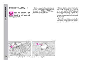
Page 25 of 254

GETTING TO KNOW YOUR CAR
24
Once you have released
the lever, check that the
seat is firmly locked in the
runners by trying to move it back
and forth. Failure to lock the seat
in place could result in the seat
moving suddenly and the driver
losing control of the car.TO ADJUST THE RECLINING
SEAT BACK fig. 24
Pull out the lever Ato its full extent
and move it up or down to get the re-
quired position, then release it.
HEIGHT ADJUSTMENT
(DRIVER’S SEAT) fig. 24
To lift the seat, pull out the lever B
to its full extent and move it up or
down to get the required position. To
lower the seat, pull down the lever B
and move it up or down to get the re-
quired position.IMPORTANTThe adjustment can
only be made sitting in the driving
seat. Do not remove the seats or car-
ry out maintenance and/or repairs on
them: any operations that are not car-
ried out properly may affect the safe-
ty devices; always take your vehicle to
a Fiat Dealership.
LUMBAR ADJUSTMENT
fig. 25
(for versions/markets, where provided)
That provides better support for the
back. Turn knob Ato make the ad-
justment.
FRONT SEATS
MOVING THE SEAT
BACKWARDS
OR FORWARDS fig. 23
Lift lever Aand push the seat back-
wards or forwards.
fig. 23
F0B0015b
fig. 24
F0B0188b
fig. 22
F0B0016b
001-077 ULYSSE ING:001-077 ULYSSE ING 5-11-2009 12:11 Pagina 24
Page 26 of 254

GETTING TO KNOW YOUR CAR
Nero- Magenta 032 PANTONE - Testo
25
ELECTRICALLY
ADJUSTABLE HEATED
FRONT SEATS fig. 26-27
(for versions/markets, where provided)
Adjustments can be made when the
key is at M, and for about 1 minute af-
ter turning the key to S.
A -button for moving the seat back-
wards and forwards;
B -button for adjusting the angle of
the seat back;
C -seat heating on/off switch with
the engine running. The seat heating
can be adjusted according to 4 differ-
ent levels: 0(off), 1(minimum heat-
ing), 2(medium heating), 3(maximum
heating);
D -Controls for the driver’s seat po-
sition storing. STORING PROCEDURE FOR
DRIVER’S SEAT fig. 27
(for versions/markets, where provided)
The system makes it possible to
store 2 different driver's seat positions
connected to buttons 1 and 2.
Proceed as follows to store the ad-
justments available with button 1and
2and the ignition key at M:
– put the seat in the required posi-
tion;
– press button Mand then, within 4
seconds, press button 1to store the
adjustment in “memory 1” or button
2to store the adjustment in “memo-
ry 2”.
A sound signal accompanies suc-
cessful storing.Recalling a stored position
When the engine is off: briefly press
button 1or 2.
IMPORTANTAfter 5 unsuccess-
ful recalls, the system locks the rela-
tive control which will be restored
when the engine is started.
When the engine is on: press and
keep button 1or 2pressed until the
stored position is reached.
fig. 26
F0B0020b
fig. 27
F0B0285b
001-077 ULYSSE ING:001-077 ULYSSE ING 5-11-2009 12:11 Pagina 25
Page 27 of 254

GETTING TO KNOW YOUR CAR
26
FRONT SWIVEL SEATS
fig. 28-29-30
The front seats (driver and passen-
ger) can be turned through 180° to
create a “front parlour” effect.
To do this from outside the vehicle,
proceed as follows:
– put the seat back in vertical posi-
tion;
– take the seat “almost completely
forwards”;– driver’s seat (for versions/markets,
where provided): lift the seat up to the
highest position and adjust the steer-
ing wheel “completely forwards”. The
seats cannot be turned 180° if the
handbrake lever is up. In this case, pull
button Boutwards and lower the
lever. The brakes of the vehicle are still
on in this position;
– lift the release lever Aand, at the
same time, turn the seat 180° inwards
until the “parlour” effect is reached;
the system makes it possible to re-
leased lever Aduring the seat rota-
tion.
Reverse the above mentioned pro-
cedure to put the seat back in driving
position.Before starting off again,
make sure that the seats
are facing the front of the
vehicle and are properly fastened
to their anchorage points. The
seat belts can only be used effec-
tively in this position.
fig. 29 - Electric control versions
F0B0223b
fig. 28 - Mechanic control versions
F0B0290b
fig. 30
F0B0224b
001-077 ULYSSE ING:001-077 ULYSSE ING 5-11-2009 12:11 Pagina 26
Page 28 of 254

GETTING TO KNOW YOUR CAR
27
REAR SEATSWhen the tailgate is open, operate
handle Bof the third row seats as
above mentioned and the luggage
compartment will be widened.TO ADJUST THE RECLINING
SEAT BACK fig. 33
The adjustment can only be made sit-
ting in the seat. Pull out lever Cand
adjust the seat back in the required
position, then release the lever.
“TABLE” POSITION
To use the side seat back as a sup-
porting plane (“table” position), oper-
ate release lever C-fig. 33and guide
the seat to the cushion.
To use the central seat back as a
supporting plane, operate release
lever A-fig. 34and guide the seat to
the cushion.
fig. 31
F0B0203bfig. 32
F0B0025b
fig. 33
F0B0019b
All seat adjustments
must be made when the
vehicle is stationary.
MOVING THE SEAT
BACKWARDS
OR FORWARDS fig. 31-32
To adjust the rear seats (second-
third row), lift lever Aand move the
seat forward or back to get the re-
quired position.
From the third row it is possible to
move the second row seat forward or
back by pulling handle Band moving
the seat at the same time.
fig. 34
F0B0021b
001-077 ULYSSE ING:001-077 ULYSSE ING 5-11-2009 12:11 Pagina 27
Page 29 of 254

GETTING TO KNOW YOUR CAR
28
To put the seat back into vertical po-
sition, push it upwards until it clicks
and locks in that position.
“WALLET” POSITION
Side seats
Operate release lever C-fig. 33and
guide the seat back until the “table”
position is reached; then turn the
tipped seat again until the “wallet” po-
sition illustrated in fig. 36 is reached.
If difficult, use the release lever A –
fig. 34bset rear the seats on the left
side.To restore the seat normal position,
guide it until it engages the runners on
the floor and place the seat back into
vertical position until it clicks and locks
in that position.
USING THIRD ROW SEATS
To get at the rear seats (third row),
lift lever C-fig. 33from the outside
and tip the whole seat forward.
To get out of the car, lift lever D-
fig. 32and tip the seat forward. When the second row
seat is tipped in “wallet”
position, it is not possible
to transport passengers on the
third row seats, as illustrated on
label fig. 36 placed on the seats
themselves. This is a precaution
to avoid any risk of contact with
the articulation mechanisms of
the seat itself.
To restore the seat normal position,
guide it until it engages the runners on
the floor and place the seat back into
vertical position until it clicks and locks
in that position.
Central seat
Operate release lever A-fig. 34and
guide the seat back until the “table”
position is reached;
Lift lever B-fig. 35and guide the
tipped seat until the “wallet” position
is reached.
fig. 35
F0B0292b
fig. 34b
F0B0410b
001-077 ULYSSE ING:001-077 ULYSSE ING 5-11-2009 12:11 Pagina 28
Page 30 of 254

GETTING TO KNOW YOUR CAR
29
DISMANTLING THE SECOND
AND THIRD ROW SEATS
To dismantle:
– operate release lever C-fig. 33and
guide the seat back until the “table”
position is reached; turn the tipped
seat again until the “wallet” position is
reached fig. 36;
– take belt Eand pull it upwards then
remove the whole seat from its hous-
ings on the floor runners.
Reverse the above mentioned pro-
cedure to reassemble the seat.Make sure the anchor-
age holes are always
clean; if debris has got in-
to them it interferes with the
seats being locked securely into
place.THIRD ROW BENCH SEAT
Moving the seat backwards
or forwards fig. 37
Lift lever Aand push the seat back-
wards or forwards.
It is possible to widen the luggage
compartment capacity from the out-
side by pulling handle Band pushing
the bench forwards.
fig. 36
F0B0411b
Before starting off again,
make sure that the seats
are facing the front of the
vehicle and are properly fastened
to their anchorage points. The
seat belts can only be used effec-
tively in this position.
fig. 37
F0B0286b
001-077 ULYSSE ING:001-077 ULYSSE ING 5-11-2009 12:11 Pagina 29
Page 31 of 254

GETTING TO KNOW YOUR CAR
30
– pull handle Dand release the an-
chorages from their housing on the
floor, then fold the bench seat as a
“wallet”.
To restore the bench seat normal
position, guide the tipped seat until it
engages the runners on the floor, then
put the seat back into vertical position
until it clicks and locks in that position.
Dismantling the bench seat
fig. 38
To dismantle:
– fold the bench seat as a “wallet” ac-
cording to the above mentioned pro-
cedure;
– lift lever E while making it closer
to bar F, then grip them both and re-move the bench seat from its housing
on the floor runners.
fig. 38
“Table” position fig. 38
Proceed as follows to tip the bench
seat back in “table” position:
– flatten the head restraints;
– lift lever Cand guide the seat back
to the cushion.
To restore the seat back vertical po-
sition, push it upwards until it clicks
and locks in that position.
“Wallet” position fig. 38
Proceed as follows to tip the bench
seat in “wallet” position:
– flatten the head restraints;
– lift lever Cand guide the seat back
to the cushion;
F0B0022b
Before starting off again,
make sure that the seats
are facing the front of the
vehicle and are properly fastened
to their anchorage points. The
seat belts can only be used effec-
tively in this position.
To disassemble and
thereafter reassemble
the bench seat, it is nec-
essary to keep the backrest firm-
ly folded and flattened onto the
cushion, in order to avoid any risk
of contact with the articulation
mechanisms of the seat itself.
Make sure the anchor-
age holes are always
clean; if debris has got in-
to them it interferes with the
seats being locked securely into
place.
001-077 ULYSSE ING:001-077 ULYSSE ING 5-11-2009 12:11 Pagina 30
Page 32 of 254
GETTING TO KNOW YOUR CAR
31
INTERIOR SETTINGS
Depending on the various outfits that
can be ordered, it is possible to vary
the internal arrangement of the sec-
ond and third row seats as required,
bringing them forwards or moving
them backwards or sideways using the
relative holes in the floor.
If following illustrations show a few
of the basic configurations supplied on
request:
fig. 39- basic five-seat version
fig. 40 - basic five-seat plus 2 seats
version
fig. 41- basic five-seat plus rear seat
bench versionfig. 42- basic six-seat version
fig. 43- arrangement along the left-
hand side
fig. 44- “Game room” arrangement
with central table
fig. 45- “Back parlour” arrangement
fig. 46- Arrangement for “carrying
long objects”.
fig. 39
F0B0026bfig. 40
F0B0027b
fig. 41
F0B0029b
fig. 44
F0B0031b
fig. 42
F0B0028b
fig. 43
F0B0030b
001-077 ULYSSE ING:001-077 ULYSSE ING 5-11-2009 12:11 Pagina 31