2009 FIAT PANDA panel
[x] Cancel search: panelPage 4 of 226

3KNOW YOUR
VEHICLESAFETY
CORRECT USE
OF THE CAR
WARNING LIGHTS
AND MESSAGES
IN
AN EMERGENCY
CAR
MAINTENANCE
TECHNICAL
SPECIFICATIONS
INDEX
KNOW YOUR VEHICLE
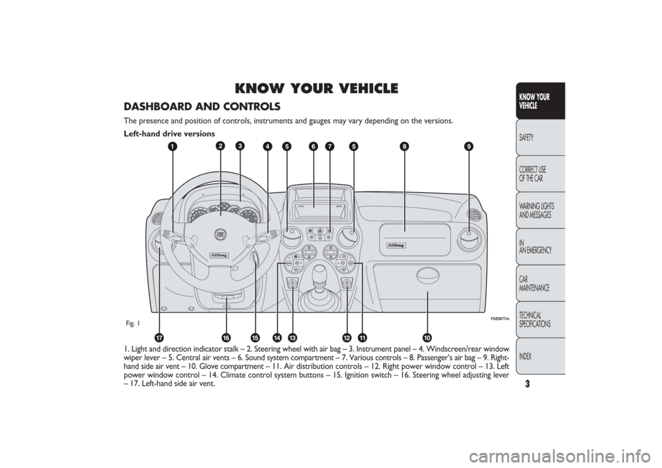
1. Light and direction indicator stalk – 2. Steering wheel with air bag – 3. Instrument panel – 4. Windscreen/rear window
wiper lever – 5. Central air vents – 6. Sound system compartment – 7. Various controls – 8. Passenger’s air bag – 9. Right-
hand side air vent – 10. Glove compartment – 11. Air distribution controls – 12. Right power window control – 13. Left
power window control – 14. Climate control system buttons – 15. Ignition switch – 16. Steering wheel adjusting lever
– 17. Left-hand side air vent.
F0Z0677m
Fig. 1DASHBOARD AND CONTROLSThe presence and position of controls, instruments and gauges may vary depending on the versions.
Left-hand drive versions
001-030 PANDA EN 7-10-2009 13:39 Pagina 3
Page 5 of 226

4
KNOW YOUR
VEHICLE
SAFETY
CORRECT USE
OF THE CAR
WARNING LIGHTS
AND MESSAGES
IN
AN EMERGENCY
CAR
MAINTENANCE
TECHNICAL
SPECIFICATIONS
INDEX
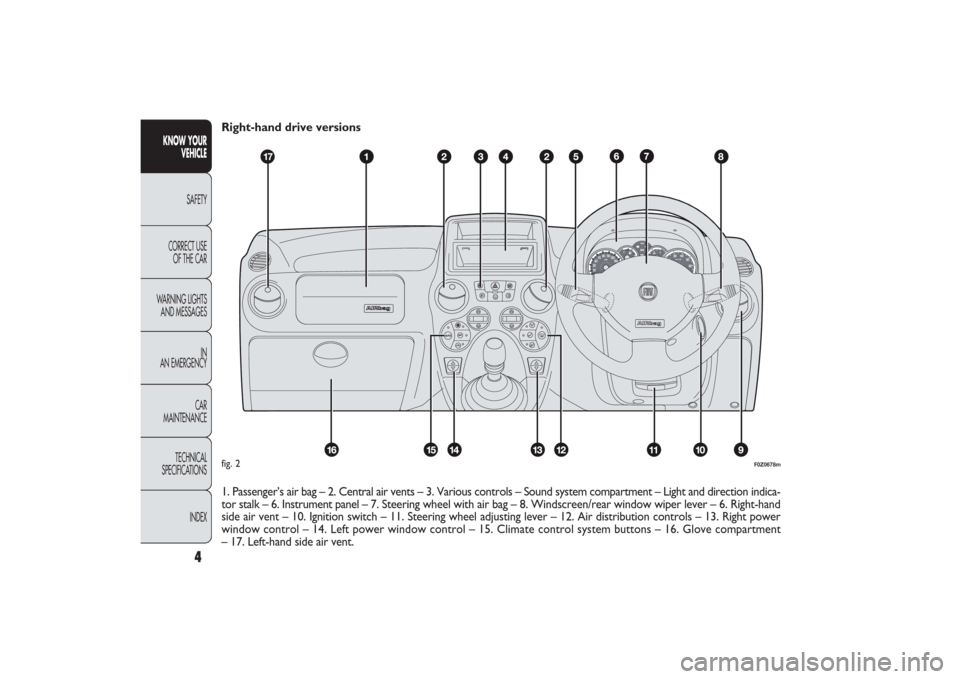
Right-hand drive versions
1. Passenger’s air bag – 2. Central air vents – 3. Various controls – Sound system compartment – Light and direction indica-
tor stalk – 6. Instrument panel – 7. Steering wheel with air bag – 8. Windscreen/rear window wiper lever – 6. Right-hand
side air vent – 10. Ignition switch – 11. Steering wheel adjusting lever – 12. Air distribution controls – 13. Right power
window control – 14. Left power window control – 15. Climate control system buttons – 16. Glove compartment
– 17. Left-hand side air vent.
CH
F
E
F0Z0678m
fig. 2
001-030 PANDA EN 7-10-2009 13:39 Pagina 4
Page 6 of 226

5KNOW YOUR
VEHICLESAFETY
CORRECT USE
OF THE CAR
WARNING LIGHTS
AND MESSAGES
IN
AN EMERGENCY
CAR
MAINTENANCE
TECHNICAL
SPECIFICATIONS
INDEX
F0Z0003m
fig. 3
THE FIAT CODE SYSTEMTo further protect your car from theft, it has been fitted
with an engine immobilising system. It is automatically acti-
vated when the ignition key is removed.
An electronic device, in fact, is fitted in each ignition key grip.
The device transmits a radio-frequency signal when the en-
gine is started through a special aerial built into the igni-
tion switch. The modulated signal, which changes each time
the engine is started, is the “password”, by means of which
the control unit recognises the key and enables to start
the engine.
OPERATION
Each time the car is started by turning the ignition key to
MAR, the Fiat CODE system control unit sends an ac-
knowledgement code to the engine management control
unit to deactivate the inhibitor.
The acknowledgement code is sent only if the Fiat CODE
system control unit has recognised the code transmitted
from the key.
Each time the ignition key is turned to STOP, the Fiat
CODE system deactivates the functions of the engine man-
agement control unit.
If the code has not been recognised correctly, the instru-
ment panel warning light
Y
turns on.
In this case, turn the key to STOP and then back to MAR;
if the lock continues, possibly try with the other keys pro-
vided with the car. If you still cannot start the engine, per-
form the emergency start procedure (see chapter “In an
emergency”) and then contact the Fiat Dealership.
SYMBOLSSpecial coloured labels have been attached near or actu-
ally on some of the components of your car. These labels
bear symbols that remind you of the precautions to be tak-
en as regards that particular component.
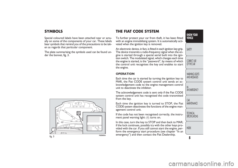
The plate summarising the symbols used can be found un-
der the bonnet, fig. 3.
001-030 PANDA EN 7-10-2009 13:39 Pagina 5
Page 12 of 226

11KNOW YOUR
VEHICLESAFETY
CORRECT USE
OF THE CAR
WARNING LIGHTS
AND MESSAGES
IN
AN EMERGENCY
CAR
MAINTENANCE
TECHNICAL
SPECIFICATIONS
INDEX
INSTRUMENT PANEL
F0Z0250mF0Z0251m
Actual-Active VERSIONS
A Fuel gauge with reserve warning
light
B Speedometer (speed indicator)
C Engine coolant temperature gauge
with excess temperature warning
light
D Digital display.
Warning lights
m
and
c
are only
provided on Diesel versions.
fig. 11 – Left-hand drive versions
fig. 12 – Right-hand drive versions
001-030 PANDA EN 7-10-2009 13:39 Pagina 11
Page 21 of 226

20
KNOW YOUR
VEHICLE
SAFETY
CORRECT USE
OF THE CAR
WARNING LIGHTS
AND MESSAGES
IN
AN EMERGENCY
CAR
MAINTENANCE
TECHNICAL
SPECIFICATIONS
INDEX
Selecting an option from the main menu without submenu:
– briefly press the button MODE to select the main menu
option to be changed;
– press buttons + or − (with a single press) to select the
new setting;
– briefly press the button MODE to store the new set-
ting and at the same time go back to the previously se-
lected main menu option.
Selecting of an option from the main menu with submenu:
– briefly press the button MODE to display the first sub-
menu option;
– press buttons + or − (with a single press) to scroll
through all submenu options;
– briefly press the buttonMODE to select the displayed
submenu option and to open the relevant set-up menu;
– press buttons + or − (with a single press) to choose a
new setting for this submenu option;
– briefly press the button MODE to store the new set-
ting and at the same time go back to the previously se-
lected submenu option. Passenger compartment light adjustment
– to adjust instrument panel, sound system and automat-
ic climate control system display brightness when the stan-
dard screen is active.
Setup menu
– within the menu, they allow you to scroll up and down
through the options;
– during setting operations they increase or decrease
the values.
SETUP MENU fig. 28
The menu comprises a series of functions arranged in a cy-
cle which can be selected through buttons
+and
−to ac-
cess the different select operations and settings (setup)
given in the following paragraphs.
A submenu is provided for some items (Setting the clock
and Set units).
The setup menu is activated by pressing briefly the but-
ton MODE.
Single presses on buttons + or − will scroll the setup menu
options.
Operating modes are different according to the charac-
teristic of the option selected.
001-030 PANDA EN 7-10-2009 13:39 Pagina 20
Page 41 of 226

F0Z0143m
fig. 45
REAR WINDOW DEMISTING/DEFROSTING
fig. 45
Press the button A to activate this function; when this
function is on the instrument panel warning light
(
will
turn on.
This function is timed and it will turn off automatically
after about 20 minutes. Press the button
(
again to switch
the function off.
IMPORTANT Do not apply stickers on the inside of
the rear window over the heating filaments to avoid dam-
age that might cause it to stop working properly. Preventive window demisting procedure
In the event of considerable external moisture and/or rain
and/or large differences in temperature inside and outside
the passenger compartment, perform the following pre-
ventive window demisting procedure:
❒
turn the knob A to the red sector;
❒
make sure the knob C is turned to
U
;
❒
turn the knob D to
-
with the possibility of passing to
position ≤if the windows do not mist up;
❒
turn the knob B to 2
ndspeed.
40
KNOW YOUR
VEHICLE
SAFETY
CORRECT USE
OF THE CAR
WARNING LIGHTS
AND MESSAGES
IN
AN EMERGENCY
CAR
MAINTENANCE
TECHNICAL
SPECIFICATIONS
INDEX
031-064 PANDA EN 7-10-2009 13:43 Pagina 40
Page 49 of 226

F0Z0122m
fig. 48
F0Z0126m
fig. 49
MAIN BEAM HEADLIGHTS fig. 48
With knurled ring in position
2
, push the stalk forward
toward the dashboard (stable position).
The warning light
1
on the instrument panel will come on.
Pulling the stalk towards the steering wheel, the main beams
are turned off and the dipped beams on.
HEADLIGHT FLASHING fig. 48
You can flash the beams pulling the stalk toward the steer-
ing wheel (spring-return position). The warning light
1
on the instrument panel will come on.
PARKING LIGHTS fig. 49
With the ignition key at STOP or removed, turn the
knurled ring to position
6
. The warning light
3
on
the instrument panel will go on with the side/tail lights and
the number plate lights. Move the stalk upwards
a
to turn
on the right side lights only; move it downwards b
to
turn on the left side lights only. In both cases, the warn-
ing light
3
on the instrument panel will not light up.
EXTERNAL LIGHTSThe left-hand stalk operates most of the external lights.
The external lights can only be switched on when the
ignition key is on MAR.
The instrument panel and the different dashboard controls
will come on with the external lights.
LIGHTS SWITCHED OFF fig. 48
Knurled ring turned to position O.
SIDE LIGHTS fig. 48
Turn the knurled ring to position
6
.
The warning light
3
on the instrument panel comes on.
DIPPED BEAM HEADLIGHTS fig. 48
Turn the knurled ring to position
2
.
The warning light
3
on the instrument panel comes on.
48
KNOW YOUR
VEHICLE
SAFETY
CORRECT USE
OF THE CAR
WARNING LIGHTS
AND MESSAGES
IN
AN EMERGENCY
CAR
MAINTENANCE
TECHNICAL
SPECIFICATIONS
INDEX
031-064 PANDA EN 7-10-2009 13:43 Pagina 48
Page 50 of 226

49KNOW YOUR
VEHICLESAFETY
CORRECT USE
OF THE CAR
WARNING LIGHTS
AND MESSAGES
IN
AN EMERGENCY
CAR
MAINTENANCE
TECHNICAL
SPECIFICATIONS
INDEX
the first time and stays lit until the function switches
itself off automatically. Each time the stalk is activated the
time will extend lights switching-on time.
Deactivation
Keep the stalk pulled towards the steering wheel for more
than 2 seconds. DIRECTION INDICATORS fig. 49
Up (position
a) = right-hand direction indicator.
Down (position b) = left-hand direction indicator.
The warning light ¥
or
Î
start flashing on the instrument
panel.
Direction indicators are switched off automatically when
the steering wheel is straightened.
If you want the indicator to flash briefly to show that you
are about to change lane, move the stalk up or down with-
out clicking into position (spring-return position). When
released the stalk will return to its home position.
“FOLLOW ME HOME” DEVICE
This allows the space surrounding the car to be lit up for
a certain period of time.
Activation
With the ignition key on STOP or removed, pull the stalk
towards the steering wheel within 2 minutes from when
the engine is turned off.
At each single movement of the stalk, the lights will re-
main on for an extra 30 seconds up to a maximum of
210 seconds; then the lights are switched off automati-
cally.
Every time the stalk is operated, the warning light
3
,
on the instrument panel switches on. The display will show
the time of activation.
The warning light comes on when the stalk is pulled for
031-064 PANDA EN 7-10-2009 13:43 Pagina 49