2009 FIAT PANDA Button D
[x] Cancel search: Button DPage 4 of 226

3KNOW YOUR
VEHICLESAFETY
CORRECT USE
OF THE CAR
WARNING LIGHTS
AND MESSAGES
IN
AN EMERGENCY
CAR
MAINTENANCE
TECHNICAL
SPECIFICATIONS
INDEX
KNOW YOUR VEHICLE
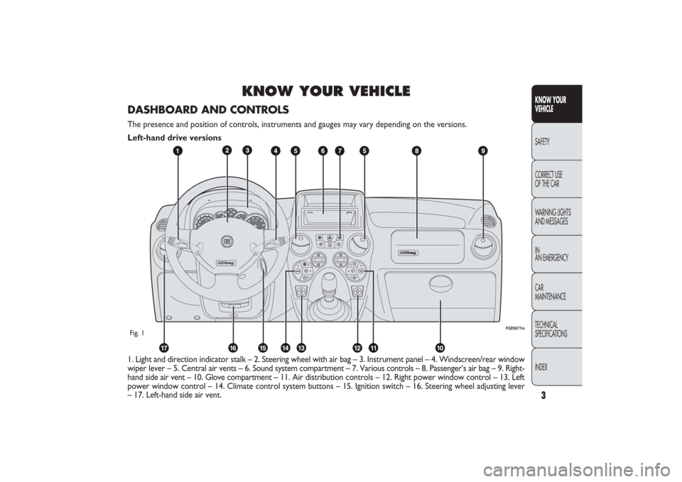
1. Light and direction indicator stalk – 2. Steering wheel with air bag – 3. Instrument panel – 4. Windscreen/rear window
wiper lever – 5. Central air vents – 6. Sound system compartment – 7. Various controls – 8. Passenger’s air bag – 9. Right-
hand side air vent – 10. Glove compartment – 11. Air distribution controls – 12. Right power window control – 13. Left
power window control – 14. Climate control system buttons – 15. Ignition switch – 16. Steering wheel adjusting lever
– 17. Left-hand side air vent.
F0Z0677m
Fig. 1DASHBOARD AND CONTROLSThe presence and position of controls, instruments and gauges may vary depending on the versions.
Left-hand drive versions
001-030 PANDA EN 7-10-2009 13:39 Pagina 3
Page 5 of 226

4
KNOW YOUR
VEHICLE
SAFETY
CORRECT USE
OF THE CAR
WARNING LIGHTS
AND MESSAGES
IN
AN EMERGENCY
CAR
MAINTENANCE
TECHNICAL
SPECIFICATIONS
INDEX
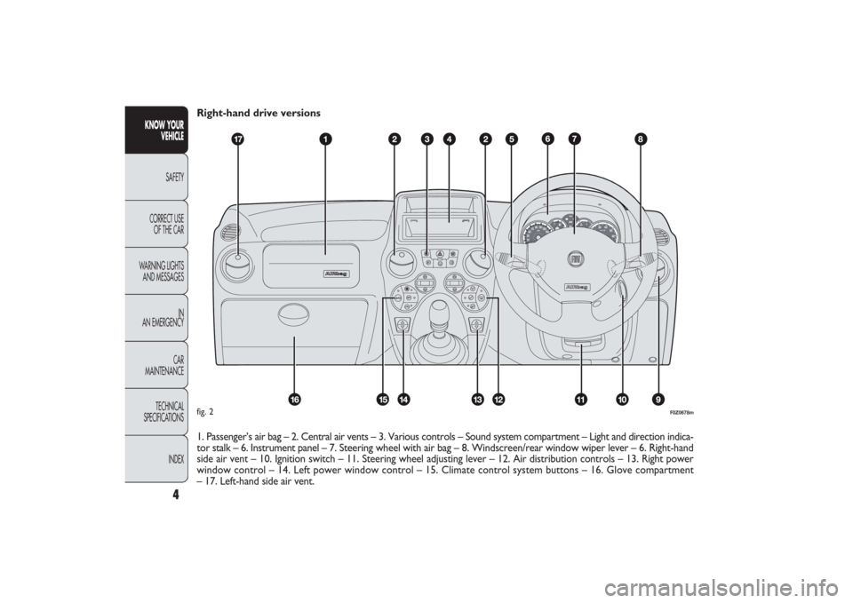
Right-hand drive versions
1. Passenger’s air bag – 2. Central air vents – 3. Various controls – Sound system compartment – Light and direction indica-
tor stalk – 6. Instrument panel – 7. Steering wheel with air bag – 8. Windscreen/rear window wiper lever – 6. Right-hand
side air vent – 10. Ignition switch – 11. Steering wheel adjusting lever – 12. Air distribution controls – 13. Right power
window control – 14. Left power window control – 15. Climate control system buttons – 16. Glove compartment
– 17. Left-hand side air vent.
CH
F
E
F0Z0678m
fig. 2
001-030 PANDA EN 7-10-2009 13:39 Pagina 4
Page 8 of 226

7KNOW YOUR
VEHICLESAFETY
CORRECT USE
OF THE CAR
WARNING LIGHTS
AND MESSAGES
IN
AN EMERGENCY
CAR
MAINTENANCE
TECHNICAL
SPECIFICATIONS
INDEX
F0Z0680m
fig. 5
F0Z0681m
fig. 6
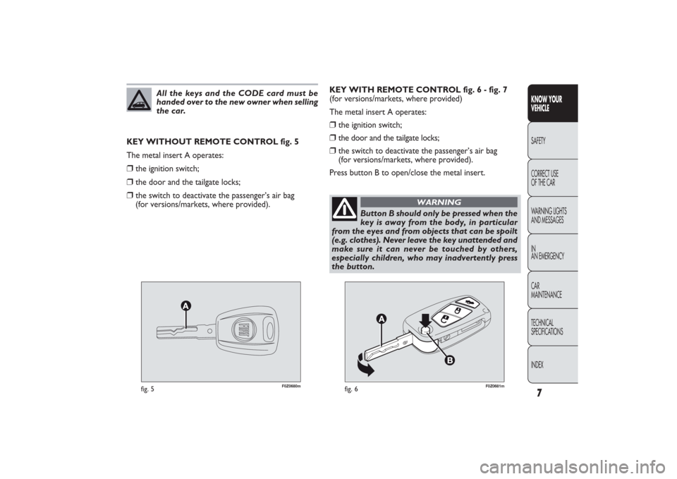
KEY WITH REMOTE CONTROL fig. 6 - fig. 7
(for versions/markets, where provided)
The metal insert A operates:❒
the ignition switch;
❒
the door and the tailgate locks;
❒
the switch to deactivate the passenger’s air bag
(for versions/markets, where provided).
Press button B to open/close the metal insert. KEY WITHOUT REMOTE CONTROL fig. 5
The metal insert A operates:
❒
the ignition switch;
❒
the door and the tailgate locks;
❒
the switch to deactivate the passenger’s air bag
(for versions/markets, where provided).
All the keys and the CODE card must be
handed over to the new owner when selling
the car.
Button B should only be pressed when the
key is away from the body, in particular
from the eyes and from objects that can be spoilt
(e.g. clothes). Never leave the key unattended and
make sure it can never be touched by others,
especially children, who may inadvertently press
the button.
WARNING
001-030 PANDA EN 7-10-2009 13:39 Pagina 7
Page 9 of 226

8
KNOW YOUR
VEHICLE
SAFETY
CORRECT USE
OF THE CAR
WARNING LIGHTS
AND MESSAGES
IN
AN EMERGENCY
CAR
MAINTENANCE
TECHNICAL
SPECIFICATIONS
INDEX
F0Z0682m
fig. 7
When a speed of over 20 km/h is reached, the doors will
be automatically locked if this specific function was set (on-
ly on versions with multifunction reconfigurable display).
Opening the tailgate by the remote control
Press and keep button
R
pressed for over one second
to open (unlock) the tailgate by remote control.
The tailgate opening is indicated by double flashing of
direction indicators.
IMPORTANT If the remote control does not work prop-
erly, it is still possible to carry out the above mentioned
operations by using the metal insert of the key.
REQUEST FOR ADDITIONAL
REMOTE
CONTROLS
The system can recognise up to 8 keys with incorporat-
ed remote control. Should a new key with remote con-
trol be necessary, contact a Fiat Dealership, taking with
you the CODE card, a personal identity document and the
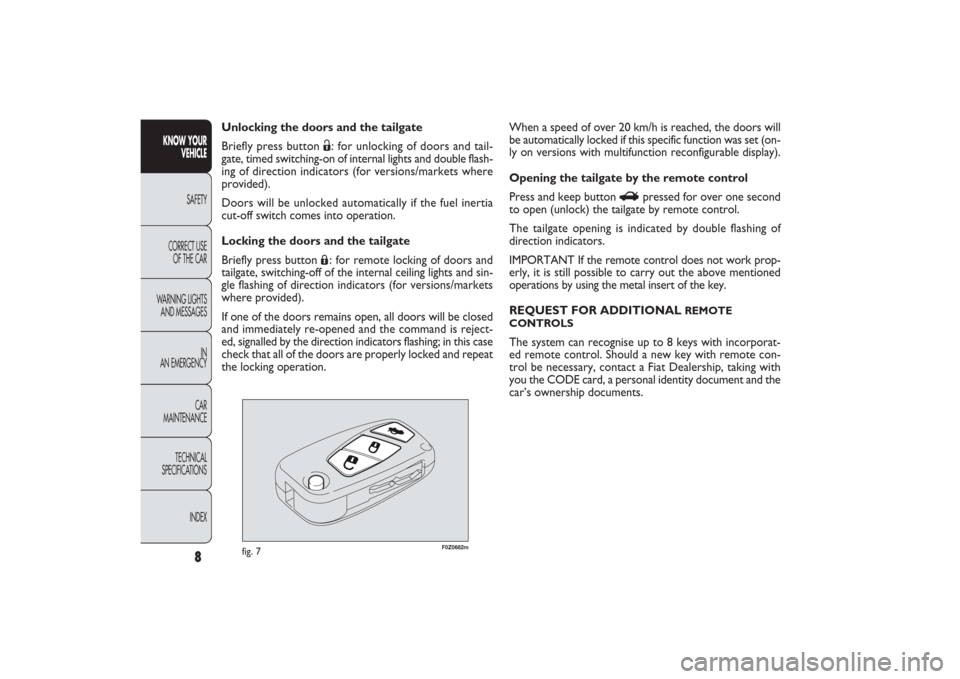
car’s ownership documents. Unlocking the doors and the tailgate
Briefly press button
Ë: for unlocking of doors and tail-
gate, timed switching-on of internal lights and double flash-
ing of direction indicators (for versions/markets where
provided).
Doors will be unlocked automatically if the fuel inertia
cut-off switch comes into operation.
Locking the doors and the tailgate
Briefly press button Á: for remote locking of doors and
tailgate, switching-off of the internal ceiling lights and sin-
gle flashing of direction indicators (for versions/markets
where provided).
If one of the doors remains open, all doors will be closed
and immediately re-opened and the command is reject-
ed, signalled by the direction indicators flashing; in this case
check that all of the doors are properly locked and repeat
the locking operation.
001-030 PANDA EN 7-10-2009 13:39 Pagina 8
Page 17 of 226

16
KNOW YOUR
VEHICLE
SAFETY
CORRECT USE
OF THE CAR
WARNING LIGHTS
AND MESSAGES
IN
AN EMERGENCY
CAR
MAINTENANCE
TECHNICAL
SPECIFICATIONS
INDEX
F0Z0015m
fig. 20
F0Z0027m
fig. 21
CONTROL BUTTONS fig. 21
A Brief pressing to switch from total to trip km/miles.
Long pressing (over 2 seconds) to reset trip km/miles.
B Clock setting.SETTING THE CLOCK fig. 21To set the clock, press the button B. Every pressing on the
button moves the clock forward by one unit. Keeping the
button pressed for some seconds obtains auto-
matic fast increase. When you are close to the required
time, release the button and complete the adjustment
by single presses.
DIGITAL DISPLAY“STANDARD” SCREEN fig. 20
The standard screen shows the following information:
A Headlight aiming position (only with dipped beam
headlights on).
B Clock (always displayed, even with ignition key
removed and front doors closed).
C Odometer (display of covered kilometres or miles).
NOTE With key removed (when opening at least one of
the front doors) the display turns on and shows the
covered kilometres or miles for a few seconds.
001-030 PANDA EN 7-10-2009 13:39 Pagina 16
Page 19 of 226

18
KNOW YOUR
VEHICLE
SAFETY
CORRECT USE
OF THE CAR
WARNING LIGHTS
AND MESSAGES
IN
AN EMERGENCY
CAR
MAINTENANCE
TECHNICAL
SPECIFICATIONS
INDEX
F0I0142m
fig. 24
F0Z0152m
fig. 25
WARNING LIGHT TEST fig. 25
The following warning lights are tested:❒
engaged handbrake/low brake fluid level;
❒
ABS and EBD system (for versions/markets where
provided);
❒
ESP system (for versions/markets where provided);
❒
“Dualdrive” electrical power steering failure.
The diagnosis is automatically run when the key is turned
to MAR and during standard operation when a fault is sig-
nalled. At the end of the initial warning light check, the
message “LEd Error” will flash on the display for about
10 seconds if a faulty warning light is found. SETTING THE CLOCK fig. 24
To adjust the time, press button A to increase minutes, but-
ton B to decrease minutes. Every pressing on the button
moves the clock forward by one unit. Keeping the button
pressed for some seconds obtains automatic fast increase.
When you are close to the required time, release the but-
ton and complete the adjustment by single presses.
001-030 PANDA EN 7-10-2009 13:39 Pagina 18
Page 20 of 226

19KNOW YOUR
VEHICLESAFETY
CORRECT USE
OF THE CAR
WARNING LIGHTS
AND MESSAGES
IN
AN EMERGENCY
CAR
MAINTENANCE
TECHNICAL
SPECIFICATIONS
INDEX
F0Z0017m
fig. 26
F0Z0630m
fig. 27
NOTE When opening one of the front doors, the display
will turn on and show for a few seconds the clock and
the kilometres or miles covered.
CONTROL BUTTONS fig. 27+
To scroll the displayed menu and the related options
upwards or to increase the value displayed.
MODE
Press briefly to enter the menu and/or go to the
next screen or to confirm the required menu
option.
Hold pressed to go back to the standard screen.
–
To scroll the displayed menu and the related options
downwards or to decrease the value displayed.
NOTE Buttons + and − activate different functions ac-
cording to the following situations:
RECONFIGURABLE
MULTIFUNCTION DISPLAY (for versions/markets where provided)The car can be provided with the reconfigurable multifunction
display that shows useful information, according to the previous
settings, when driving.“STANDARD” SCREEN fig. 26
The standard screen shows the following information:
A Date
B Odometer (display of covered km or miles)
C Clock
D External temperature
E Headlight aiming position (only with dipped beam head-
lights on).
001-030 PANDA EN 7-10-2009 13:39 Pagina 19
Page 21 of 226

20
KNOW YOUR
VEHICLE
SAFETY
CORRECT USE
OF THE CAR
WARNING LIGHTS
AND MESSAGES
IN
AN EMERGENCY
CAR
MAINTENANCE
TECHNICAL
SPECIFICATIONS
INDEX
Selecting an option from the main menu without submenu:
– briefly press the button MODE to select the main menu
option to be changed;
– press buttons + or − (with a single press) to select the
new setting;
– briefly press the button MODE to store the new set-
ting and at the same time go back to the previously se-
lected main menu option.
Selecting of an option from the main menu with submenu:
– briefly press the button MODE to display the first sub-
menu option;
– press buttons + or − (with a single press) to scroll
through all submenu options;
– briefly press the buttonMODE to select the displayed
submenu option and to open the relevant set-up menu;
– press buttons + or − (with a single press) to choose a
new setting for this submenu option;
– briefly press the button MODE to store the new set-
ting and at the same time go back to the previously se-
lected submenu option. Passenger compartment light adjustment
– to adjust instrument panel, sound system and automat-
ic climate control system display brightness when the stan-
dard screen is active.
Setup menu
– within the menu, they allow you to scroll up and down
through the options;
– during setting operations they increase or decrease
the values.
SETUP MENU fig. 28
The menu comprises a series of functions arranged in a cy-
cle which can be selected through buttons
+and
−to ac-
cess the different select operations and settings (setup)
given in the following paragraphs.
A submenu is provided for some items (Setting the clock
and Set units).
The setup menu is activated by pressing briefly the but-
ton MODE.
Single presses on buttons + or − will scroll the setup menu
options.
Operating modes are different according to the charac-
teristic of the option selected.
001-030 PANDA EN 7-10-2009 13:39 Pagina 20