Page 272 of 449
WARNING!
Both Anti-Lock Brake Systems contain sophisticated
electronic equipment. It may be susceptible to inter-
ference caused by improperly installed or high out-
put radio transmitting equipment. This interference
can cause possible loss of anti-lock braking capabil-
ity. Installation of such equipment should be done by
qualified professionals.
Four-Wheel Anti-Lock Brake System (ABS)
4-Wheel ABS is designed to aid the driver in maintaining
vehicle control under adverse braking conditions. The
system operates with a separate computer to modulate
hydraulic pressure, to prevent wheel lock-up and help
avoid skidding on slippery surfaces.The system's pump motor runs during an ABS stop to
provide regulated hydraulic pressure. The pump motor
makes a low humming noise during operation, which is
normal.
The ABS includes an amber ABS warning light. When the
light is illuminated, the ABS is not functioning. The
system reverts to standard non-anti-lock brakes. Turning
the ignition OFF and ON again may reset the ABS if the
fault detected was only momentary.WARNING!
Pumping of the Anti-Lock Brakes will diminish their
effectiveness and may lead to an accident. Pumping
makes the stopping distance longer. Just press firmly
on your brake pedal when you need to slow down or
stop.
270 STARTING AND OPERATING
Page 289 of 449
WARNING!
Tires and the spare tire should be replaced after six
years, regardless of the remaining tread. Failure to
follow this warning can result in sudden tire failure.
You could lose control and have an accident resulting
in serious injury or death.
Keep dismounted tires in a cool, dry place with as little
exposure to light as possible. Protect tires from contact
with oil, grease, and gasoline.
Replacement Tires
The tires on your new vehicle provide a balance of many
characteristics. They should be inspected regularly forwear and correct cold tire inflation pressure. The manu-
facturer strongly recommends that you use tires equiva-
lent to the originals in size, quality and performance
when replacement is needed. (Refer to the paragraph on
ªTread Wear Indicatorsº). Refer to the ªTire and Loading
Informationº placard for the size designation of your tire.
The service description and load identification will be
found on the original equipment tire. Failure to use
equivalent replacement tires may adversely affect the
safety, handling, and ride of your vehicle. We recommend
that you contact your original equipment or an autho-
rized tire dealer with any questions you may have on tire
specifications or capability.
STARTING AND OPERATING 287
5
Page 298 of 449

fault condition no longer exists. A system fault can occur
by any of the following scenarios: 1) Jamming due to
electronic devices or driving next to facilities emitting the
same radio frequencies as the TPM sensors; 2) Installing
some form of aftermarket window tinting that affects
radio wave signals; 3) Lots of snow or ice around the
wheels or wheel housings; 4) Using tire chains on the
vehicle; 5) Using wheels/tires not equipped with TPM
sensors.
NOTE: Your vehicle is equipped with a non-matching
full size spare wheel and tire assembly.
1. This spare tire does not have a tire pressure monitor-
ing sensor. Therefore, the TPMS will not monitor the tire
pressure in the spare tire.
2. If you install the full size spare tire in place of a road
tire that has a pressure below the low-pressure warninglimit, upon the next ignition key cycle a chime will sound
and the TPM Telltale Lamp will still turn ON due to the
low tire.
3. However, after driving the vehicle for up to 10 min-
utes above 15 mph (25 km/h), the TPM Telltale Lamp
will flash on and off for 75 seconds and then remain on
solid.
4. For each subsequent ignition key cycle, a chime will
sound and the TPM Telltale Light will flash on and off for
75 seconds and then remain on solid.
5. Once you repair or replace the original road tire, and
reinstall it on the vehicle in place of the full size spare tire,
the TPMS will update automatically and the TPM Telltale
Lamp will turn OFF, as long as no tire pressure is below
the low-pressure warning limit in any of the four active
road tires. The vehicle may need to be driven for up to
10 minutes above 15 mph (25 km/h) in order for the
TPMS to receive this information.
296 STARTING AND OPERATING
Page 322 of 449
CAUTION!
If the trailer weighs more than 1,000 lbs (454 kg)
loaded, it should have its own brakes and they
should be of adequate capacity. Failure to do this
could lead to accelerated brake lining wear, higher
brake pedal effort, and longer stopping distances.
WARNING!
Do not connect trailer brakes to your vehicle's hy-
draulic brake lines. It can overload your brake sys-
tem and cause it to fail. You might not have brakes
when you need them and could have an accident.
Towing any trailer will increase your stopping dis-
tance. When towing you should allow for additional
space between your vehicle and the vehicle in front
of you. Failure to do so could result in an accident.
Towing Requirements Ð Trailer Lights and Wiring
Whenever you pull a trailer, regardless of the trailer size,
stop lights and turn signals on the trailer are required for
motoring safety.
The Trailer Tow Package may include a 4 and 7-pin
wiring harness. Use a factory approved trailer harness
and connector.
NOTE:Do not cut or splice wiring into the vehicle's
wiring harness.
The electrical connections are all complete to the vehicle
but you must mate the harness to a trailer connector.
Refer to the following illustrations:
320 STARTING AND OPERATING
Page 325 of 449

þWhen using the speed control, if you experience speed
drops greater than 10 mph (16 km/h), disengage until
you can resume cruising speed.
þUse speed control in flat terrain and with light loads to
maximize fuel efficiency.
Towing Tips Ð Cooling System
To reduce potential for engine and transmission over-
heating, take the following actions:
þCity Driving
When stopped for short periods of time, put transmission
in NEUTRAL and increase engine idle speed.
þHighway Driving
Reduce speed.
þAir Conditioning
Turn off temporarily.
SNOWPLOW
Snow plows, winches, and other aftermarket equipment
shouldnotbe added to the front end of your vehicle. The
airbag crash sensors may be affected by the change in the
front end structure. The airbags could deploy unexpect-
edly or could fail to deploy during a collision.
WARNING!
Do not add a snow plow, winches, or any other
aftermarket equipment to the front of your vehicle.
This could adversely affect the functioning of the
airbag system and you could be injured.
STARTING AND OPERATING 323
5
Page 330 of 449

NOTE:
²Steps 1 through 5 are requirements that must be met
prior to depressing the NEUTRAL selection button,
and must continue to be met until 1 second elapses
and the shift has been completed. If any of these
requirements (with the exception of 3 - key ON) are
not met prior to depressing the NEUTRAL button or
are no longer met during the 1 second time, then all of
the mode position indicator lights will flash continu-
ously until all requirements are met or until the
NEUTRAL button is released.
²The ignition key must be ON for a shift to take place
and for the position indicator lights to be operable. If
the key is not ON, the shift will not take place and no
position indicator lights will be on or flashing.
²Flashing NEUTRAL position indicator light indicates
that shift requirements have not been met.
WARNING!
You or others could be injured if you leave the
vehicle unattended with the transfer case in the
NEUTRAL position without first fully engaging the
parking brake. The transfer case NEUTRAL position
disengages both the front and rear driveshafts from
the powertrain and will allow the vehicle to move
despite the transmission position. The parking brake
should always be applied when the driver is not in
the vehicle.
328 STARTING AND OPERATING
Page 343 of 449
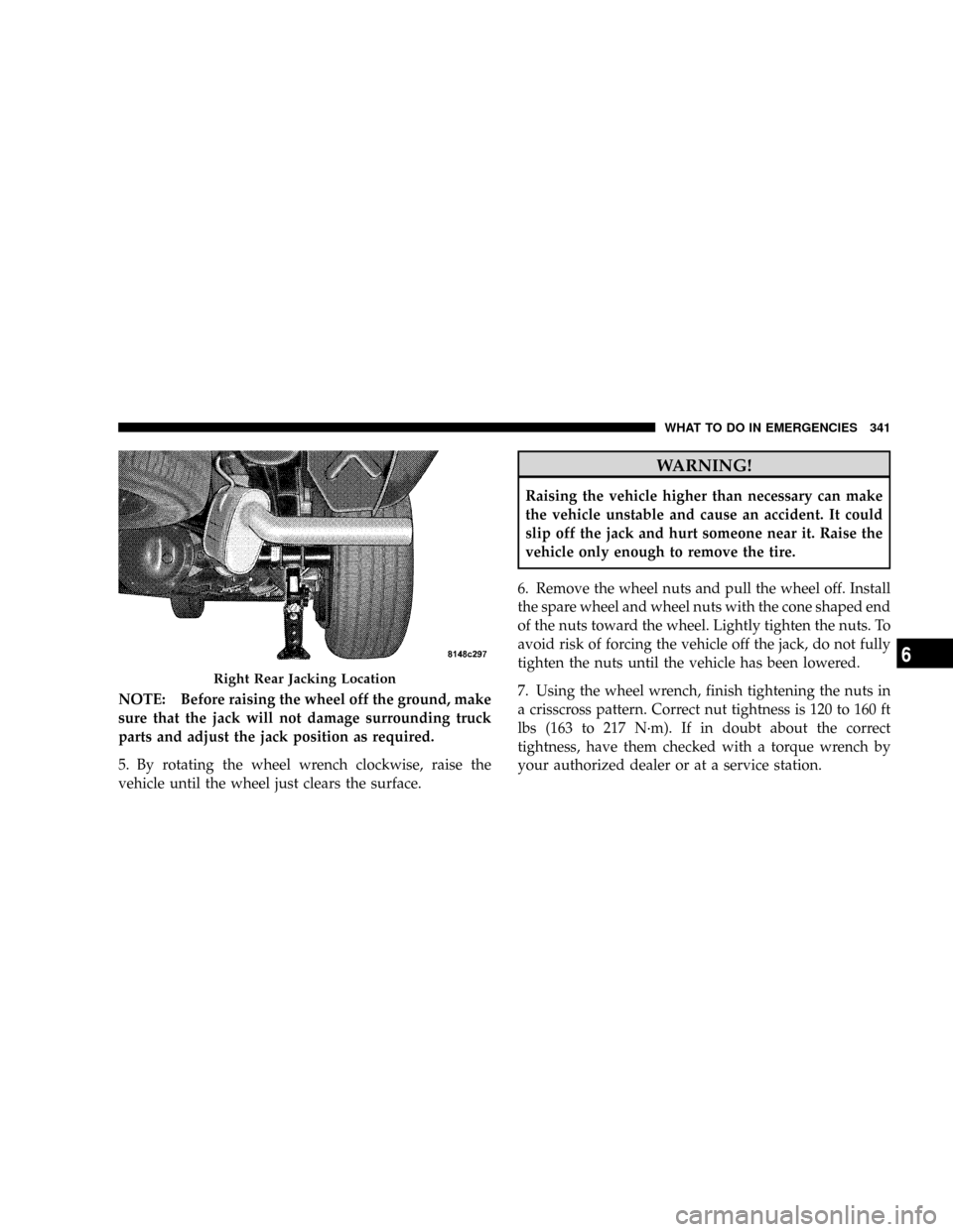
NOTE: Before raising the wheel off the ground, make
sure that the jack will not damage surrounding truck
parts and adjust the jack position as required.
5. By rotating the wheel wrench clockwise, raise the
vehicle until the wheel just clears the surface.
WARNING!
Raising the vehicle higher than necessary can make
the vehicle unstable and cause an accident. It could
slip off the jack and hurt someone near it. Raise the
vehicle only enough to remove the tire.
6. Remove the wheel nuts and pull the wheel off. Install
the spare wheel and wheel nuts with the cone shaped end
of the nuts toward the wheel. Lightly tighten the nuts. To
avoid risk of forcing the vehicle off the jack, do not fully
tighten the nuts until the vehicle has been lowered.
7. Using the wheel wrench, finish tightening the nuts in
a crisscross pattern. Correct nut tightness is 120 to 160 ft
lbs (163 to 217 N´m). If in doubt about the correct
tightness, have them checked with a torque wrench by
your authorized dealer or at a service station.
Right Rear Jacking Location
WHAT TO DO IN EMERGENCIES 341
6
Page 345 of 449
To Stow the Flat or Spare
Turn the wheel so that the valve stem is down. Slide the
wheel retainer through the center of the wheel and
position it properly across the wheel opening.
For convenience in checking the spare tire inflation, stow
with the valve stem toward the rear of the vehicle.
Rotate the winch mechanism until the wheel is drawn
into place against the underside of the vehicle. Continue
to rotate until you feel the winch mechanism slip or click
three times. It cannot be overtightened. Push against the
tire several times to be sure it is firmly in place.
NOTE:To Stow the Flat or Spare: Wheel retainer does
not fit through the center of the aluminum wheel. The tire
must be stored in a safe manner in the bed of the truck.
JUMP±STARTING
WARNING!
²Battery fluid is a corrosive acid solution; do not
allow battery fluid to contact eyes, skin or cloth-
ing. Don't lean over battery when attaching
clamps or allow the clamps to touch each other. If
acid splashes in eyes or on skin, flush the contami-
nated area immediately with large quantities of
water.
²A battery generates hydrogen gas which is flam-
mable and explosive. Keep flame or spark away
from the vent holes. Do not use a booster battery
or any other booster source with an output that
exceeds 12-Volts.
Check the Battery Test Indicator (if equipped). If a light or
bright colored dot is visible in the indicator, DO NOT
jump-start the battery.
WHAT TO DO IN EMERGENCIES 343
6