Page 147 of 484
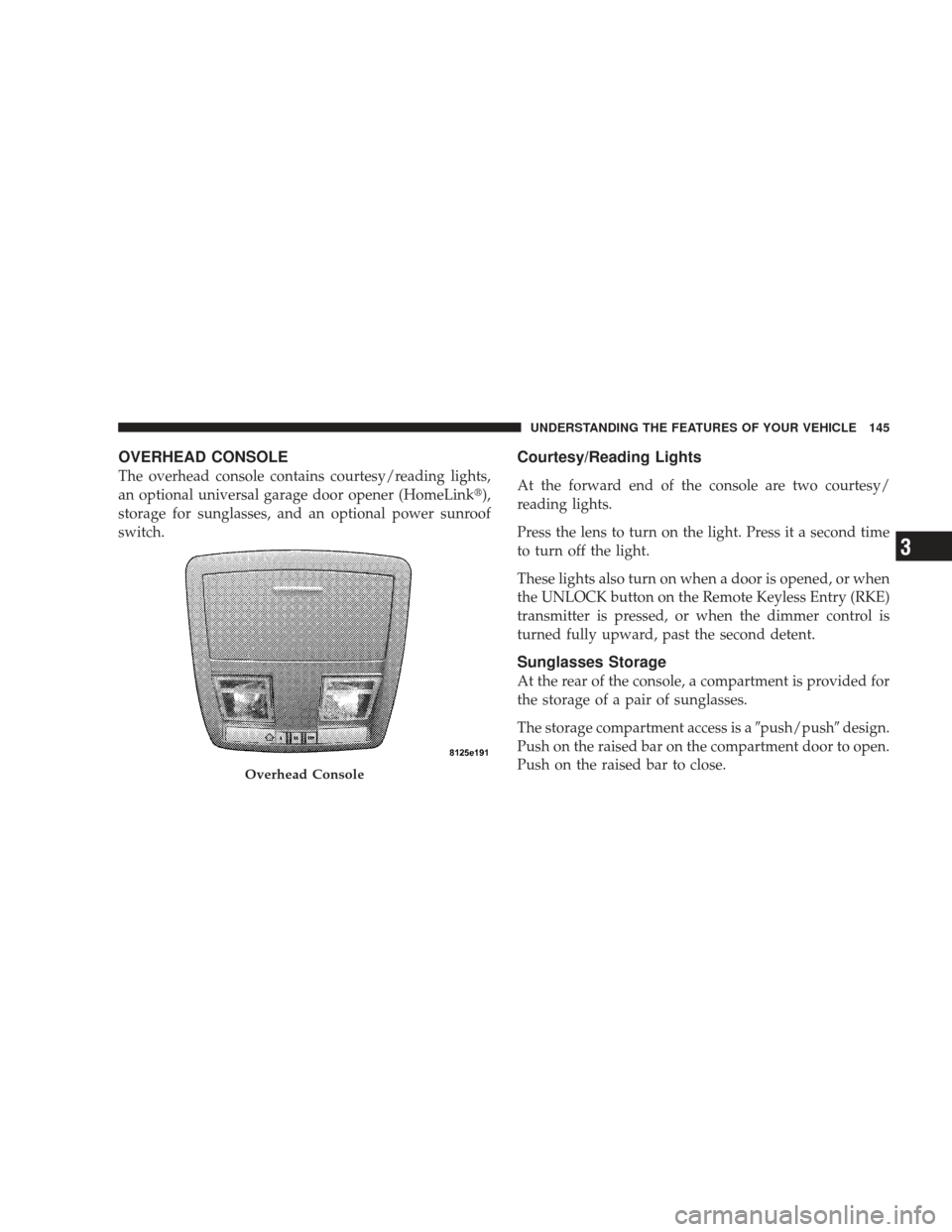
OVERHEAD CONSOLE
The overhead console contains courtesy/reading lights,
an optional universal garage door opener (HomeLink�),
storage for sunglasses, and an optional power sunroof
switch.
Courtesy/Reading Lights
At the forward end of the console are two courtesy/
reading lights.
Press the lens to turn on the light. Press it a second time
to turn off the light.
These lights also turn on when a door is opened, or when
the UNLOCK button on the Remote Keyless Entry (RKE)
transmitter is pressed, or when the dimmer control is
turned fully upward, past the second detent.
Sunglasses Storage
At the rear of the console, a compartment is provided for
the storage of a pair of sunglasses.
The storage compartment access is a�push/push�design.
Push on the raised bar on the compartment door to open.
Push on the raised bar to close.
Overhead Console
UNDERSTANDING THE FEATURES OF YOUR VEHICLE 145
3
Page 148 of 484
GARAGE DOOR OPENER — IF EQUIPPED
HomeLink�replaces up to three remote controls (hand-
held transmitters) that operate devices such as garage
door openers, motorized gates, lighting, or home security
systems. The HomeLink� unit operates off your vehicle’s
battery.
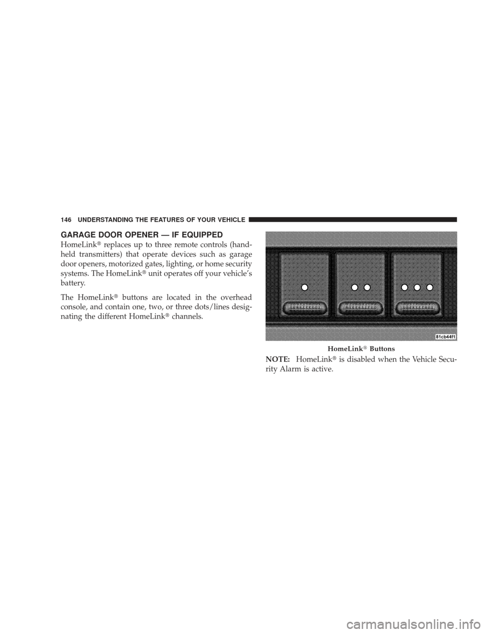
The HomeLink� buttons are located in the overhead
console, and contain one, two, or three dots/lines desig-
nating the different HomeLink� channels.
NOTE:HomeLink� is disabled when the Vehicle Secu-
rity Alarm is active.
HomeLink� Buttons
146 UNDERSTANDING THE FEATURES OF YOUR VEHICLE
Page 152 of 484
 after several seconds of
transmission – which may not be long enough for
Ho")
Gate Operator/Canadian Programming
Canadian radio-frequency laws require transmitter sig-
nals to “time-out” (or quit) after several seconds of
transmission – which may not be long enough for
HomeLink�to pick up the signal during programming.
Similar to this Canadian law, some U.S. gate operators are
designed to “time-out” in the same manner.
It may be helpful to unplug the device during the cycling
process to prevent possible overheating of the garage
door or gate motor.
If you are having difficulties programming a garage door
opener or a gate operator, replace “Programming
HomeLink” Step 3 with the following:
3. Continue to press and hold the HomeLink� button
while you press and release - every two seconds
(“cycle”) your hand-held transmitter until HomeLink �has successfully accepted the frequency signal. The
EVIC display will change from “CHANNEL # TRAIN-
ING” to “CHANNEL # TRAINED.”
If you unplugged the device for training, plug it back in
at this time.
Then proceed with Step 4 under “Programming
HomeLink�” earlier in this section.
Using HomeLink�
To operate, simply press and release the programmed
HomeLink�
button. Activation will now occur for the
trained device (i.e., garage door opener, gate operator,
security system, entry door lock, home/office lighting,
etc.) The hand-held transmitter of the device may also be
used at any time.
150 UNDERSTANDING THE FEATURES OF YOUR VEHICLE
Page 157 of 484
, th")
Sunroof Maintenance
Use only a nonabrasive cleaner and a soft cloth to clean
the glass panel.
Ignition Off Operation
For vehicles not equipped with the Electronic Vehicle
Information Center (EVIC), the power sunroof switch
will remain active for 10 minutes after the ignition switch
is turned OFF. Opening either front door will cancel this
feature.
For vehicles equipped with the EVIC, the power sunroof
switch will remain active for up to 60 minutes after the
ignition switch is turned OFF. Opening either front door
will cancel this feature. The time is programmable. Refer
to “Delay Power Off to Accessories Until Exit,” under
“Personal Settings (Customer-Programmable Features)”
under “Electronic Vehicle Information Center (EVIC)” in
Section 4.
Sunroof Fully Closed
Press the switch forward and release to ensure that the
sunroof is fully closed.
ELECTRICAL POWER OUTLETS
There are two 12-Volt electrical outlets on this vehicle.
Both of the outlets are protected by a fuse.
The 12-Volt power outlet next to the ash receiver tray (if
equipped with an optional Smoker’s Package) has power
available only when the ignition is ON. This outlet will
also operate a conventional cigar lighter unit.
WARNING!
Do not place ashes inside the cubby bin located on
the center console on vehicles not equipped with the
ash receiver tray. A fire leading to bodily injury could
result.
UNDERSTANDING THE FEATURES OF YOUR VEHICLE 155
3
Page 159 of 484

WARNING!
To avoid serious injury or death:
•Do not use a three-prong adapter.
•Do not insert any objects into the receptacles.
•Do not touch with wet hands.
•Close the lid when not in use and while driving
the vehicle.
•If this outlet is mishandled, it may cause an
electric shock and failure.
CAUTION!
•Many accessories that can be plugged in draw
power from the vehicle’s battery even when not in
use (i.e., cellular phones, etc.). Eventually, if
plugged in long enough, the vehicle’s battery will
discharge sufficiently to degrade battery life
and/or prevent engine starting.
•Accessories that draw higher power (i.e., coolers,
vacuum cleaners, lights, etc.) will degrade the
battery even more quickly. Only use these inter-
mittently and with greater caution.
•After the use of high power draw accessories or
long periods of the vehicle not being started (with
accessories still plugged in), the vehicle must be
driven a sufficient length of time to allow the
alternator to recharge the vehicle’s battery.(Continued)
UNDERSTANDING THE FEATURES OF YOUR VEHICLE 157
3
Page 171 of 484
INSTRUMENT PANEL FEATURES
1 — Air Outlet7 — Climate Control13 — Hood Release
2 — Instrument Cluster 8 — Heated Seat Switch*14 — Trunk Release Switch
3 — Hazard Switch 9 — Power Outlet15 — Headlight Switch
4 — Electronic Stability Program OFF Button* /
Traction Control System OFF Button* 10 — Ash Tray*
* If Equipped
5 — Glove Compartment 11 — Storage Compartment*
6 — Radio 12 — Ignition SwitchUNDERSTANDING YOUR INSTRUMENT PANEL 169
4
Page 174 of 484

INSTRUMENT CLUSTER DESCRIPTIONS
1. Fuel Gauge
The pointer shows the level of fuel in the fuel tank when
the ignition switch is in the ON position.
2. Trip Odometer Button
Base Cluster
The word�TRIP�will appear when this button is pressed.
Push in and hold the button for two seconds when the
trip odometer displays to reset it to 0 miles (km). A
second press of the button will display the outside
temperature in the odometer.
Premium Cluster
Press this button to change the display from odometer to
either of two trip odometer settings. The letter “A” or “B”
will appear when in the trip odometer mode. Push in and hold the button for two seconds to reset the trip odometer
to 0 miles (km). The odometer must be in TRIP mode to
reset it.
3. Speedometer
Indicates vehicle speed.
4. Electronic Speed Control Indicator Light — If
Equipped
This light will turn on when the electronic
speed control is ON.
5. Tachometer
The red segments indicate the maximum permissible
engine revolutions per minute (RPM x 1000) for each gear
range. Ease up on the accelerator before reaching the red
area.
172 UNDERSTANDING YOUR INSTRUMENT PANEL
Page 175 of 484

6. Charging System LightThis light shows the status of the electrical charg-
ing system. The light should come on when the
ignition switch is first turned ON and remain on briefly
as a bulb check. If the light stays on or comes on while
driving, turn off some of the vehicle’s non-essential
electrical devices or increase engine speed (if at idle). If
the charging system light remains on, it means that the
vehicle is experiencing a problem with the charging
system. Obtain SERVICE IMMEDIATELY. See an autho-
rized dealer.
7. Electronic Throttle Control (ETC) Light This light will turn on briefly as a bulb check
when the ignition switch is turned ON. This
light will also turn on while the engine is
running if there is a problem with the Elec-
tronic Throttle Control (ETC) system. If the light comes on while the engine is running, safely
bring the vehicle to a complete stop as soon as possible,
place the shift lever in PARK, and cycle the ignition key.
The light should turn off. If the light remains lit with the
engine running, your vehicle will usually be drivable.
However, see an authorized dealer for service as soon as
possible.
If the light is flashing when the engine is running,
immediate service is required. In this case, you may
experience reduced performance, an elevated/rough idle
or engine stall, and your vehicle may require towing.
Also, have the system checked by an authorized dealer if
the light does not come on during starting.
8. Temperature Gauge
The temperature gauge shows engine coolant tempera-
ture. Any reading within the normal range indicates that
the engine cooling system is operating satisfactorily.
UNDERSTANDING YOUR INSTRUMENT PANEL 173
4