Page 242 of 484
•During all List modes, the iPod�displays all lists in
“wrap-around” mode. So if the track is at the
bottom of the list just turn the wheel backwards
(counter-clockwise) to get to the track faster.
•In List mode, the radio PRESETButtons are used as
shortcuts to the following lists on the iPod�.
•Preset 1 – Playlists
•Preset 2 – Artists
•Preset 3 – Albums
•Preset 4 – Genres
•Preset 5 - Audiobooks
•Preset 6 – Podcasts
•Pressing a PRESET button, will display the current
list on the top line and the first item in that list on
the second line.
•To Exit List mode without selecting a track, press the
same PRESET button again to go back to Play
mode.
•LIST button: The LISTbutton will display the top
level menu of the iPod�. Turn the TUNEcontrol knob
to list the top-menu item you wish to select and press
the TUNE control knob. This will display the next
sub-menu list item on the iPod� then you can follow
the same steps to go to the desired track in that list.
Not all iPod� sub-menu levels are available on this
system.
•MUSIC TYPE button: TheMUSIC TYPE button is
another shortcut button to the genre listing on your
iPod�.
240 UNDERSTANDING YOUR INSTRUMENT PANEL
Page 246 of 484
SCAN Button (When Equipped)
Pressing the SCAN button causes the tuner to search for
the next channel, pausing for eight seconds before con-
tinuing to the next. To stop the search, press the SCAN
button a second time.
INFO Button — Except REU Radio
Pressing the INFO button will cycle the display informa-
tion between Artist, Song Title, and Composer (if avail-
able). Also, pressing and holding the INFO button for an
additional three seconds will make the radio display the
song title all of the time (press and hold again to return to
normal display).
INFO Button — REU Radio
Pressing the INFO button will display information about
Artist, Song Title, and Composer (if available). Pressing
the INFO button again will close the INFO screen.
RW/FF
Pressing the RW (Rewind) or FF (Fast Forward) buttons
causes the tuner to search for the next channel in the
direction of the arrows.
TUNE Control (Rotary)
Turn the rotary TUNE/SCROLL control knob clockwise
to increase or counterclockwise to decrease the channel.
MUSIC TYPE Button — Except REU Radio
Pressing this button once will turn on the Music Type
mode for five seconds. Pressing the MUSIC TYPE button
or turning the TUNE/SCROLL control knob within five
seconds will allow the program format type to be se-
lected.
Toggle the MUSIC TYPE button again to select the music
type.
244 UNDERSTANDING YOUR INSTRUMENT PANEL
Page 252 of 484
•Two wireless infrared headsets allow rear seat passen-
gers to listen to the same or individual audio sources.Audio/Video RCA Jacks (AUX Jacks)
on the rear of the center console enable
the monitor to display video directly
from a video camera, connect video
games for display on the screen, or
play music directly from an MP3
player.
1. Video in (yellow)
2. Left audio in (white)
3. Right audio in (red)
NOTE: Refer to your “Vehicle Entertainment System
(VES)™ Users Manual” for detailed operating instruc-
tions.REMOTE SOUND SYSTEM CONTROLS
The remote sound system controls are located on the
surface of the steering wheel at the three and nine o’clock
positions.
Remote Sound System Controls
250 UNDERSTANDING YOUR INSTRUMENT PANEL
Page 365 of 484
3. Before raising the vehicle, use the lug wrench to
loosen, but not remove, the lug nuts on the wheel with
the flat tire. Turn the lug nuts counterclockwise one turn
while the wheel is still on the ground.4. Place the jack underneath the lift area that is closest to
the flat tire. Turn the jack screw clockwise to firmly
engage the jack saddle with the lift area of the sill flange.
Lug Nut Removal/Installation
1 — Tighten
2 — Loosen
WHAT TO DO IN EMERGENCIES 363
6
Page 367 of 484
5. Raise the vehicle just enough to remove the flat tire
and install the spare tire.
WARNING!
Raising the vehicle higher than necessary can make
the vehicle less stable. It could slip off the jack and
hurt someone near it. Raise the vehicle only enough
to remove the tire.
6. Remove the lug nuts, wheel cover (if equipped), and
tire. Remove the cover by hand. Do not pry it off.
7. Mount the spare tire.
NOTE: For vehicles so equipped, do not attempt to
install a center cap or wheel cover on the compact spare.
However, when reinstalling the road tire, follow the
procedure under “Wheel Cover or Center Cap Installa-
tion” in place of the remaining steps in this procedure. 8. Install the lug nuts with the cone shaped end of the
nut toward the wheel. Lightly tighten the lug nuts. To
avoid the risk of forcing the vehicle off the jack, do not
tighten the lug nuts fully until the vehicle is lowered to
the ground.
9. Lower the vehicle to the ground by turning the jack
handle counterclockwise.
10. Finish tightening the lug nuts. Push down on the
wrench while tightening for increased leverage. Alternate
lug nuts until each nut has been tightened twice. The
correct tightness of each lug nut is 100 ft/lb. (135 N·m). If
in doubt about the correct tightness, have them checked
with a torque wrench by your authorized dealer or at a
service station.
11. Stow the jack, tools and flat tire. Make sure the base
of the jack faces the rear of the vehicle before tightening
down the fastener.
WHAT TO DO IN EMERGENCIES 365
6
Page 370 of 484
snapping the cover over the two lug nuts. Do not use a
hammer or excessive force to install the cover.
4. Install the remaining lug nuts with the cone shaped
end of the nut toward the wheel. Lightly tighten the lug
nuts. To avoid the risk of forcing the vehicle off the jack,
do not tighten the lug nuts fully until the vehicle is
lowered to the ground.
5. Lower the vehicle to the ground by turning the jack
handle counterclockwise.
6. Finish tightening the lug nuts. Push down on the
wrench while tightening for increased leverage. Alternate
lug nuts until each nut has been tightened twice. The
correct tightness of each lug nut is 100 ft/lb. (135 N·m). If
in doubt about the correct tightness, have them checked
with a torque wrench by your authorized dealer or at a
service station.7. For vehicles equipped with center caps, install the
center cap by hand. Do not use a hammer or excessive
force to install the center cap.
8. Stow the jack, tools, and spare tire. Make sure the base
of the jack faces the rear of the vehicle before tightening
down the fastener.
WARNING!
A loose tire or jack thrown forward in a collision or
hard stop could endanger the occupants of the ve-
hicle. Always stow the jack parts and the spare tire in
the places provided.
368 WHAT TO DO IN EMERGENCIES
Page 421 of 484
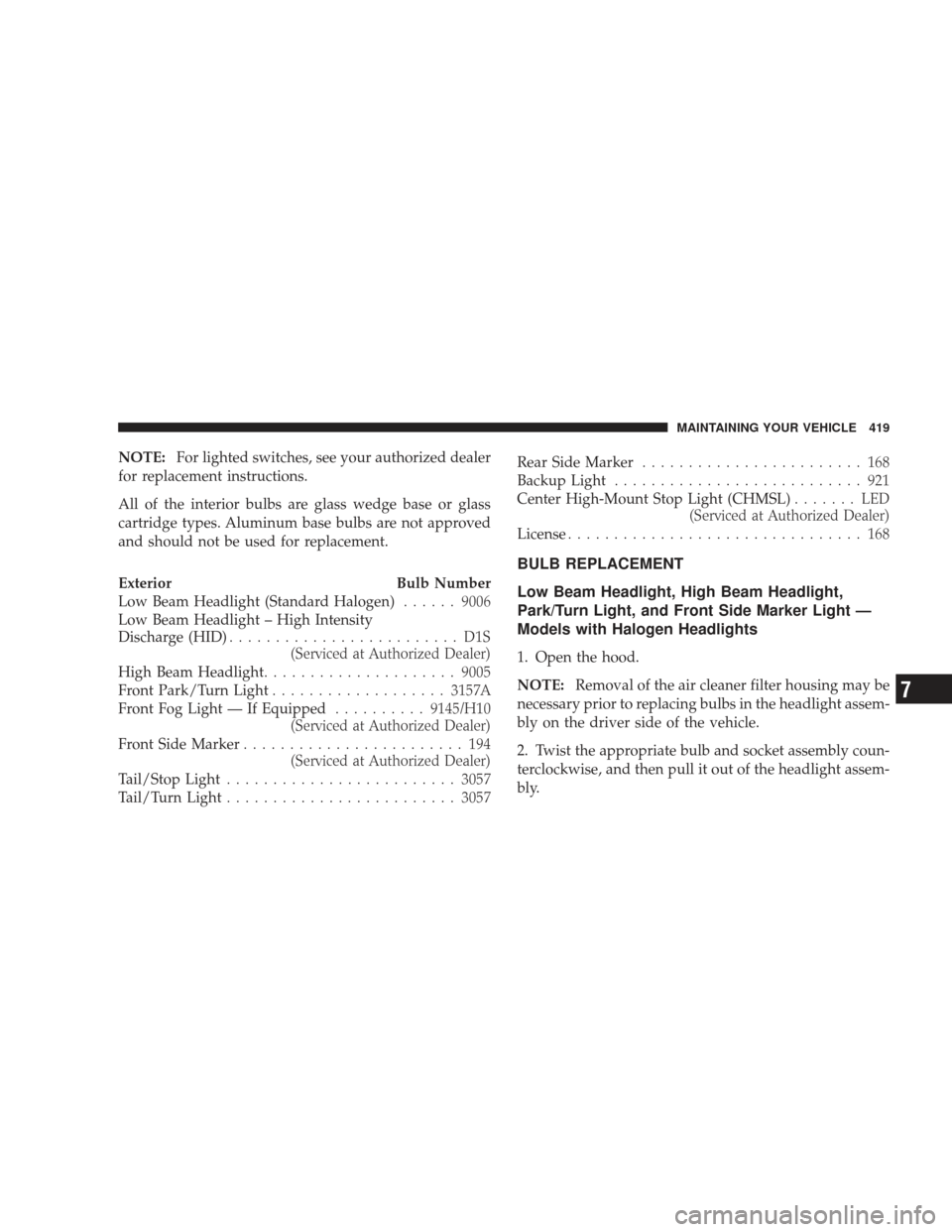
NOTE:For lighted switches, see your authorized dealer
for replacement instructions.
All of the interior bulbs are glass wedge base or glass
cartridge types. Aluminum base bulbs are not approved
and should not be used for replacement.
Exterior Bulb Number
Low Beam Headlight (Standard Halogen) ......9006
Low Beam Headlight – High Intensity
Discharge (HID) ......................... D1S
(Serviced at Authorized Dealer)
High Beam Headlight ..................... 9005
Front Park/Turn Light ................... 3157A
Front Fog Light — If Equipped ..........9145/H10
(Serviced at Authorized Dealer)
Front Side Marker ........................ 194
(Serviced at Authorized Dealer)
Tail/Stop Light ......................... 3057
Tail/Turn Light ......................... 3057Rear Side Marker
........................ 168
Backup Light ........................... 921
Center High-Mount Stop Light (CHMSL) ....... LED
(Serviced at Authorized Dealer)
License ................................ 168
BULB REPLACEMENT
Low Beam Headlight, High Beam Headlight,
Park/Turn Light, and Front Side Marker Light —
Models with Halogen Headlights
1. Open the hood.
NOTE: Removal of the air cleaner filter housing may be
necessary prior to replacing bulbs in the headlight assem-
bly on the driver side of the vehicle.
2. Twist the appropriate bulb and socket assembly coun-
terclockwise, and then pull it out of the headlight assem-
bly.
MAINTAINING YOUR VEHICLE 419
7
Page 422 of 484
CAUTION!
Do not touch the new bulb with your fingers. Oil
contamination will severely shorten bulb life. If the
bulb comes in contact with an oily surface, clean the
bulb with rubbing alcohol.
3. Disconnect the bulb from the socket assembly and
install the replacement bulb.
4. Reinstall the bulb and socket assembly into the head-
light assembly, and then turn it clockwise.
1 — High Beam Headlight Bulb
2 — Low Beam Headlight Bulb
420 MAINTAINING YOUR VEHICLE