Page 385 of 484
TRIP ODOMETER button to turn off the message. If the
problem continues, the message will appear the next time
the vehicle is started.
A loose, improperly installed, or damaged fuel filler cap
may also turn on the MIL.
EMISSIONS INSPECTION AND MAINTENANCE
PROGRAMS
In some localities, it may be a legal requirement to pass
an inspection of your vehicle’s emissions control system.
Failure to pass could prevent vehicle registration.For states that require an Inspection and Mainte-
nance (I/M), this check verifies the Malfunction
Indicator Light (MIL) is functioning and is not on
when the engine is running, and that the OBD II system
is ready for testing.
Normally, the OBD II system will be ready. The OBD II
system may notbe ready if your vehicle was recently serviced, recently had a dead battery or a battery replace-
ment. If the OBD II system should be determined not
ready for the I/M test, your vehicle may fail the test.
Your vehicle has a simple ignition key-actuated test,
which you can use prior to going to the test station. To
check if your vehicle’s OBD II system is ready, you must
do the following:
1. Insert your ignition key into the ignition switch.
2. Turn the ignition to the ON position, but do not crank
or start the engine.
3. If you crank or start the engine, you will have to start
this test over.
4. As soon as you turn your key to the ON position, you
will see the MIL symbol come on as part of a normal bulb
check.
MAINTAINING YOUR VEHICLE 383
7
Page 405 of 484

Master Cylinder - Brake Fluid Level Check
Check the fluid level in the master cylinder immediately
if the brake system warning light indicates system fail-
ure.
Check the fluid level in the master cylinder when per-
forming underhood services.
Clean the top of the master cylinder area before removing
the cap. Add fluid to bring the level up to the top of the
“FULL” mark on the side of the master cylinder reservoir.
Overfilling of fluid is not recommended because it may
cause leaking in the system.
Add enough fluid to bring the level up to the require-
ments described on the brake fluid reservoir. With disc
brakes, fluid level can be expected to fall as the brake
pads wear. However, low fluid level may be caused by a
leak and a checkup may be needed.Use only manufacturer’s recommended brake fluid. Re-
fer to “Fluids, Lubricants, and Genuine Parts” in this
section for the correct fluid type.
WARNING!
•Overfilling the brake fluid reservoir can result in
spilling brake fluid on hot engine parts and the
brake fluid catching fire.
•Use of a brake fluid that may have a lower initial
boiling point, or is unidentified as to specification,
may result in sudden brake failure during hard
prolonged braking. You could have an accident.
Use only brake fluid that has been in a tightly closed
container to avoid contamination from foreign matter or
moisture.
MAINTAINING YOUR VEHICLE 403
7
Page 408 of 484
The front differential fill plug is located on the outer
cover near the halfshaft attachment. To inspect the differ-
ential fluid level, remove the fill plug. The fluid level
should be even with or slightly below the bottom of the
hole.
Fluid Changes
Refer to the “Maintenance Schedule” in Section 8 for
proper maintenance intervals.
Appearance Care and Protection from Corrosion
Protection of Body and Paint from Corrosion
Vehicle body care requirements vary according to geo-
graphic locations and usage. Chemicals that make roads
passable in snow and ice, and chemicals that are sprayed
on trees and road surfaces during other seasons, are
highly corrosive to the metal in your vehicle. Outside
parking, which exposes your vehicle to airborne contami-
nants, road surfaces on which the vehicle is operated,extreme hot or cold weather and other extreme condi-
tions will have an adverse effect on paint, metal trim, and
underbody protection.
The following maintenance recommendations will enable
you to obtain maximum benefit from the corrosion
resistance built into your vehicle.
What Causes Corrosion?
Corrosion is the result of deterioration or removal of
paint and protective coatings from your vehicle.
The most common causes are:
•Road salt, dirt, and moisture accumulation.
•Stone and gravel impact.
•Insects, tree sap, and tar.
•Salt in the air near seacoast localities.
•Atmospheric fallout/industrial pollutants.
406 MAINTAINING YOUR VEHICLE
Page 411 of 484
Your leather upholstery can be best preserved by regular
cleaning with a damp soft cloth. Small particles of dirt
can act as an abrasive and damage the leather upholstery
and should be removed promptly with a damp cloth.
Stubborn soils can be removed easily with a soft cloth
and MOPAR�Total Clean or equivalent. Care should be
taken to avoid soaking your leather upholstery with any
liquid. Please do not use polishes, oils, cleaning fluids,
solvents, detergents, or ammonia-based cleaners to clean
your leather upholstery. Application of a leather condi-
tioner is not required to maintain the original condition.
WARNING!
Do not use volatile solvents for cleaning purposes.
Many are potentially flammable, and if used in
closed areas they may cause respiratory harm.
Cleaning Headlights
Your vehicle has plastic headlights that are lighter and
less susceptible to stone breakage than glass headlights.
Plastic is not as scratch resistant as glass and therefore
different lens cleaning procedures must be followed.
To minimize the possibility of scratching the lenses and
reducing light output, avoid wiping with a dry cloth. To
remove road dirt, wash with a mild soap solution fol-
lowed by rinsing.
Do not use abrasive cleaning components, solvents, steel
wool or other aggressive material to clean the lenses.
Glass Surfaces
All glass surfaces should be cleaned on a regular basis
with MOPAR� Glass Cleaner or any commercial
household-type glass cleaner. Never use an abrasive type
cleaner. Use caution when cleaning the inside rear win-
dow equipped with electric defrosters or the right rear
MAINTAINING YOUR VEHICLE 409
7
Page 418 of 484
Cavity Car-tridge
FuseMini-
Fuse
Description
16———
17 — 20 Amp YellowCluster
18 — 20 Amp YellowSelectable Power Outlet
19 — 10 Amp RedStop Lights
20———
21———
22———
23———
24———
25———
26———Cavity Car- tridge
FuseMini-
Fuse
Description
27 — 10 Amp RedOccupant Restraint Con-
troller (ORC)
28 — 10 Amp RedIgnition Run
29 — 5 Amp OrangeCluster/Electronic Sta-
bility Program (ESP) - if
equipped/Powertrain
Control Module (PCM)/
STOP LIGHT Switch
30 — 10 Amp RedDoor Modules/Power
Mirrors/Steering Con-
trol Module (SCM)
31———
32———
33———
34———
416 MAINTAINING YOUR VEHICLE
Page 419 of 484
Cavity Car-tridge
FuseMini-
Fuse
Description
35 — 5 Amp OrangeAntenna Module - if
equipped/Power Mir-
rors
36 — 20 Amp YellowHands-Free Phone - if
equipped/Video Moni-
tor - if equipped/Radio
37 — 15 Amp BlueTransmission
38 — 10 Amp RedCargo Light/Satellite
Receiver (SDARS) Video
- if equipped/Vehicle
Information Module - if
equipped
39 — 10 Amp RedHeated Mirrors - if
equippedCavity Car-
tridge
FuseMini-
Fuse
Description
40 — 5 Amp OrangeAuto Inside Rearview
Mirror - if equipped/
Heated Seats - if
equipped/Switch Bank
41 — 10 Amp RedAC Heater Control/
Headlights/Tire Pres-
sure Monitoring - if
equipped
42 30 Amp Pink— Front Blower Motor
43 30 Amp Pink— Rear Window Defroster
44 20 Amp Blue— Amplifier - if equipped/
Sunroof - if equipped
MAINTAINING YOUR VEHICLE 417
7
Page 420 of 484
*Cavities 11, 12, and 13 contain self-resetting fuses
(circuit breakers) that are only serviceable by an autho-
rized dealer. The cluster and the driver seat switch (if
equipped) are fused by the 25-Amp circuit breaker in
Cavity 11. The passenger seat switch (if equipped) is
fused by the 25-Amp circuit breaker in Cavity 12. The
door modules, the driver power window switch, and the
passenger power window switch are fused by the 25-
Amp circuit breaker in Cavity 13. If you experience
temporary or permanent loss of these systems, see your
authorized dealer for service.
VEHICLE STORAGE
If you are leaving your vehicle dormant for more than
21 days, you may want to take these steps to protect your
battery.
•Disconnect the negative cable from the battery.
•Anytime you store your vehicle, or keep it out of
service (i.e., vacation) for two weeks or more, run the air conditioning system at idle for about five minutes
in the fresh air and high blower setting. This will
ensure adequate system lubrication to minimize the
possibility of compressor damage when the system is
started again.
REPLACEMENT LIGHT BULBS
Interior
Bulb Number
Rear Courtesy/Reading Lights .............. W5W
Rear Compartment (Trunk) Light ............. 562
Overhead Console Reading Lights ............. 578
Visor Vanity Lights ..................... A6220
Glove Box Light ......................... 194
Door Courtesy .......................... 562
Shift Indicator Light ................. JKLE14140
Optional Door Map Pocket / Cupholder
Lighting ........ LED (Serviced at Authorized Dealer)
418 MAINTAINING YOUR VEHICLE
Page 421 of 484
NOTE:For lighted switches, see your authorized dealer
for replacement instructions.
All of the interior bulbs are glass wedge base or glass
cartridge types. Aluminum base bulbs are not approved
and should not be used for replacement.
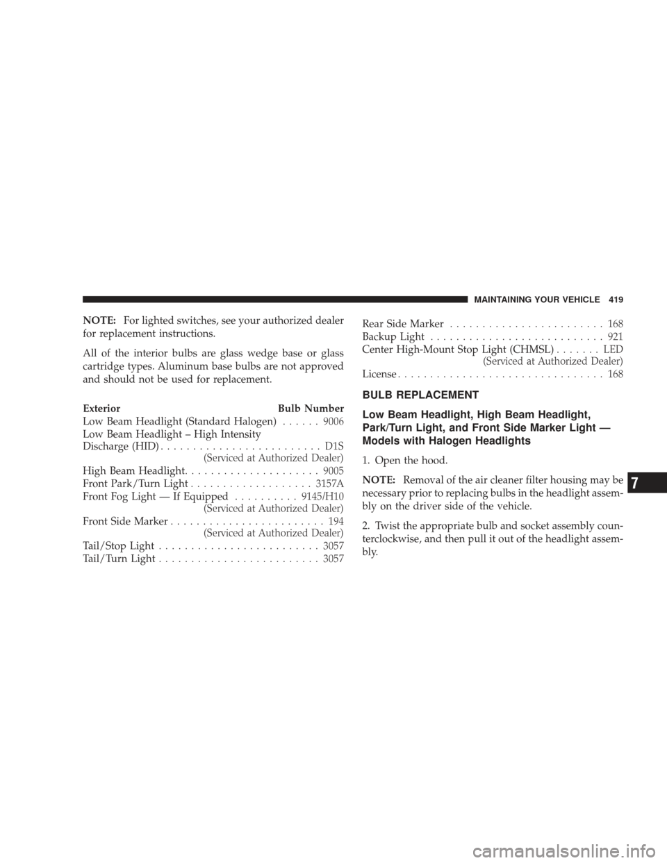
Exterior Bulb Number
Low Beam Headlight (Standard Halogen) ......9006
Low Beam Headlight – High Intensity
Discharge (HID) ......................... D1S
(Serviced at Authorized Dealer)
High Beam Headlight ..................... 9005
Front Park/Turn Light ................... 3157A
Front Fog Light — If Equipped ..........9145/H10
(Serviced at Authorized Dealer)
Front Side Marker ........................ 194
(Serviced at Authorized Dealer)
Tail/Stop Light ......................... 3057
Tail/Turn Light ......................... 3057Rear Side Marker
........................ 168
Backup Light ........................... 921
Center High-Mount Stop Light (CHMSL) ....... LED
(Serviced at Authorized Dealer)
License ................................ 168
BULB REPLACEMENT
Low Beam Headlight, High Beam Headlight,
Park/Turn Light, and Front Side Marker Light —
Models with Halogen Headlights
1. Open the hood.
NOTE: Removal of the air cleaner filter housing may be
necessary prior to replacing bulbs in the headlight assem-
bly on the driver side of the vehicle.
2. Twist the appropriate bulb and socket assembly coun-
terclockwise, and then pull it out of the headlight assem-
bly.
MAINTAINING YOUR VEHICLE 419
7