Page 139 of 534
•Echo at the far end can sometimes be reduced by
lowering the in-vehicle audio volume.
•In a convertible vehicle, system performance may be
compromised with the convertible top down.
Bluetooth�Communication Link
Cellular phones have been found to lose connection to
the UConnect�system. When this happens, the connec-
tion can generally be re-established by switching the
phone off/on. Your cell phone is recommended to remain
in Bluetooth�ON mode.
Power-Up
After switching the ignition key from OFF to either ON
or ACC position, or after a language change, you must
wait at least five seconds prior to using the system.
UNDERSTANDING THE FEATURES OF YOUR VEHICLE 137
3
ProCarManuals.com
Page 144 of 534
Voice Commands
Primary Alternate(s)
language
list names
list phones
mobile
mute
mute off
new entry
no
pager
pair a phone
phone pairing pairing
phonebook phone book
previous
record again
redialVoice Commands
Primary Alternate(s)
return to main menu return or main menu
select phone select
send
set up phone settings or phone
set up
towing assistance
transfer call
UConnect�Tutorial
try again
voice training
work
yes
142 UNDERSTANDING THE FEATURES OF YOUR VEHICLE
ProCarManuals.com
Page 156 of 534
WARNING!
In the event of a collision you could be injured if the
seat is not fully latched.
Swivel ’n Go Premium Seating — If Equipped
Premium second row Swivel ’n Go Seating features
include:
•A table that installs between the second and third row
seats. The table disassembles and stows in the hidden
second row floor storage bin
•Seats rotate to face forward or rearward
•Seat belts are integrated into the swivel seats
•Dual folding armrests
•A side storage pocket that will accommodate a phone
or handheld game
•Seats are removable
To swivel the seat: Pull the lower handle on the outboard
side of the seat and push the side of the seatback to begin
Swivel ’n Go Seating Features
1 — Moveable Armrest 4 — Fore-Aft Adjustment
2 — Seatback Release 5 — Seat Release
3 — Swivel Release 154 UNDERSTANDING THE FEATURES OF YOUR VEHICLE
ProCarManuals.com
Page 209 of 534

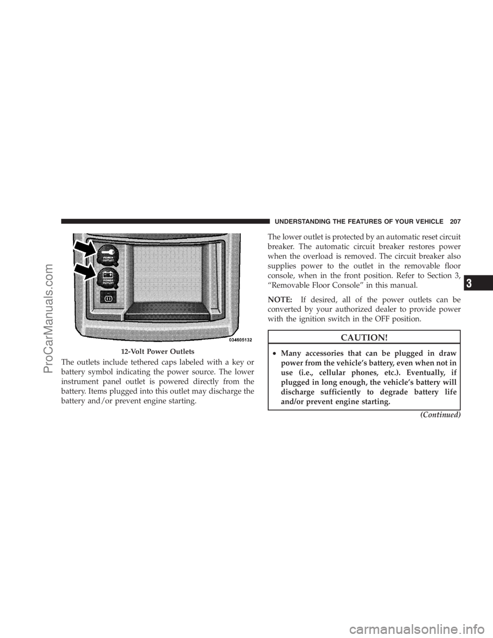
The outlets include tethered caps labeled with a key or
battery symbol indicating the power source. The lower
instrument panel outlet is powered directly from the
battery. Items plugged into this outlet may discharge the
battery and/or prevent engine starting.The lower outlet is protected by an automatic reset circuit
breaker. The automatic circuit breaker restores power
when the overload is removed. The circuit breaker also
supplies power to the outlet in the removable floor
console, when in the front position. Refer to Section 3,
“Removable Floor Console” in this manual.
NOTE:If desired, all of the power outlets can be
converted by your authorized dealer to provide power
with the ignition switch in the OFF position.
CAUTION!
•Many accessories that can be plugged in draw
power from the vehicle’s battery, even when not in
use (i.e., cellular phones, etc.). Eventually, if
plugged in long enough, the vehicle’s battery will
discharge sufficiently to degrade battery life
and/or prevent engine starting.
(Continued)12-Volt Power Outlets
UNDERSTANDING THE FEATURES OF YOUR VEHICLE 207
3
ProCarManuals.com
Page 221 of 534
•Large console center storage will store headphones for
the available rear DVD entertainment system or other
items
•12-Volt DC power outlet provides continuous power
inside the console for cell phones or other electronics.
•Rear occupant accessible
•Multiple adjustments
•Removable from vehicle for additional floor space.
Premium Console Features
1 — Top Release 3 — Console Release
2 — Center ReleaseUNDERSTANDING THE FEATURES OF YOUR VEHICLE 219
3
ProCarManuals.com
Page 233 of 534

▫Play Mode......................... 288
▫List Or Browse Mode.................. 289
�Satellite Radio — If Equipped
(REN/REQ/RER/RES/REU Radios Only)..... 291
▫System Activation.................... 292
▫Electronic Serial Number/Sirius
Identification Number (ESN/SID)......... 292
▫Selecting Satellite Mode................ 293
▫Satellite Antenna..................... 293
▫Reception Quality.................... 293
▫Operating Instructions — Satellite Mode.... 293
▫Operating Instructions — Hands-Free Phone
(If Equipped)........................ 296▫Operating Instructions — Video
Entertainment System (VES)™
(If Equipped)........................ 296
�Sirius Backseat TV™ — If Equipped........ 297
�Video Entertainment System (VES)™ — If
Equipped............................ 297
�Remote Sound System Controls —
If Equipped........................... 299
▫Radio Operation..................... 299
▫CD Player.......................... 300
�CD/DVD Maintenance.................. 300
�Radio Operation And Cellular Phones....... 301
UNDERSTANDING YOUR INSTRUMENT PANEL 231
4
ProCarManuals.com
Page 253 of 534

NOTE:Magnetic and battery powered devices, (such as
cell phones, IPOD’s, radar detectors, PDA’s and laptops)
should be kept away from the top of the instrument
panel. This is where the compass module is located and
such devices may interfere and cause false compass
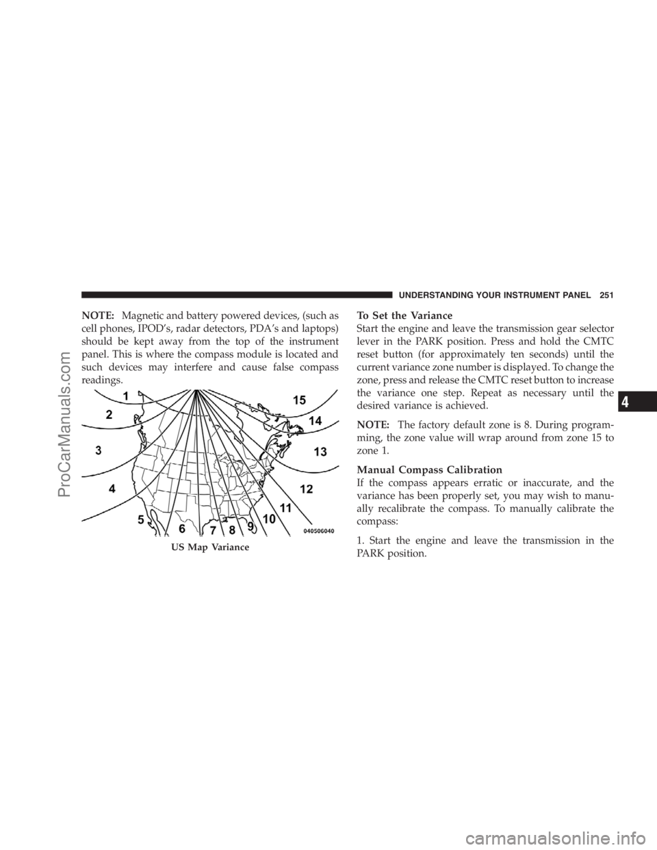
readings.To Set the Variance
Start the engine and leave the transmission gear selector
lever in the PARK position. Press and hold the CMTC
reset button (for approximately ten seconds) until the
current variance zone number is displayed. To change the
zone, press and release the CMTC reset button to increase
the variance one step. Repeat as necessary until the
desired variance is achieved.
NOTE:The factory default zone is 8. During program-
ming, the zone value will wrap around from zone 15 to
zone 1.
Manual Compass Calibration
If the compass appears erratic or inaccurate, and the
variance has been properly set, you may wish to manu-
ally recalibrate the compass. To manually calibrate the
compass:
1. Start the engine and leave the transmission in the
PARK position.
US Map Variance
UNDERSTANDING YOUR INSTRUMENT PANEL 251
4
ProCarManuals.com
Page 260 of 534
Compass Variance
Compass Variance is the difference between Magnetic
North and Geographic North. To compensate for the
differences, the variance should be set for the zone where
the vehicle is driven, per the zone map. Once properly
set, the compass will automatically compensate for the
differences, and provide the most accurate compass
heading. For the most accurate compass performance, the
compass must be set using the following steps.
NOTE:Keep magnetic materials away from the top of
the instrument panel, such as IPODs, Cell Phones, Lap-
tops and Radar Detectors. This is where the compass
module is located, and it can cause interference with the
compass sensor, and it may give false readings.1. Turn the ignition switch ON.
2. Press and hold the compass button for approximately
two seconds.
3. Press the STEP button until “Compass Variance” mes-
sage, and the last variance zone number, displays in the
EVIC.
258 UNDERSTANDING YOUR INSTRUMENT PANEL
ProCarManuals.com