Page 237 of 411
4. Fold the right rear passenger seat rearward into the
upright position. The rear tether anchors should engage
the hooks located on the back or the subwoofer.
5. Check the subwoofer for being securely fastened to the
seatback.
WARNING!
Always remove the subwoofer from the vehicle
whenever the tether anchors behind the subwoofer
are required for proper installation of a child re-
straining device. In the event of an accident, or under
severe vehicle maneuvers, leaving the subwoofer
unsecured in the vehicle could result in serious or
fatal injury to anyone in the vehicle.Removing Subwoofer
1. Fold the right rear passenger seatback forward to
unlatch the subwoofer.
2. Disconnect the electrical connector.
3. Open the liftgate and remove the subwoofer.
UNDERSTANDING YOUR INSTRUMENT PANEL 235
4
Page 245 of 411

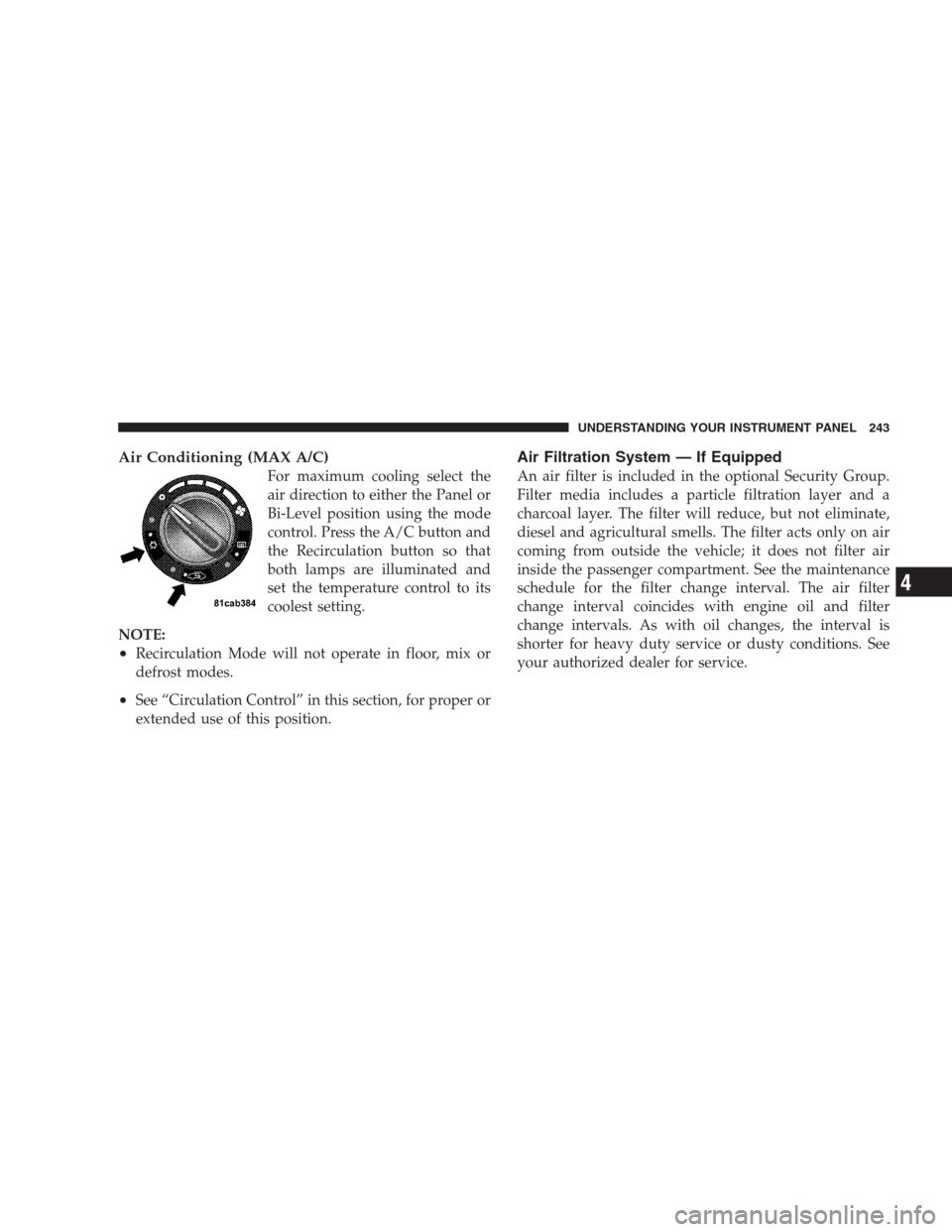
Air Conditioning (MAX A/C)
For maximum cooling select the
air direction to either the Panel or
Bi-Level position using the mode
control. Press the A/C button and
the Recirculation button so that
both lamps are illuminated and
set the temperature control to its
coolest setting.
NOTE:
•Recirculation Mode will not operate in floor, mix or
defrost modes.
•See “Circulation Control” in this section, for proper or
extended use of this position.
Air Filtration System — If Equipped
An air filter is included in the optional Security Group.
Filter media includes a particle filtration layer and a
charcoal layer. The filter will reduce, but not eliminate,
diesel and agricultural smells. The filter acts only on air
coming from outside the vehicle; it does not filter air
inside the passenger compartment. See the maintenance
schedule for the filter change interval. The air filter
change interval coincides with engine oil and filter
change intervals. As with oil changes, the interval is
shorter for heavy duty service or dusty conditions. See
your authorized dealer for service.
UNDERSTANDING YOUR INSTRUMENT PANEL 243
4
Page 316 of 411

(D) After Injecting TIREFIT Sealant:
1. Allow the air pump to inflate the tire to the pressure
indicated on the tire pressure label on the driver-side
latch pillar. Check the pressure in the tire by looking at
the Pressure Gauge (2).
•If the tire inflates to at least 26 psi (1.8 bar) within
15 minutes, proceed to Step 2 of this procedure.
•If tire fails to inflate to 26 psi (1.8 bar) within
15 minutes, perform the procedure steps described
under “(G) Distributing TIREFIT Sealant to Better
Enable Tire Inflation.”
2. Press the Air Pump Power Button (3) to
turn OFF the TIREFIT kit.3. Remove the Speed Limit sticker from the top of the
Sealant Bottle (1) and place the sticker on the steering
wheel.
4. Disconnect the Clear Sealant Hose (7) from the valve
stem, reinstall the Yellow Cap on the fitting at the end of
the hose, and place the TIREFIT kit in the vehicle.
CAUTION!
Failure to reinstall the Yellow Cap on the fitting at
the end of the Clear Sealant Hose (7) can result in
sealant contacting your skin, clothing, and the vehi-
cle’s interior. It can also result in sealant contacting
internal TIREFIT kit components causing permanent
damage to the kit.
(E) Securing TIREFIT Sealant in the Tire
Drive the vehicle for approximately 5 miles (8 km) to
ensure distribution of the TIREFIT Sealant within the tire.
314 WHAT TO DO IN EMERGENCIES
Page 317 of 411

WARNING!
TIREFIT is not a permanent flat tire repair. Have the
tire inspected and repaired or replaced after using
TIREFIT. Do not exceed 55 mph (90 km/h) until
having the tire repaired or replaced. Failure to follow
this warning can result in injuries that are serious or
fatal to you, your passengers, and others around you.
(F) After Securing TIREFIT Sealant in the Tire:
1. Turn the Mode Select knob (4) to the Air
Mode position.
2. Uncoil the Black Air Pump Hose (6) and connect it to
the valve stem.
3. Check the pressure in the tire by reading the Pressure
Gauge (2).
•If the pressure is less than 19 psi (1.3 bar), the tire is
too badly damaged. Do not attempt to drive the
vehicle further. Call for assistance.
•If the pressure is equal to or greater than 19 psi
(1.3 bar), but less than the level indicated on the tire
pressure label, proceed to Step 4 of this procedure.
•If the pressure is at the level indicated on the tire
pressure label on the driver-side latch pillar, proceed
to Step 5 of this procedure.
4. Inflate the tire to the pressure indicated on the tire
pressure label on the driver-side latch pillar.
5. Disconnect the TIREFIT kit from the valve stem and
then reinstall the cap on the valve stem.
6. Place the TIREFIT kit in its proper storage area in the
vehicle.
WHAT TO DO IN EMERGENCIES 315
6
Page 323 of 411

CAUTION!
DO NOT flat tow any vehicle equipped with an
automatic transmission. Damage to the drivetrain
will result.
Manual Transaxle
•
Front Wheel Drive (FWD) or All Wheel Drive (AWD)
vehicles can be flat towed (all four wheels on the
ground) with the transmission in NEUTRAL.
•FWD vehicles can be towed with the front or rear
wheels elevated.
•FWD or AWD vehicles can be towed on a flatbed truck
(all wheels off the ground).
All Transaxles
If it is necessary to use the accessories while being towed
(wipers, defrosters, etc.), the key must be in the ON
position, not the ACC position. Make certain the trans-
mission remains in NEUTRAL.
CAUTION!
•If the vehicle being towed requires steering, the
ignition switch must be in the ACC position, not
in the LOCK position.
•Do not attempt to use sling type equipment when
towing. When securing the vehicle to a flat bed
truck, do not attach to front or rear suspension
components. Damage to your vehicle may result
from improper towing.
WHAT TO DO IN EMERGENCIES 321
6
Page 354 of 411
Replace the seat belts if they appear frayed or worn or if
the buckles do not work properly.
Dry with a soft cloth.
FUSES
Integrated Power Module
The Integrated Power Module (IPM) is located in the
engine compartment near the air cleaner assembly. This
center contains cartridge fuses and mini-fuses. A label
that identifies each component may be printed on the
inside of the cover. Refer to “Engine Compartment” in
this section of the Owner’s Manual for the underhood
location of the Integrated Power Module (IPM).
Cavity Cartridge
FuseMini-
FuseDescription
1 Empty Empty
2 15 Amp
Lt. BlueAWD/4WD ECU
Feed
Cavity Cartridge
FuseMini-
FuseDescription
3 10 Amp
RedCHMSL Brake Switch
Feed
4 10 Amp
RedIgnition Switch Feed
5 20 Amp
YellowTrailer Tow
6 10 Amp
RedIOD Sw/Pwr Mir/
Ocm Steering Cntrl
Sdar/Hands-Free
Phone
7 30 Amp
GreenIOD Sense1
8 30 Amp
GreenIOD Sense2
9 40 Amp
GreenPower Seats
352 MAINTAINING YOUR VEHICLE
Page 394 of 411

ABS (Anti-Lock Brake System).............. 261
Adding Engine Coolant (Antifreeze).......... 341
Adding Fuel........................... 301
Additives, Fuel......................... 299
Air Cleaner, Engine (Engine Air Cleaner Filter) . . . 332
Air Conditioner Maintenance............... 335
Air Conditioning Controls................. 238
Air Conditioning, Operating Tips............ 244
Air Conditioning Refrigerant............... 335
Air Conditioning System................238,335
Air Pressure, Tires....................... 280
Airbag................................ 48
Airbag Deployment....................... 56
Airbag Light.......................58,71,165
Airbag Maintenance....................... 58
Airbag, Side............................ 55
Airbag, Window (Side Curtain)............... 49
Alarm System (Security Alarm)............19,165
Alterations/Modifications, Vehicle............. 7Antenna, Satellite Radio................... 230
Antifreeze (Engine Coolant)...........340,359,360
Capacities........................... 359
Disposal............................ 343
Anti-Lock Brake System (ABS).............. 261
Anti-Lock Warning Light.................. 173
Anti-Theft Security Alarm (Theft Alarm)........ 19
Appearance Care........................ 347
Assistance Towing........................ 96
Automatic Dimming Mirror................. 78
Automatic Door Locks...................28,29
Automatic Transaxle...................... 12
Battery............................... 333
Keyless Transmitter Replacement (RKE)....... 26
Beverage Cooler........................ 154
Body Mechanism Lubrication............... 336
B-Pillar Location........................ 275
Brake Assist System...................... 264
392 INDEX
Page 401 of 411

Lead Free Gasoline...................... 296
Life of Tires............................ 284
Liftgate (Sedan).......................... 34
Liftgate Window Wiper/Washer............. 152
Light Bulbs............................ 355
Lights..............................72,122
Airbag..........................58,71,165
Anti-Lock........................... 173
Back-Up............................. 357
Brake Warning........................ 169
Bulb Replacement...................... 356
Cargo .............................. 147
Center Mounted Stop................... 358
Daytime Running...................... 127
Dimmer Switch, Headlight............... 122
Electronic Stability Program (ESP)
Indicator...........................266,269
Engine Temperature Warning.............. 166
Fog ..........................124,171,356Headlight Switch...................... 123
Headlights........................... 123
High Beam Indicator.................... 174
Instrument Cluster..................... 123
License............................. 357
Lights On Reminder.................... 124
Low Fuel............................ 165
Malfunction Indicator (Check Engine)........ 173
Map Reading......................... 126
Oil Pressure.......................... 166
Seat Belt Reminder..................... 166
Security Alarm (Theft Alarm).............. 20
Theft Alarm (Security Alarm).............. 165
Tire Pressure Monitoring (TPMS)........... 171
Traction Control....................... 266
Turn Signal.....................122,124,357
Voltage............................. 165
Warning (Instrument Cluster Description)..... 164
INDEX 399
10