Page 411 of 543

•When replacing tires, refer to “Tires–General Informa-
tion” in this section for proper tire replacement proce-
dures. Replacing tires with a higher load carrying
capacity will not increase the vehicle’s GVWR and
GAWR limits.
Towing Requirements — Trailer Brakes
•
Donot interconnect the hydraulic brake system or
vacuum system of your vehicle with that of the trailer.
This could cause inadequate braking and possible
personal injury.
•An electronically actuated trailer brake controller is
required when towing a trailer with electronically
actuated brakes. When towing a trailer equipped with
a hydraulic surge actuated brake system, an electronic
brake controller is not required.
•Trailer brakes are recommended for trailers over
1,000 lbs (454 kg) and required for trailers in excess of
2,000 lbs (907 kg).
CAUTION!
If the trailer weighs more than 1,000 lbs (454 kg)
loaded, it should have its own brakes and they
should be of adequate capacity. Failure to do this
could lead to accelerated brake lining wear, higher
brake pedal effort, and longer stopping distances.
WARNING!
•Do not connect trailer brakes to your vehicle’s
hydraulic brake lines. It can overload your brake
system and cause it to fail. You might not have
brakes when you need them and could have an
accident.
(Continued)
5
STARTING AND OPERATING 409
Page 412 of 543
WARNING! (Continued)
•Towing any trailer will increase your stopping
distance. When towing you should allow for addi-
tional space between your vehicle and the vehicle
in front of you. Failure to do so could result in an
accident.
Towing Requirements — Trailer Lights and Wiring
Whenever you pull a trailer, regardless of the trailer size,
stop lights and turn signals on the trailer are required for
motoring safety.
The Trailer Tow Package may include a four-pin or a
seven-pin wiring harness. Use a factory approved trailer
harness and connector.
NOTE:Do not cut or splice wiring into the vehicles
wiring harness. The electrical connections are all complete to the vehicle
but you must mate the harness to a trailer connector.
Refer to the following four-pin connector and seven-pin
connector illustrations.
Four-Pin Connector
1 — Female Pins
4 — Park
2 — Male Pin 5 — Left Stop/Turn
3 — Ground 6 — Right Stop/Turn
410 STARTING AND OPERATING
Page 413 of 543
Towing Tips
Before setting out on a trip, practice turning, stopping
and backing the trailer in an area away from heavy
traffic.
Automatic Transaxle
The DRIVE gear can be selected when towing. However,
if frequent shifting occurs while in DRIVE, move the shift
lever into third gear (with four-speed transaxle) or fifth
gear (with six-speed transaxle).
NOTE:Moving the shift lever into third gear (with
four-speed transaxle) or fifth gear (with six-speed trans-
axle) while operating the vehicle under heavy operating
conditions will improve performance and extend trans-
axle life by reducing excessive shifting and heat build up.
This action will also provide better engine braking.
The automatic transaxle fluid and filter should be
changed if you REGULARLY tow a trailer for more than
Seven-Pin Connector
1 — Battery 5 — Ground
2 — Backup Lamps 6 — Left Stop/Turn
3 — Right Stop/Turn 7 — Running Lamps
4 — Electric Brakes
5
STARTING AND OPERATING 411
Page 414 of 543
45 minutes of continuous operation. Refer to the “Main-
tenance Schedule” in Section 8 of this manual for the
proper maintenance intervals.
NOTE:
•Check the automatic transaxle fluid level before tow-
ing.
•The six-speed automatic transaxle is sealed and re-
quires an authorized dealer to check the transaxle
fluid.
Electronic Speed Control — If Equipped
•
Do not use in hilly terrain or with heavy loads.
•When using the speed control, if you experience speed
drops greater than 10 mph (16 km/h), disengage until
you can get back to cruising speed.
•Use speed control in flat terrain and with light loads to
maximize fuel efficiency.
Cooling System
To reduce potential for engine and transaxle overheating,
take the following actions:
•City Driving
When stopped for short periods of time, put the shift
lever in NEUTRAL but do not increase engine idle speed.
•Highway Driving
Reduce speed.
•Air Conditioning
Turn off temporarily.
412 STARTING AND OPERATING
Page 415 of 543
RECREATIONAL TOWING (BEHIND
MOTORHOME, ETC.)
CAUTION!
Towing this vehicle behind another vehicle (flat-
towing with all four wheels on the ground) is not
recommended.
NOTE: If the vehicle requires towing, make sure all four
wheels are off the ground.
5
STARTING AND OPERATING 413
Page 417 of 543
WHAT TO DO IN EMERGENCIES
CONTENTS
�Hazard Warning Flasher ............... 416
� If Your Engine Overheats ............... 416
� Jacking And Tire Changing .............. 418
▫ Jack Location ...................... 418 �
Jump-Starting Procedure ............... 430
� Freeing A Stuck Vehicle ................ 432
� Towing A Disabled Vehicle .............. 433
▫ Towing With The Ignition Key .......... 433
6
Page 420 of 543

JACKING AND TIRE CHANGING
WARNING!
•Getting under a jacked-up vehicle is dangerous.
The vehicle could slip off the jack and fall on you.
You could be crushed. Never get any part of your
body under a vehicle that is on a jack. If you need
to get under a raised vehicle, take it to a service
center where it can be raised on a lift.
•The jack is designed to use as a tool for changing
tires only. The jack should not be used to lift the
vehicle for service purposes. The vehicle should
be jacked on a firm level surface only. Avoid ice or
slippery areas.
•If it is necessary to retrieve the spare tire from
under the vehicle on the side of the vehicle close to
moving traffic. Pull far enough off the road to
avoid the danger of being hit.
Jack Location
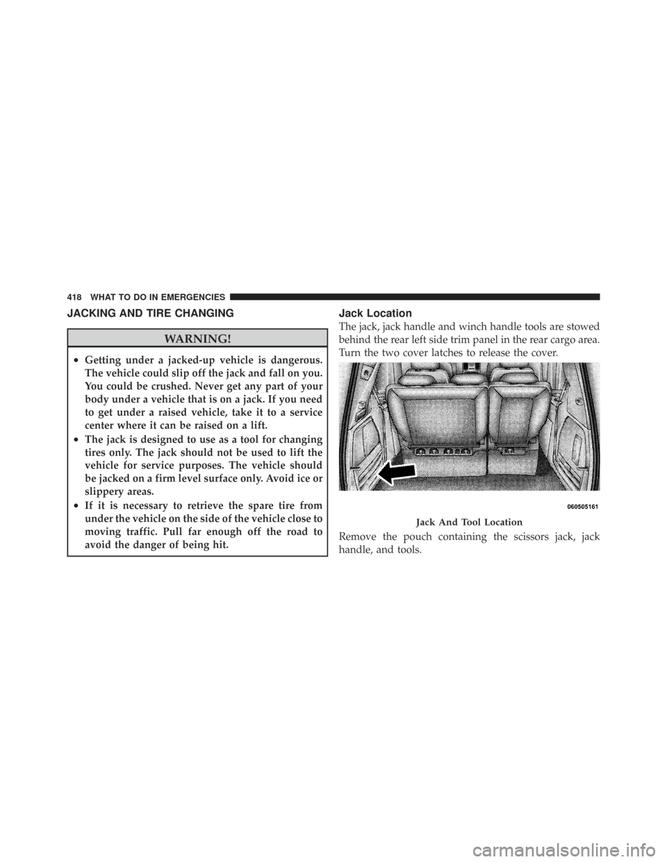
The jack, jack handle and winch handle tools are stowed
behind the rear left side trim panel in the rear cargo area.
Turn the two cover latches to release the cover.
Remove the pouch containing the scissors jack, jack
handle, and tools.
Jack And Tool Location
418 WHAT TO DO IN EMERGENCIES
Page 421 of 543
Spare Tire Removal
The spare tire is stowed inside a protective cover located
under the center of the vehicle by means of a cable winch
mechanism. The “spare tire drive” nut is located on the
floor, under a plastic cap at the front of the floor console.
NOTE:The base console, if equipped, must be removed
to raise and lower the spare tire. Refer to “Console
Features” in Section 3 for the console removal procedure.
The tool pouch contains three pieces and can be as-
sembled into a spare tire hook; to remove the compact
spare tire/cover assembly from under the vehicle, or a
Winch “T” Handle; to raise/lower the compact spare
tire/cover assembly.
Tools
1A – Spare Tire Hook (Piece 1) 2A – Winch “T” Handle (Piece 1)
1B – Spare Tire Hook (Piece 2) 2B – Winch “T” Handle (Piece 2)
1C – Spare Tire Hook (Piece 3) 2C – Winch “T” Handle (Piece 3)
6
WHAT TO DO IN EMERGENCIES 419