Page 201 of 543
WARNING!
•Drivers must be careful when backing up, even
when using the Rear Park Assist. Always check
carefully behind your vehicle, and be sure to check
for pedestrians, animals, other vehicles, obstruc-
tions, or blind spots before backing up. You are
responsible for the safety of your surroundings
and must continue to pay attention while backing
up. Failure to do so can result in serious injury or
death.(Continued)
WARNING! (Continued)
•Before using the Rear Park Assist, it is strongly
recommended that the ball mount and hitch ball
assembly be disconnected from the vehicle, when
the vehicle is not used for towing. Failure to do so
can result in injury or damage to vehicles or
obstacles, because the hitch ball will be much
closer to the obstacle than the rear fascia when the
warning display turns the red LEDs on. Also, the
sensors could detect the ball mount and hitch ball
assembly, depending on its size and shape, giving
a false indication that an obstacle is behind the
vehicle.
3
UNDERSTANDING THE FEATURES OF YOUR VEHICLE 199
Page 202 of 543
CAUTION!
•To avoid vehicle damage, the Rear Park Assist
should only be used as a parking aid and is unable
to recognize every obstacle, including small ob-
jects. Parking curbs might be temporarily detected
or not detected at all. Obstacles located above or
below the sensors will not be detected when they
are in close proximity to the rear of the vehicle.
•To avoid vehicle damage, the vehicle must be
driven slowly when using the Rear Park Assist, to
be able to stop in time when an obstacle is
detected. It is recommended that you look over
your shoulder when using the Rear Park Assist.
NOTE:
•Ensure that the rear bumper is free of dirt and debris
to keep the system operating properly.
•Jackhammers, large trucks, and other vibrations could
affect the performance of the system.
Enabling and Disabling The Rear Park Assist
There are times when you may want to disable the Rear
Park Assist, such as when towing a trailer.
Vehicles Equipped With the Electronic Vehicle
Information Center (EVIC)
You can turn the Rear Park Assist ON or OFF through the
EVIC. For details, refer to “Personal Settings (Customer-
Programmable Features)” under “Electronic Vehicle In-
formation Center (EVIC)” in Section 4.
Vehicles Equipped With the Compass Mini-Trip
Computer (CMTC)
You can turn the Rear Park Assist ON or OFF through the
CMTC by pressing the left reset button in the instrument
cluster. Turn the ignition switch to the ON position, then
press and hold the RESET button for approximately two
seconds.
200 UNDERSTANDING THE FEATURES OF YOUR VEHICLE
Page 230 of 543
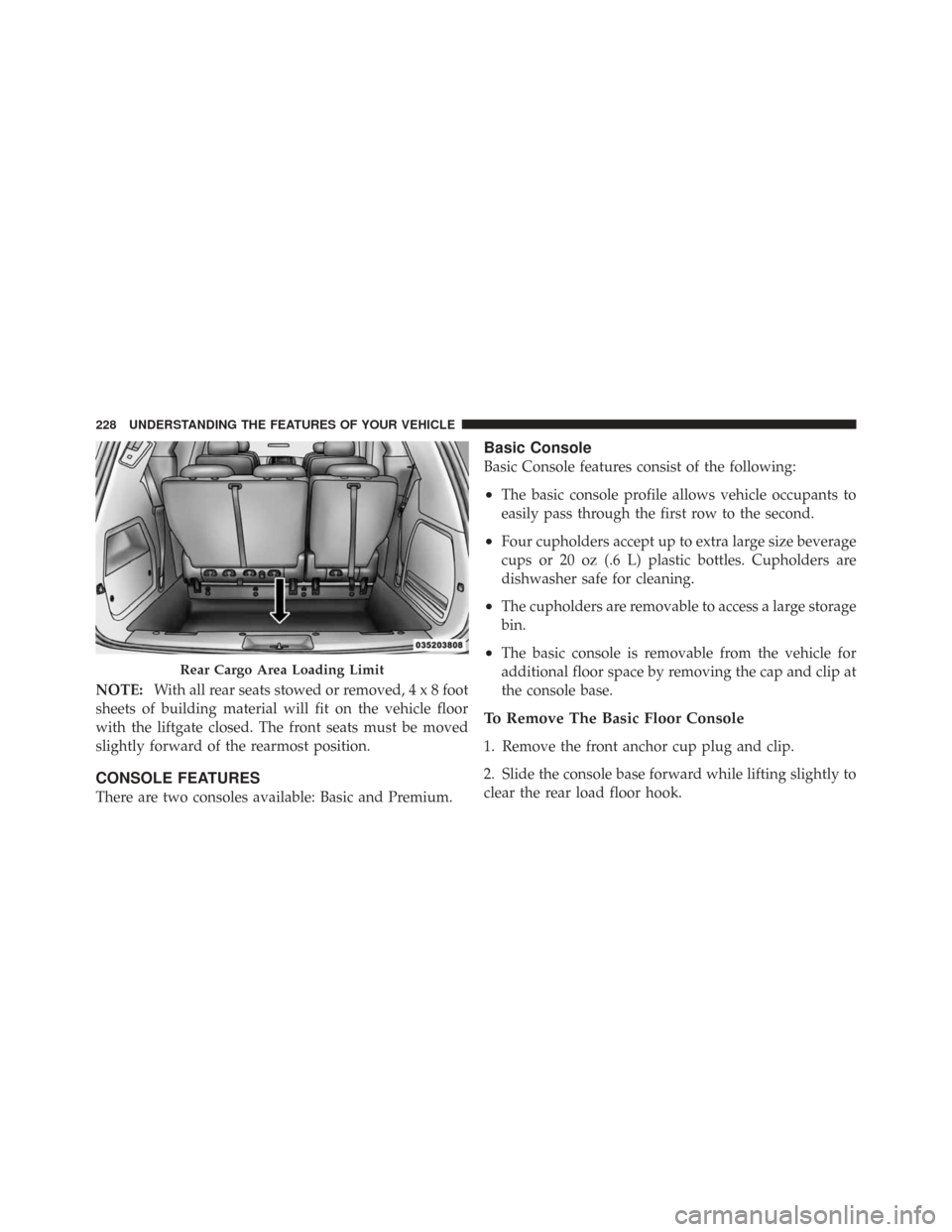
NOTE:With all rear seats stowed or removed,4x8foot
sheets of building material will fit on the vehicle floor
with the liftgate closed. The front seats must be moved
slightly forward of the rearmost position.
CONSOLE FEATURES
There are two consoles available: Basic and Premium.
Basic Console
Basic Console features consist of the following:
•The basic console profile allows vehicle occupants to
easily pass through the first row to the second.
•Four cupholders accept up to extra large size beverage
cups or 20 oz (.6 L) plastic bottles. Cupholders are
dishwasher safe for cleaning.
•The cupholders are removable to access a large storage
bin.
•The basic console is removable from the vehicle for
additional floor space by removing the cap and clip at
the console base.
To Remove The Basic Floor Console
1. Remove the front anchor cup plug and clip.
2. Slide the console base forward while lifting slightly to
clear the rear load floor hook.
Rear Cargo Area Loading Limit
228 UNDERSTANDING THE FEATURES OF YOUR VEHICLE
Page 247 of 543
INSTRUMENT CLUSTER DESCRIPTIONS
1. Fuel Gauge
The pointer shows the level of fuel in the fuel tank when
the ignition switch is in the ON position.
2. Low Fuel LightWhen the fuel level reaches approximately 2.0 gal
(7.8 L) this light will turn on, and remain on until
fuel is added.
3. Electronic Throttle Control (ETC) Light This light informs you of a problem with the
Electronic Throttle Control (ETC) system. The
light will come on when the ignition is first
turned ON and remain on briefly as a bulb
check. If the light does not come on during starting, have
the system checked by an authorized dealer.
If a problem is detected, the light will come on while the
engine is running. Cycle the ignition key when the vehicle has completely stopped and the shift lever is
placed in the PARK position, the light should turn off.
If the light remains lit with the engine running, your
vehicle will usually be drivable; however, see an autho-
rized dealer for service as soon as possible. If the light is
flashing when the engine is running, immediate service is
required and you may experience reduced performance,
an elevated/rough idle or engine stall and your vehicle
may require towing.
4. Charging System Light
This light shows the status of the electrical charg-
ing system. The light should come on when the
ignition switch is first turned ON and remain on briefly
as a bulb check. If the light stays on or comes on while
driving, turn off some of the vehicle’s non-essential
electrical devices or increase engine speed (if at idle). If
the charging system light remains on, it means that the
4
UNDERSTANDING YOUR INSTRUMENT PANEL 245
Page 254 of 543
16. High Beam IndicatorThis indicator shows that the high beam head-
lights are on. Push the multifunction lever forward
to switch the headlights to high beam, and pull toward
yourself (normal position) to return to low beam.
17. Front Fog Light Indicator — If Equipped This indicator will illuminate when the front fog
lights are on.
18. Seat Belt Reminder Light When the ignition switch is first turned ON, this
light will turn on for five to eight seconds as a bulb
check. During the bulb check, if the driver’s seat
belt is unbuckled, a chime will sound. After the bulb
check or when driving, if the driver’s seat belt remains
unbuckled, the Seat Belt Reminder Light will illuminate
and the chime will sound. Refer to “Occupant Restraints”
in Section 2 for more information. 19. Malfunction Indicator Light (MIL)
The Malfunction Indicator Light (MIL) is part of
an onboard diagnostic system, called OBD, that
monitors engine and automatic transmission con-
trol systems. The light will illuminate when the key is in
the ON position, before engine start. If the bulb does not
come on when turning the key from OFF to ON, have the
condition checked promptly.
Certain conditions such as a loose or missing gas cap,
poor fuel quality, etc., may illuminate the MIL after
engine start. The vehicle should be serviced if the light
stays on through several of your typical driving cycles. In
most situations, the vehicle will drive normally and will
not require towing.
If the MIL flashes when the engine is running, serious
conditions may exist that could lead to immediate loss of
power or severe catalytic converter damage. The vehicle
should be serviced as soon as possible if this occurs.
252 UNDERSTANDING YOUR INSTRUMENT PANEL
Page 255 of 543
20. Airbag Warning LightThis light turns on and remains on for seven
seconds as a bulb check when the ignition
switch is first turned ON. If the light is not on
during starting, stays on, or turns on while
driving, have the system inspected by an authorized
dealer as soon as possible.
21. Temperature Gauge
The temperature gauge shows engine coolant tempera-
ture. Any reading within the normal range indicates that
the engine cooling system is operating satisfactorily.
The gauge pointer will likely indicate a higher tempera-
ture when driving in hot weather, up mountain grades,
or when towing a trailer. It should not be allowed to
exceed the upper limits of the normal operating range.CAUTION!
Driving with a hot engine cooling system could
damage your vehicle. If temperature gauge reads “H”
pull over and stop the vehicle. Idle the vehicle with
the air conditioner turned off until the pointer drops
back into the normal range. If the pointer remains on
the “H” and you hear continuous chimes, turn the
engine off immediately, and call an authorized deal-
ership for service.
4
UNDERSTANDING YOUR INSTRUMENT PANEL 253
Page 315 of 543
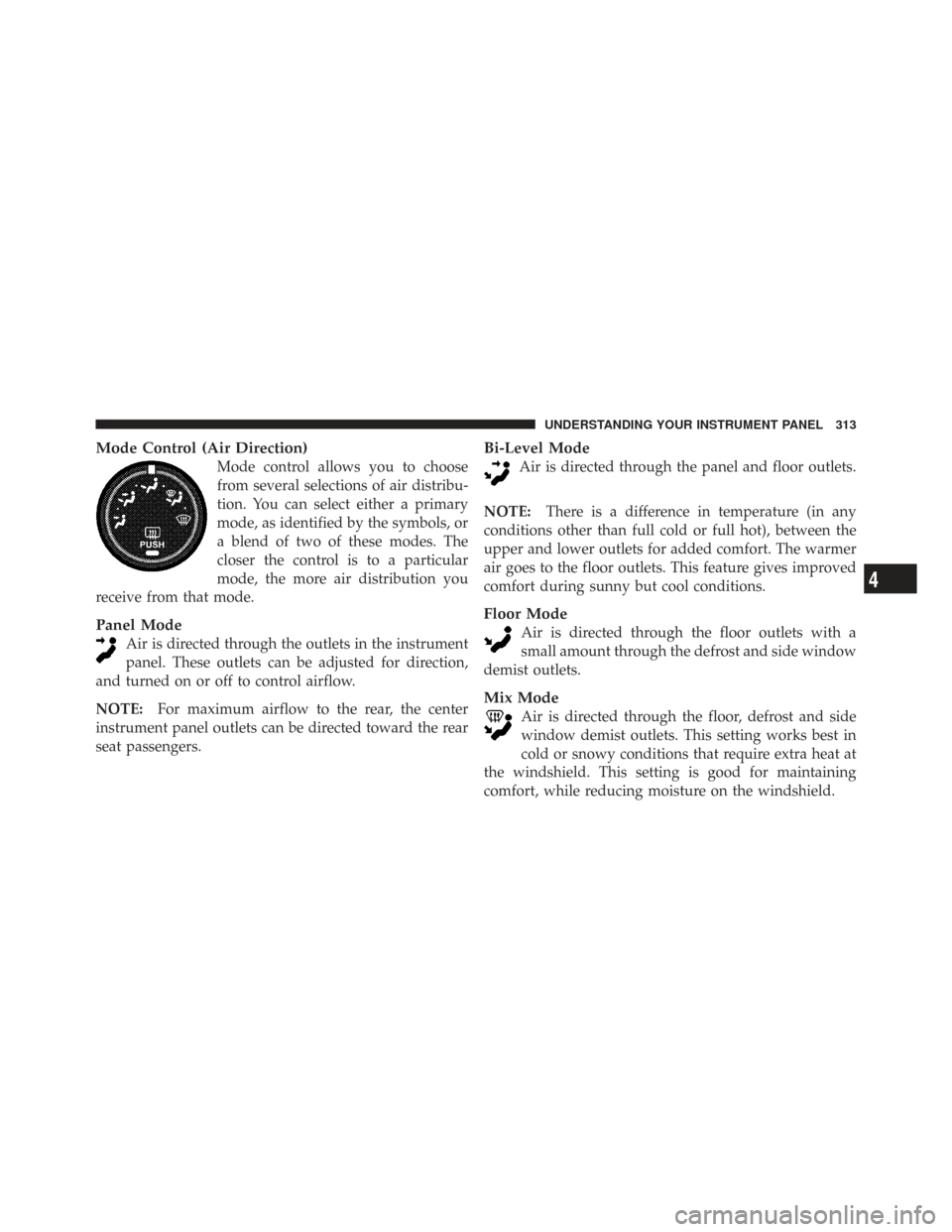
Mode Control (Air Direction)
Mode control allows you to choose
from several selections of air distribu-
tion. You can select either a primary
mode, as identified by the symbols, or
a blend of two of these modes. The
closer the control is to a particular
mode, the more air distribution you
receive from that mode.
Panel Mode
Air is directed through the outlets in the instrument
panel. These outlets can be adjusted for direction,
and turned on or off to control airflow.
NOTE: For maximum airflow to the rear, the center
instrument panel outlets can be directed toward the rear
seat passengers.
Bi-Level Mode
Air is directed through the panel and floor outlets.
NOTE: There is a difference in temperature (in any
conditions other than full cold or full hot), between the
upper and lower outlets for added comfort. The warmer
air goes to the floor outlets. This feature gives improved
comfort during sunny but cool conditions.
Floor Mode
Air is directed through the floor outlets with a
small amount through the defrost and side window
demist outlets.
Mix Mode
Air is directed through the floor, defrost and side
window demist outlets. This setting works best in
cold or snowy conditions that require extra heat at
the windshield. This setting is good for maintaining
comfort, while reducing moisture on the windshield.
4
UNDERSTANDING YOUR INSTRUMENT PANEL 313
Page 325 of 543
Panel ModeAir is directed through the outlets in the instrument
panel. These outlets can be adjusted for direction,
and turned on or off to control airflow.
NOTE: For maximum airflow to the rear, the center
instrument panel outlets can be directed toward the rear
seat passengers.
Bi-Level Mode Air comes from the instrument panel outlets, floor
outlets and defrost outlets. A slight amount of air is
also directed through the side window demister outlets.
NOTE: In many temperature positions, the BI-LEVEL
mode is designed to provide cooler air out of the panel
outlets and warmer air from the floor outlets. Floor Mode
Air comes from the floor outlets. A slight amount of
air is directed through the defrost and side window
demister outlets.
Mix Mode Air comes from the floor, defrost and side window
demist outlets. This mode works best in cold or
snowy conditions. It allows you to stay comfort-
able, while keeping the windshield clear.
Defrost Mode Air comes from the windshield and side window
demist outlets. Use DEFROST mode with maxi-
mum blower and temperature settings for best wind-
shield and side window defrosting.
NOTE: While operating in the other modes, the system
will not automatically sense the presence of fog, mist or
ice on the windshield. DEFROST mode must be manually
selected to clear the windshield and side glass.
4
UNDERSTANDING YOUR INSTRUMENT PANEL 323