Page 332 of 493
, you
may also hear a slight clicking sound as well as some
related motor noises. These noises are the system per-
forming its self check cycle to ensure")
When the vehicle is driven over 7 mph (11 km/h), you
may also hear a slight clicking sound as well as some
related motor noises. These noises are the system per-
forming its self check cycle to ensure that the ABS system
is working properly. This self check occurs each time the
vehicle is started and accelerated past 7 mph (11 km/h).
ABS is activated during braking under certain road or
stopping conditions. ABS-inducing conditions can in-
clude ice, snow, gravel, bumps, railroad tracks, loose
debris, or panic stops.
You also may experience the following when the brake
system goes into Anti-lock:
•The ABS motor running (it may continue to run for a
short time after the stop),
•The clicking sound of solenoid valves,
•Brake pedal pulsations, and
•A slight drop or fall away of the brake pedal at the end
of the stop.
These are all normal characteristics of ABS.
WARNING!
•The Anti-Lock Brake System contains sophisti-
cated electronic equipment that may be suscep-
tible to interference caused by improperly in-
stalled or high output radio transmitting
equipment. This interference can cause possible
loss of anti-lock braking capability. Installation of
such equipment should be performed by qualified
professionals.
•Pumping of the Anti-Lock Brakes will diminish
their effectiveness and may lead to an accident.
Pumping makes the stopping distance longer. Just
press firmly on your brake pedal when you need
to slow down or stop.
(Continued)
330 STARTING AND OPERATING
Page 333 of 493

•Anti-lock system (ABS) cannot prevent the natural
laws of physics from acting on the vehicle, nor can
it increase braking or steering efficiency beyond
that afforded by the con")
WARNING! (Continued)
•Anti-lock system (ABS) cannot prevent the natural
laws of physics from acting on the vehicle, nor can
it increase braking or steering efficiency beyond
that afforded by the condition of the vehicle
brakes and tires or the traction afforded.
•The ABS cannot prevent accidents, including
those resulting from excessive speed in turns,
following another vehicle too closely, or hydro-
planing. Only a safe, attentive, and skillful driver
can prevent accidents.
•The capabilities of an ABS equipped vehicle must
never be exploited in a reckless or dangerous
manner, which could jeopardize the user’s safety
or the safety of others.
All vehicle wheels and tires must be the same size and
type and tires must be properly inflated to produce
accurate signals for the computer.
Anti-Lock Brake Light
The ABS light monitors the Anti-Lock Brake Sys-
tem. The light will come on when the ignition
switch is turned to the ON position and may stay on for
as long as four seconds.
If the ABS light remains on or comes on while driving, it
indicates that the Anti-Lock portion of the brake system
is not functioning and that service is required. However,
the conventional brake system will continue to operate
normally if the BRAKE warning light is not on.
If the ABS light is on, the brake system should be serviced
as soon as possible to restore the benefits of Anti-Lock
brakes. If the ABS light does not come on when the
Ignition switch is turned to the ON position, have the
bulb repaired as soon as possible.
If both the Brake Warning Light and the ABS Light
remain on, the ABS and EBD systems are not functioning.
Immediate repair to the ABS system is required.
STARTING AND OPERATING 331
5
Page 336 of 493

power may also be reduced to assist in counteracting the
condition of oversteer or understeer and help the vehicle
maintain the desired path.
The ESP uses sensors in the vehicle to determine the path
that the driver intends to steer the vehicle and compares
it to the actual path of the vehicle. When the actual path
does not match the intended path, the ESP applies the
brake of the appropriate wheel to assist in counteracting
the condition of oversteer or understeer.
•Oversteer - when the vehicle is turning more than
appropriate for the steering wheel position.
•Understeer - when the vehicle is turning less than
appropriate for the steering wheel position.
The ESP/TCS Indicator Light located in the
instrument cluster, starts to flash as soon as the
tires lose traction and the ESP system becomes
active. The ESP/TCS Indicator Light alsoflashes when TCS is active. If the ESP/TCS Indicator
Light begins to flash during acceleration, ease up on the
accelerator and apply as little throttle as possible. Be sure
to adapt your speed and driving to the prevailing road
conditions.
WARNING!
The ESP cannot prevent the natural laws of physics
from acting on the vehicle, nor can it increase the
traction afforded by prevailing road conditions. The
ESP cannot prevent accidents, including those result-
ing from excessive speed in turns, driving on very
slippery surfaces, or hydroplaning. Only a safe, at-
tentive, and skillful driver can prevent accidents. The
capabilities of an ESP-equipped vehicle must never
be exploited in a reckless or dangerous manner that
could jeopardize the user’s safety or the safety of
others.
334 STARTING AND OPERATING
Page 337 of 493

The ESP system has three available operating modes:
ESP On
This is the normal operating mode for the ESP. Whenever
the vehicle is started, the ESP system will be in this mode.
This mode should be used for most driving situations.
The ESP should only be turned OFF for specific reasons
as noted in the following paragraphs.
Partial Off
The “Partial Off” mode is intended for times when a
more spirited driving experience is desired. It is also
intended for driving in deep snow, sand, or gravel. This
mode disables the TCS portion of the ESP and raises the
threshold for ESP activation, which allows for more
wheel spin than what ESP normally allows.
The ESP OFF switch is located in the switch bank near the
top center of the instrument panel. To enter the “Partial
Off” mode, momentarily depress the ESP OFF switch and
the ESP/TCS Indicator Light will illuminate. To turn theESP ON again, momentarily depress the ESP OFF switch
and the ESP/TCS Indicator Light will turn off.
NOTE:To improve the vehicle’s traction when driving
with snow chains, or when starting off in deep snow,
sand, or gravel, it may be desirable to switch to the
“Partial Off” mode by momentarily depressing the ESP
OFF switch. Once the situation requiring “Partial Off”
mode is overcome, turn the ESP ON again by momen-
tarily depressing the ESP OFF switch. This may be done
while the vehicle is in motion.
Full Off
This mode is intended for off-highway or off-road use
only and should not be used on any public roadways. In
this mode, all TCS and ESP stability features are turned
OFF. To enter the “Full Off” mode, depress and hold the
ESP OFF switch for five seconds while the vehicle is
stopped with the engine running. After five seconds, a
chime will sound, the ESP/TCS Indicator Light will
STARTING AND OPERATING 335
5
Page 339 of 493

WARNING!
With the ESP switched OFF, the enhanced vehicle
stability offered by ESP is unavailable. In an emer-
gency evasive maneuver, the ESP system will not
engage to assist in maintaining stability. The “Full
Off” ESP mode is intended for off-highway or off-
road only.
Synchronizing ESP
The Malfunction Indicator Light for the ESP is
combined with BAS indicator. If the power
supply is interrupted (battery disconnected or
discharged), the ESP/BAS Malfunction Indica-
tor Light may illuminate with the engine running. If this
should occur, turn the steering wheel completely to the
left and then to the right. The ESP/BAS Malfunction
Indicator Light should go out. However, if the light
remains on, have the ESP and BAS checked at your
authorized dealer as soon as possible.
ESP/BAS Malfunction Indicator Light and
ESP/TCS Indicator Light
The Malfunction Indicator Light for the ESP is
combined with the BAS indicator. The yellow
ESP/BAS Malfunction Indicator Light and the
yellow ESP/TCS Indicator Light in the instru-
ment cluster both come on when the ignition switch is
turned to the ON position. They should go out with the
engine running.
The system will turn the ESP/BAS Malfunction Indicator
Light on continuously while the engine is running if it
detects a malfunction in either the ESP or the BAS or
both. If the light remains on after several ignition cycles
and you have driven the vehicle several miles (kilome-
ters) at speeds greater than 30 mph (48 km/h), and the
ESP is synchronized (refer to Synchronizing ESP), see
your authorized dealer as soon as possible to have the
problem diagnosed and corrected.
STARTING AND OPERATING 337
5
Page 340 of 493
NOTE:
•The ESP/TCS Indicator Light and the ESP/BAS Mal-
function Indicator Light will turn on momentarily
each time the ignition switch is turned ON.
•Each time the ignition is turned ON, the ESP System
will be ON even if it was turned OFF previously.
•The ESP Control System will make buzzing or clicking
sounds when it is active. This is normal; the sounds
will stop when the ESP becomes inactive following the
maneuver that caused the ESP activation.
TIRE SAFETY INFORMATION
Tire Markings
1 — U.S. DOT Safety Stan-
dards Code (TIN)4 — Maximum Load
2 — Size Designation 5 — Maximum Pressure
3 — Service Description 6 — Treadwear, Traction and
Temperature Grades 338 STARTING AND OPERATING
Page 341 of 493
 - Metric tire sizing is based on U.S.
design standards. P-Metric tires have the letter “P”
molded into the sidewall preceding the size designa-
tion. Example: P215/65R15 95H")
NOTE:
•P (Passenger) - Metric tire sizing is based on U.S.
design standards. P-Metric tires have the letter “P”
molded into the sidewall preceding the size designa-
tion. Example: P215/65R15 95H.
•European-Metric tire sizing is based on European
design standards. Tires designed to this standard have
the tire size molded into the sidewall beginning with
the section width. The letter�P�is absent from this tire
size designation. Example: 215/65R15 96H.
•LT (Light Truck) - Metric tire sizing is based on U.S.
design standards. The size designation for LT-Metric
tires is the same as for P-Metric tires except for the
letters “LT” that are molded into the sidewall preced-
ing the size designation. Example: LT235/85R16.
•Temporary spare tires are high-pressure compact
spares designed for temporary emergency use only.
Tires designed to this standard have the letter “T”
molded into the sidewall preceding the size designa-
tion. Example: T145/80D18 103M.
•High flotation tire sizing is based on U.S. design
standards and it begins with the tire diameter molded
into the sidewall. Example: 31x10.5 R15 LT.
STARTING AND OPERATING 339
5
Page 342 of 493
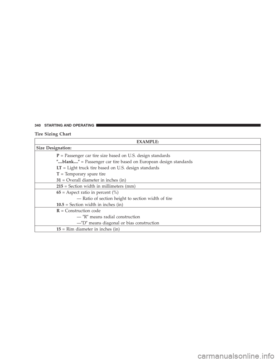
Tire Sizing Chart
EXAMPLE:
Size Designation:
P= Passenger car tire size based on U.S. design standards
�....blank....�= Passenger car tire based on European design standards
LT= Light truck tire based on U.S. design standards
T= Temporary spare tire
31= Overall diameter in inches (in)
215= Section width in millimeters (mm)
65= Aspect ratio in percent (%)
— Ratio of section height to section width of tire
10.5= Section width in inches (in)
R= Construction code
—�R�means radial construction
—�D�means diagonal or bias construction
15= Rim diameter in inches (in)
340 STARTING AND OPERATING