2009 CHEVROLET EXPRESS CARGO VAN radio
[x] Cancel search: radioPage 201 of 408
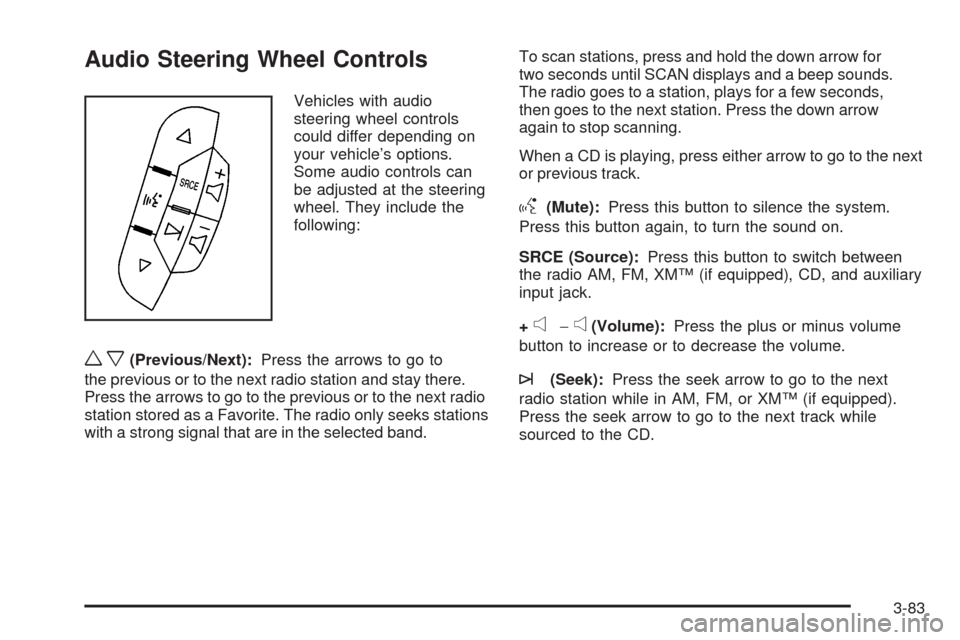
Audio Steering Wheel Controls
Vehicles with audio
steering wheel controls
could differ depending on
your vehicle’s options.
Some audio controls can
be adjusted at the steering
wheel. They include the
following:
wx(Previous/Next):Press the arrows to go to
the previous or to the next radio station and stay there.
Press the arrows to go to the previous or to the next radio
station stored as a Favorite. The radio only seeks stations
with a strong signal that are in the selected band.To scan stations, press and hold the down arrow for
two seconds until SCAN displays and a beep sounds.
The radio goes to a station, plays for a few seconds,
then goes to the next station. Press the down arrow
again to stop scanning.
When a CD is playing, press either arrow to go to the next
or previous track.
g(Mute):Press this button to silence the system.
Press this button again, to turn the sound on.
SRCE (Source):Press this button to switch between
the radio AM, FM, XM™ (if equipped), CD, and auxiliary
input jack.
+
e−e(Volume):Press the plus or minus volume
button to increase or to decrease the volume.
¨(Seek):Press the seek arrow to go to the next
radio station while in AM, FM, or XM™ (if equipped).
Press the seek arrow to go to the next track while
sourced to the CD.
3-83
Page 202 of 408
Radio Reception
Frequency interference and static can occur during
normal radio reception if items such as cell phone
chargers, vehicle convenience accessories, and external
electronic devices are plugged into the accessory power
outlet. If there is interference or static, unplug the item
from the accessory power outlet.
AM
The range for most AM stations is greater than for FM,
especially at night. The longer range can cause station
frequencies to interfere with each other. For better radio
reception, most AM radio stations boost the power levels
during the day, and then reduce these levels during the
night. Static can also occur when things like storms and
power lines interfere with radio reception. When this
happens, try reducing the treble on your radio.
FM Stereo
FM stereo gives the best sound, but FM signals reach
only about 10 to 40 miles (16 to 65 km). Tall buildings or
hills can interfere with FM signals, causing the sound
to fade in and out.
Cellular Phone Usage
Cellular phone usage may cause interference with the
vehicle’s radio. This interference may occur when making
or receiving phone calls, charging the phone’s battery,
or simply having the phone on. This interference causes
an increased level of static while listening to the radio.
If static is received while listening to the radio, unplug the
cellular phone and turn it off.
Fixed Mast Antenna
The fixed mast antenna can withstand most car washes
without being damaged as long as it is securely attached
to the base. If the mast becomes slightly bent, straighten
it out by hand. If the mast is badly bent, replace it.
Occasionally check to make sure the antenna is
tightened to its base. If tightening is required, tighten
by hand.
3-84
Page 285 of 408
Notice:If you leave the radio or other accessories
on during the jump starting procedure, they could
be damaged. The repairs would not be covered by
the warranty. Always turn off the radio and other
accessories when jump starting the vehicle.
3. Turn off the ignition on both vehicles. Unplug
unnecessary accessories plugged into the cigarette
lighter or the accessory power outlet. Turn off
the radio and all lamps that are not needed.
This will avoid sparks and help save both
batteries. And it could save the radio!
4. Open the hoods and locate the positive (+) and
negative (−) terminal locations of the other vehicle.
Your vehicle has a remote positive (+) jump
starting terminal and a remote negative (−) jump
starting terminal. You should always use these
remote terminals instead of the terminals on the
battery.The remote positive (+) terminal is located
behind a red plastic cover near the engine accessory
drive bracket on the driver’s side of the engine
compartment, below the alternator. To uncover
the remote positive (+) terminal, open the red
plastic cover.
The remote negative (−) terminal is located on
the engine drive bracket on all V8 engines and is
marked GND (Ground).
On V6 engines the remote negative (−) terminal is
located on a tab attached to the engine accessory
drive bracket and is marked GND (Ground).
5-41
Page 308 of 408
Tire Pressure Monitor System
The Tire Pressure Monitor System (TPMS) uses radio
and sensor technology to check tire pressure levels.
The TPMS sensors monitor the air pressure in
your vehicle’s tires and transmit tire pressure
readings to a receiver located in the vehicle.
Each tire, including the spare (if provided), should be
checked monthly when cold and inflated to the inflation
pressure recommended by the vehicle manufacturer
on the vehicle placard or tire inflation pressure label.
(If your vehicle has tires of a different size than the
size indicated on the vehicle placard or tire inflation
pressure label, you should determine the proper
tire inflation pressure for those tires.)
As an added safety feature, your vehicle has been
equipped with a tire pressure monitoring system (TPMS)
that illuminates a low tire pressure telltale when one
or more of your tires is significantly under-inflated.
Accordingly, when the low tire pressure telltale
illuminates, you should stop and check your tires
as soon as possible, and inflate them to the proper
pressure. Driving on a significantly under-inflated
tire causes the tire to overheat and can lead to tire
failure. Under-inflation also reduces fuel efficiency and
tire tread life, and may affect the vehicle’s handling
and stopping ability.Please note that the TPMS is not a substitute for proper
tire maintenance, and it is the driver’s responsibility to
maintain correct tire pressure, even if under-inflation
has not reached the level to trigger illumination of
the TPMS low tire pressure telltale.
Your vehicle has also been equipped with a TPMS
malfunction indicator to indicate when the system is
not operating properly. The TPMS malfunction indicator
is combined with the low tire pressure telltale. When the
system detects a malfunction, the telltale will flash for
approximately one minute and then remain continuously
illuminated. This sequence will continue upon
subsequent vehicle start-ups as long as the malfunction
exists.
When the malfunction indicator is illuminated, the
system may not be able to detect or signal low tire
pressure as intended. TPMS malfunctions may occur
for a variety of reasons, including the installation of
replacement or alternate tires or wheels on the vehicle
that prevent the TPMS from functioning properly. Always
check the TPMS malfunction telltale after replacing one
or more tires or wheels on your vehicle to ensure that
the replacement or alternate tires and wheels allow the
TPMS to continue to function properly.
SeeTire Pressure Monitor Operation on page 5-65for
additional information.
5-64
Page 309 of 408
Federal Communications
Commission (FCC) and
Industry and Science Canada
The Tire Pressure Monitor System (TPMS) operates
on a radio frequency and complies with Part 15 of
the FCC Rules. Operation is subject to the following
two conditions:
1. This device may not cause harmful interference.
2. This device must accept any interference received,
including interference that may cause undesired
operation.
The TPMS operates on a radio frequency and complies
with RSS-210 of Industry and Science Canada.
Operation is subject to the following two conditions:
1. This device may not cause interference.
2. This device must accept any interference received,
including interference that may cause undesired
operation of the device.
Changes or modifications to this system by other than
an authorized service facility could void authorization to
use this equipment.
Tire Pressure Monitor Operation
The Tire Pressure Monitor System (TPMS), if your
vehicle has this feature, is designed to warn the driver
when a low tire pressure condition exists. TPMS sensors
are mounted onto each tire and wheel assembly,
excluding the spare tire and wheel assembly. The TPMS
sensors monitor the air pressure in the vehicle’s tires and
transmits the tire pressure readings to a receiver located
in the vehicle.
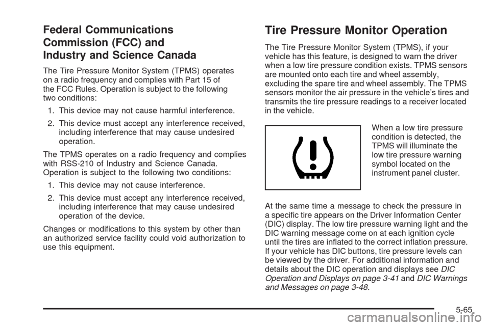
When a low tire pressure
condition is detected, the
TPMS will illuminate the
low tire pressure warning
symbol located on the
instrument panel cluster.
At the same time a message to check the pressure in
a specific tire appears on the Driver Information Center
(DIC) display. The low tire pressure warning light and the
DIC warning message come on at each ignition cycle
until the tires are inflated to the correct inflation pressure.
If your vehicle has DIC buttons, tire pressure levels can
be viewed by the driver. For additional information and
details about the DIC operation and displays seeDIC
Operation and Displays on page 3-41andDIC Warnings
and Messages on page 3-48.
5-65
Page 311 of 408
•One or more TPMS sensors are missing or
damaged. The DIC message and the TPMS
malfunction light should go off when the TPMS
sensors are installed and the sensor matching
process is performed successfully. See your
dealer/retailer for service.
•Replacement tires or wheels do not match your
vehicle’s original equipment tires or wheels. Tires
and wheels other than those recommended for your
vehicle could prevent the TPMS from functioning
properly. SeeBuying New Tires on page 5-72.
•Operating electronic devices or being near facilities
using radio wave frequencies similar to the TPMS
could cause the TPMS sensors to malfunction.
If the TPMS is not functioning it cannot detect or
signal a low tire condition. See your dealer/retailer for
service if the TPMS malfunction light and DIC message
comes on and stays on.
TPMS Sensor Matching Process
Each TPMS sensor has a unique identification code.
Any time you rotate your vehicle’s tires or replace one
or more of the TPMS sensors, the identification codes
will need to be matched to the new tire/wheel position.
The sensors are matched to the tire/wheel positions in
the following order: driver side front tire, passenger side
front tire, passenger side rear tire, and driver side rear tire
using a TPMS diagnostic tool. See your dealer/retailer for
service.
The TPMS sensors can also be matched to each
tire/wheel position by increasing or decreasing the tire’s
air pressure. If increasing the tire’s air pressure, do not
exceed the maximum inflation pressure indicated on the
tire’s sidewall.
To decrease air-pressure out of a tire you can use the
pointed end of the valve cap, a pencil-style air pressure
gage, or a key.
You have two minutes to match the first tire/wheel
position, and five minutes overall to match all four
tire/wheel positions. If it takes longer than two minutes,
to match the first tire and wheel, or more than
five minutes to match all four tire and wheel positions
the matching process stops and you need to start over.
5-67
Page 377 of 408
Customer Assistance and Information...............7-2
Customer Satisfaction Procedure......................7-2
Online Owner Center......................................7-5
Customer Assistance for Text Telephone
(TTY) Users...............................................7-6
Customer Assistance Offices............................7-6
GM Mobility Reimbursement Program................7-7
Roadside Assistance Program..........................7-7
Scheduling Service Appointments....................7-10
Courtesy Transportation.................................7-10
Collision Damage Repair................................7-12Reporting Safety Defects................................7-15
Reporting Safety Defects to the
United States Government..........................7-15
Reporting Safety Defects to the Canadian
Government..............................................7-15
Reporting Safety Defects to
General Motors.........................................7-16
Service Publications Ordering Information.........7-16
Vehicle Data Recording and Privacy................7-18
Event Data Recorders...................................7-18
OnStar
®......................................................7-19
Navigation System........................................7-19
Radio Frequency Identification (RFID)..............7-19
Section 7 Customer Assistance Information
7-1
Page 394 of 408
Vehicle Data Recording and
Privacy
Your GM vehicle has a number of sophisticated
computers that record information about the vehicle’s
performance and how it is driven. For example, your
vehicle uses computer modules to monitor and control
engine and transmission performance, to monitor the
conditions for airbag deployment and deploy airbags in a
crash and, if so equipped, to provide antilock braking to
help the driver control the vehicle. These modules may
store data to help your dealer/retailer technician service
your vehicle. Some modules may also store data about
how you operate the vehicle, such as rate of fuel
consumption or average speed. These modules may also
retain the owner’s personal preferences, such as radio
pre-sets, seat positions, and temperature settings.
Event Data Recorders
This vehicle has an Event Data Recorder (EDR). The
main purpose of an EDR is to record, in certain crash or
near crash-like situations, such as an airbag deployment
or hitting a road obstacle, data that will assist in
understanding how a vehicle’s systems performed.
The EDR is designed to record data related to vehicle
dynamics and safety systems for a short period of time,
typically 30 seconds or less. The EDR in this vehicle
is designed to record such data as:
•How various systems in your vehicle were operating
•Whether or not the driver and passenger safety
belts were buckled/fastened
•How far, if at all, the driver was pressing the
accelerator and/or brake pedal
•How fast the vehicle was traveling
This data can help provide a better understanding of the
circumstances in which crashes and injuries occur.
7-18