Page 941 of 1903

Downloaded from www.Manualslib.com manuals search engine ON-VEHICLE SERVICE
Exhaust Pipe Assembly
Removal & Installation - 1.6L & 1.8L & 2.0L
WARNING!
The normal operating temperature of the exhaust system is very high. Therefore, never work around, or attempt
to service any part of the exhaust system until it has cooled. Special care should be taken when working near
the catalytic converter. The temperature of the converter rises to a high level after a short period of engine oper-
ating time.
1. Raise and support the vehicle.
2. Remove the catalytic converter to exhaust manifoldbolts (1).
(Tighten: Exhaust manifold flange bolts to 49 ± 5
N·m)
3. Remove all the support isolators.
4. Remove the exhaust pipe assembly.
Removal & Installation - 2.4L
WARNING!
The normal operating temperature of the exhaust system is very high. Therefore, never work around, or attempt
to service any part of the exhaust system until it has cooled. Special care should be taken when working near
the catalytic converter. The temperature of the converter rises to a high level after a short period of engine oper-
ating time.
1. Raise and support the vehicle.
2. Remove the catalytic converter to exhaust manifold bolts (1).
(Tighten: Exhaust manifold flange bolts to 49 ± 5
N·m)
3. Remove all the support isolators.
4. Remove the exhaust pipe assembly.
LTSM070005
LTSM020189
07
07–5Chery Automobile Co., Ltd.
Page 942 of 1903

Downloaded from www.Manualslib.com manuals search engine Muffler
Removal & Installation
WARNING!
The normal operating temperature of the exhaust system is very high. Therefore, never work around, or attempt
to service any part of the exhaust system until it has cooled. Special care should be taken when working near
the catalytic converter. The temperature of the converter rises to a high level after a short period of engine oper-
ating time.
1. Raise and support the vehicle.
2. Remove the muffler mounting nuts (1).(Tighten: Muffler mounting nuts to 50 N·m)
3. Remove the support isolators (2).
4. Remove the muffler.
5. Clean the ends of the pipes and the muffler to ensure proper mating of all parts. Discard broken or worn isola- tors, rusted or overused clamps, supports, and attaching parts.
6. Installation is in the reverse order of removal.
Catalytic Converter
Description
The catalytic converter is attached to the exhaust manifold using fasteners and a gasket for sealing.
The catalytic converter plays a major role in the emission control system. The catalytic converter operates as a gas
reactor. Its catalytic function is to speed the heat-producing chemical reaction of components in the exhaust gases in
order to reduce air pollutants.
Operation
Catalyst operation is dependent on its ability to store and release the oxygen needed to complete the emissions-
reducing chemical reactions. As a catalyst deteriorates, its ability to store oxygen is reduced. Since the catalyst’s
ability to store oxygen is somewhat related to proper operation, oxygen storage can be used as an indicator of cat-
alyst performance.
CAUTION:
Unleaded gasoline must be used in order to avoid damaging the catalyst core.
ON-VEHICLE SERVICE
LTSM070002
07–6Chery Automobile Co., Ltd.
Page 943 of 1903
Downloaded from www.Manualslib.com manuals search engine Removal & Installation
WARNING!
The normal operating temperature of the exhaust system is very high. Therefore, never work around or attempt
to service any part of the exhaust system until it has cooled. Special care should be taken when working near
the catalytic converter. The temperature of the converter rises to a high level after a short period of engine oper-
ating time.
1. Disconnect the negative battery cable.
2. Raise and support the vehicle.
3. Remove the catalytic converter mounting nuts (1)and gaskets.
(Tighten: Catalytic converter mounting nuts to 50
N·m)
4. Remove the catalytic converter.
5. Clean the ends of the pipes to ensure proper mat- ing of all parts. Discard broken or worn isolators,
rusted or overused clamps, supports, and attaching
parts.
6. Installation is in the reverse order of removal.
ON-VEHICLE SERVICE
LTSM07000107
07–7Chery Automobile Co., Ltd.
Page 1081 of 1903
Downloaded from www.Manualslib.com manuals search engine 26. Remove the front engine mount bolts (1).(Tighten: Front mount bolts to 60 N·m)
27. Remove the rear engine mount bolts (1) and the rear engine mount bracket bolt (2).
(Tighten: Rear mount bolts to 40 N·m)
28. Remove the transaxle mount bolts. (Tighten: Transaxle mount bolts to 40 N·m)
29. Separate the transaxle from the engine and remove the transaxle from the vehicle.
WARNING!
Use a suitable jack to support the transaxle during removal.
30. Installation is in the reverse order of removal.
ON-VEHICLE SERVICE
BESM080035
LTSM020188
08–138Chery Automobile Co., Ltd.
Page 1083 of 1903
Downloaded from www.Manualslib.com manuals search engine WARNING!
The gearshift lever must be shifted to gear P while adding transaxle fluid.
Automatic Shifter Selector
Removal & Installation
1. Raise and support the vehicle.
2. Disconnect the negative battery cable.
3. Remove the air cleaner and air duct transaxle assembly.
4. Remove the base mounting (1) of the air cleanertransaxle assembly.
5. Depress the clip then remove the shift cable (1) from the transaxle gearshift switch and remove the
shift cable clamp (2).
6. Remove the gearshift knob (1).
7. Remove the gearshift cover (2) from the lower console.
8. Apply the parking brake (apply the parking brake handle to clear lower console during removal).
9. Remove the lower console (See Lower Console Removal & Installation in Section 15 Body & Accessories).
ON-VEHICLE SERVICE
BESM080038
LTSM080186
BESM080049
08–140Chery Automobile Co., Ltd.
Page 1185 of 1903

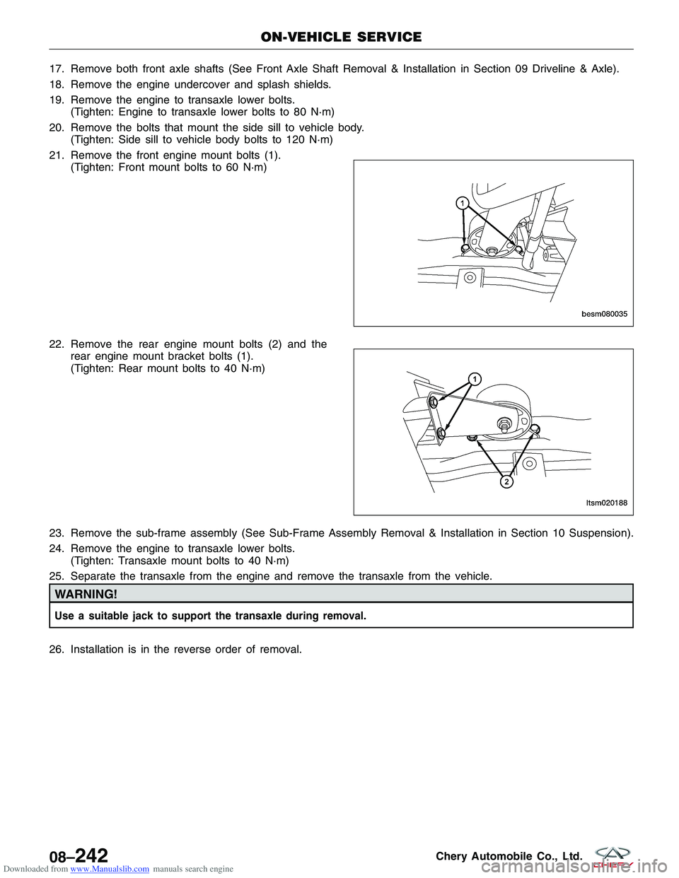
Downloaded from www.Manualslib.com manuals search engine 17. Remove both front axle shafts (See Front Axle Shaft Removal & Installation in Section 09 Driveline & Axle).
18. Remove the engine undercover and splash shields.
19. Remove the engine to transaxle lower bolts.(Tighten: Engine to transaxle lower bolts to 80 N·m)
20. Remove the bolts that mount the side sill to vehicle body. (Tighten: Side sill to vehicle body bolts to 120 N·m)
21. Remove the front engine mount bolts (1). (Tighten: Front mount bolts to 60 N·m)
22. Remove the rear engine mount bolts (2) and the rear engine mount bracket bolts (1).
(Tighten: Rear mount bolts to 40 N·m)
23. Remove the sub-frame assembly (See Sub-Frame Assembly Removal & Installation in Section 10 Suspension).
24. Remove the engine to transaxle lower bolts. (Tighten: Transaxle mount bolts to 40 N·m)
25. Separate the transaxle from the engine and remove the transaxle from the vehicle.
WARNING!
Use a suitable jack to support the transaxle during removal.
26. Installation is in the reverse order of removal.
ON-VEHICLE SERVICE
BESM080035
LTSM020188
08–242Chery Automobile Co., Ltd.
Page 1206 of 1903
Downloaded from www.Manualslib.com manuals search engine 20. Remove the rear engine mount bolts (2) and therear engine mount bracket bolts (1).
(Tighten: Rear mount bolts to 40 N·m)
21. Remove the sub-frame assembly (See Sub-Frame Assembly Removal & Installation in Section 10 Suspension).
22. Remove the engine to transaxle lower bolts (1). (Tighten: Transaxle mount bolts to 40 N·m)
23. Separate the transaxle from the engine and remove it from the vehicle.
WARNING!
Support the transaxle with a suitable jack while removing the transaxle.
24. Installation is in the reverse order of removal.
Installation Notes:
•Refill 2.2L transaxle fluid through the fill hole (1)
until the fluid starts to leak from the fill hole.
• After installation, check for any fluid leakage and
verify the transaxle fluid level is correct.
ON-VEHICLE SERVICE
LTSM020188
VISM080002
LTSM080189
08
08–263Chery Automobile Co., Ltd.
Page 1305 of 1903

Downloaded from www.Manualslib.com manuals search engine WARNING!
Do not remove the strut rod nut while the strut assembly is installed in the vehicle, or before the coil spring is
compressed with a spring compressor. The spring is held under high pressure and must be compressed before
the strut rod nut can be removed.
CAUTION:
At no time when servicing a vehicle can a sheet metal screw, bolt, or other metal fastener be
installed in the shock tower to replace the original plastic clamp. It may come in contact with the
strut or coil spring.
CAUTION:
The wheel bearing will be damaged if the vehicle is rolled with the axle shaft hub nut loose.
Operation
The front suspension utilizes a MacPherson strut system. This suspension system incorporates a strut assembly that
takes the place of the upper arm and ball joint. The strut performs the function of a shock absorber and is encom-
passed by a coil spring.
Specifications
Torque Specifications
DESCRIPTIONTORQUE (N·m)
Connecting Rod And Front Stabilizer Bar 40 - 50
Connect The Right And Left Assembly Of Front Drive
Shaft With Brake Disc 260 - 270
Control Arm And Sub-Frame 170 - 190
Connect Intermediate Propeller Shaft With Vehicle Body 58 - 68
Connecting Rod With Lower Suspension Lever 40 - 50
Connect Control Arm Knuckle Pin With Knuckle
Assembly 110 - 130
Connect Control Arm Knuckle Pin With Control Arm 140 - 160
Front Connecting Rod And Front Shock Absorber 40 - 50
Front Axle Shaft Nut 135
Fix Stabilizer Bar Clamp To Sub-Frame 22 - 28
Front Shock Absorber and Coil Spring 100 - 120
Front Suspension Strut And Vehicle Body 45 - 55
Front Suspension And Bracket 75 - 85
Insert From The Lower Part Of Sub-Frame, And The
Bolt Is On The Suspension. The Middle Part Shall Be
Clamped To The Main Longitudinal Beam Of Engine 110 - 130
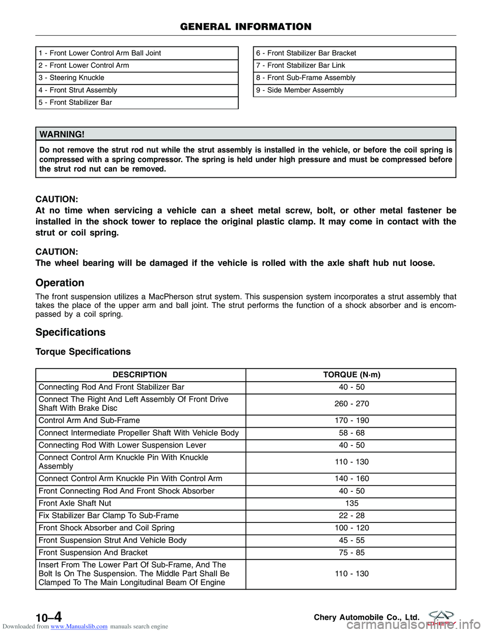
1 - Front Lower Control Arm Ball Joint
2 - Front Lower Control Arm
3 - Steering Knuckle
4 - Front Strut Assembly
5 - Front Stabilizer Bar6 - Front Stabilizer Bar Bracket
7 - Front Stabilizer Bar Link
8 - Front Sub-Frame Assembly
9 - Side Member Assembly
GENERAL INFORMATION
LTSM100008
10–4Chery Automobile Co., Ltd.