2009 CHERY TIGGO brake rotor
[x] Cancel search: brake rotorPage 1418 of 1903
Downloaded from www.Manualslib.com manuals search engine Rotor Minimum Thickness
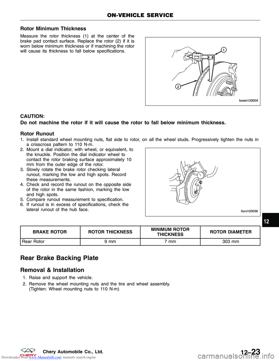
Measure the rotor thickness (1) at the center of the
brake pad contact surface. Replace the rotor (2) if it is
worn below minimum thickness or if machining the rotor
will cause its thickness to fall below specifications.
CAUTION:
Do not machine the rotor if it will cause the rotor to fall below minimum thickness.
Rotor Runout
1. Install standard wheel mounting nuts, flat side to rotor, on all the wheel studs. Progressively tighten the nuts ina crisscross pattern to 110 N·m.
2. Mount a dial indicator, with wheel, or equivalent, to the knuckle. Position the dial indicator wheel to
contact the rotor braking surface approximately 10
mm from the outer edge of the rotor.
3. Slowly rotate the brake rotor checking lateral runout, marking the low and high spots. Record
these measurements.
4. Check and record the runout on the opposite side of the rotor in the same fashion, marking the low
and high spots.
5. Compare runout measurement to specification.
6. If runout is in excess of specifications, check the lateral runout of the hub face.
BRAKE ROTOR ROTOR THICKNESS MINIMUM ROTOR
THICKNESS ROTOR DIAMETER
Rear Rotor 9 mm7 mm303 mm
Rear Brake Backing Plate
Removal & Installation
1. Raise and support the vehicle.
2. Remove the wheel mounting nuts and the tire and wheel assembly.
(Tighten: Wheel mounting nuts to 110 N·m)
ON-VEHICLE SERVICE
BESM120004
LTSM120036
12
12–23Chery Automobile Co., Ltd.
Page 1419 of 1903
Downloaded from www.Manualslib.com manuals search engine 3. Remove the rear brake caliper (See Rear BrakeCaliper Removal & Installation in Section 12
Brake).
4. Remove the rear brake rotor (See Rear Brake Rotor Removal & Installation in Section 12 Brake).
5. Remove the rear hub and bearing (See Rear Hub And Bearing Removal & Installation in Section 09
Driveline & Axle).
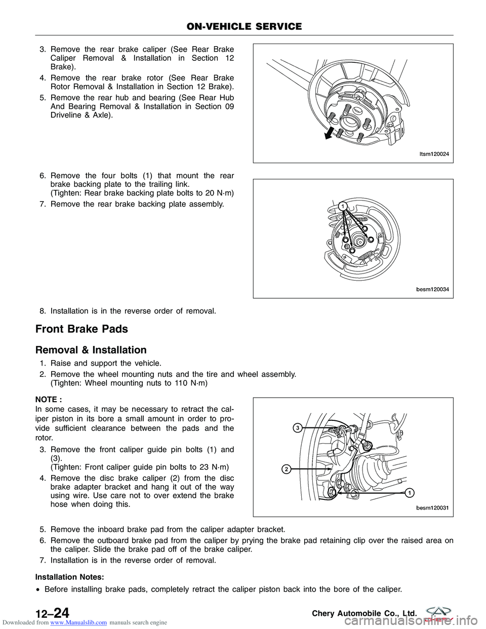
6. Remove the four bolts (1) that mount the rear brake backing plate to the trailing link.
(Tighten: Rear brake backing plate bolts to 20 N·m)
7. Remove the rear brake backing plate assembly.
8. Installation is in the reverse order of removal.
Front Brake Pads
Removal & Installation
1. Raise and support the vehicle.
2. Remove the wheel mounting nuts and the tire and wheel assembly. (Tighten: Wheel mounting nuts to 110 N·m)
NOTE :
In some cases, it may be necessary to retract the cal-
iper piston in its bore a small amount in order to pro-
vide sufficient clearance between the pads and the
rotor. 3. Remove the front caliper guide pin bolts (1) and (3).
(Tighten: Front caliper guide pin bolts to 23 N·m)
4. Remove the disc brake caliper (2) from the disc brake adapter bracket and hang it out of the way
using wire. Use care not to over extend the brake
hose when doing this.
5. Remove the inboard brake pad from the caliper adapter bracket.
6. Remove the outboard brake pad from the caliper by prying the brake pad retaining clip over the raised area on the caliper. Slide the brake pad off of the brake caliper.
7. Installation is in the reverse order of removal.
Installation Notes:
• Before installing brake pads, completely retract the caliper piston back into the bore of the caliper.
ON-VEHICLE SERVICE
LTSM120024
BESM120034
BESM120031
12–24Chery Automobile Co., Ltd.
Page 1420 of 1903

Downloaded from www.Manualslib.com manuals search engine •After installation and before moving the vehicle, pump the brake pedal several times to set the pads to the
brake rotor.
• Check and adjust the brake fluid level in the reservoir as necessary.
• Road test the vehicle and make several stops to wear off any foreign material on the brakes and to seat the
brake pads.
• After installation and before moving the vehicle, pump the brake pedal several times to set the pads to the
brake rotor.
Inspection
Visually inspect brake pads for uneven lining wear. Also inspect for excessive lining deterioration. Check the clear-
ance between the tips of the wear indicators (if equipped) on the pads and the brake rotors. If a visual inspection
does not adequately determine the condition of the lining, a physical check will be necessary. To check the amount
of lining wear, remove the disc brake pads from the vehicle. Measure the brake pad minimum thickness. Brake pads
must be replaced when usable material on a brake pad lining measured at its thinnest point measures one millimeter
or less. Replace both disc brake pads (inboard and outboard) at each caliper. It is also necessary to replace the pads
on the opposite side of the vehicle as well as the pads failing inspection to maintain proper braking characteristics.
If the brake pad assemblies do not require replacement, be sure to reinstall the brake pads in the original position
from which they were removed.
Rear Brake Pads
Removal & Installation
1. Raise and support the vehicle.
2. Remove the wheel mounting nuts and the tire and wheel assembly.
(Tighten: Wheel mounting nuts to 110 N·m)
NOTE :
In some cases, it may be necessary to retract the caliper piston in its bore a small amount in order to provide suf-
ficient clearance between the pads and the rotor. 3. Remove the lower rear caliper guide pin bolt (2). (Tighten: Rear caliper guide pin bolt to 23 N·m)
CAUTION: When moving rear brake caliper
upward, use extreme care not to damage or
overextend the flex hose.
4. Rotate the caliper (1) upward hinging off the upper guide pin bolt. Rotate the caliper upward just
enough to allow brake pad removal.
5. Slide the rear brake pads off of the brake caliper adapter.
ON-VEHICLE SERVICE
LTSM120044
LTSM120018
12
12–25Chery Automobile Co., Ltd.
Page 1421 of 1903
Downloaded from www.Manualslib.com manuals search engine Inspection
Visually inspect brake pads for uneven lining wear. Also inspect for excessive lining deterioration. Check the clear-
ance between the tips of the wear indicators (if equipped) on the pads and the brake rotors. If a visual inspection
does not adequately determine the condition of the lining, a physical check will be necessary. To check the amount
of lining wear, remove the disc brake pads from the vehicle. Measure the brake pad minimum thickness. Brake pads
must be replaced when usable material on a brake pad lining measured at its thinnest point measures one millimeter
or less. Replace both disc brake pads (inboard and outboard) at each caliper. It is also necessary to replace the pads
on the opposite side of the vehicle as well as the pads failing inspection to maintain proper braking characteristics.
If the brake pad assemblies do not require replacement, be sure to reinstall the brake pads in the original position
from which they were removed.
ON-VEHICLE SERVICE
12–26Chery Automobile Co., Ltd.
Page 1477 of 1903
Downloaded from www.Manualslib.com manuals search engine DIAGNOSIS & TESTING
Parking Brake Warning Light
The parking brake switch is incorporated in the circuit for the red warning lamp in the dash. The switch will cause the
lamp to illuminate only when the parking brakes are applied. If the lamp remains on after parking brake release, the
switch or circuit is faulty.
Parking Brake Operation
The leading cause of improper parking brake operation, is excessive clearance between the parking brake shoes and
the shoe braking surface. Excessive clearance is a result of lining and/or drum wear, drum surface machined over-
size.
In most cases, the actual cause of an improperly functioning parking brake (too loose/too tight/won’t hold), can be
traced to a parking brake component.
Inspect the following when diagnosing a parking brake problem:
•Brake shoe wear
• Drum surface (in rear rotor) machined oversize
• Front cable not secured to lever
• Rear cable not attached to actuator
• Rear cable seized
• Parking brake lever not seated
• Parking brake lever bind
Parking Brake Adjustment
Adjust the parking brake only if the parking brake lever can be pulled up more than 3 notches without having an
adequate solid braking effect.
NOTE :
Excessive parking brake lever travel (sometimes described as a loose lever or too loose condition), could be the
result of worn brake shoes, improper brake shoe adjustment, or improperly assembled brake parts. A too loose con-
dition can also be caused by inoperative or improperly assembled parking brake components. Always confirm that the
parking brake components are assembled properly. Perform the following procedure to adjust the parking brake:
1. Verify the parking brake lever is in the released (down) position.
2. Raise and support the vehicle.
3. Remove the wheel mounting nuts and the rear tire and wheel assemblies.
4. Utilizing the access hole in the rotors, adjust the parking brake shoes.
5. Reach inside the vehicle and fully apply and release the parking brake.
6. With the parking brake lever in the fully applied (up) position, attempt to rotate the rear rotors by hand (to ensure that the parking brake shoes are working properly).
7. With the parking brake lever in the released (down) position, attempt to rotate the rear rotors by hand (to ensure that the parking brake shoes are not dragging).
8. Install both rear tire and wheel assemblies and the wheel mounting nuts. (Tighten: Wheel mounting nuts to 110 N·m)
12–82Chery Automobile Co., Ltd.
Page 1481 of 1903
Downloaded from www.Manualslib.com manuals search engine Parking Brake Shoes
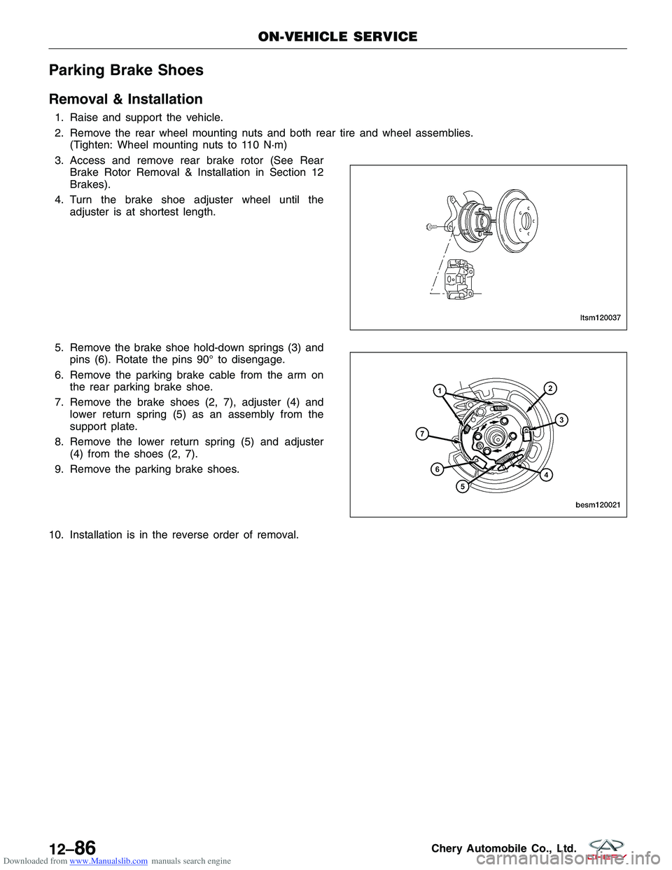
Removal & Installation
1. Raise and support the vehicle.
2. Remove the rear wheel mounting nuts and both rear tire and wheel assemblies.(Tighten: Wheel mounting nuts to 110 N·m)
3. Access and remove rear brake rotor (See Rear Brake Rotor Removal & Installation in Section 12
Brakes).
4. Turn the brake shoe adjuster wheel until the adjuster is at shortest length.
5. Remove the brake shoe hold-down springs (3) and pins (6). Rotate the pins 90° to disengage.
6. Remove the parking brake cable from the arm on the rear parking brake shoe.
7. Remove the brake shoes (2, 7), adjuster (4) and lower return spring (5) as an assembly from the
support plate.
8. Remove the lower return spring (5) and adjuster (4) from the shoes (2, 7).
9. Remove the parking brake shoes.
10. Installation is in the reverse order of removal.
ON-VEHICLE SERVICE
LTSM120037
BESM120021
12–86Chery Automobile Co., Ltd.
Page 1898 of 1903
Downloaded from www.Manualslib.com manuals search engine E
ECM Power Supply and Ground Circuit Test, 1.6L & 1.8LEngine Controls ........................... 3-28
ECM Power Supply and Ground Circuit Test, 2.0L Engine Controls ............................... 3-254
ECM Power Supply and Ground Circuit Test, 2.4L Engine Controls ............................... 3-462
EGR Control Solenoid Valve 2.4L, Evaporative Emissions .............................. 3-587
EGR Valve 2.4L, Evaporative Emissions ............3-588
Electrical Circuit Diagnosis Information .............1-15
Electrical Components, Wiring Information ..........16-9
Electrical Information ......................... 1-20
Electrical Repair, Wiring Information ...............16-8
Electrical Schematics, Vehicle Ground Distribution ....16-29
Electrical Schematics, Vehicle Power Distribution .....16-14
Electrical Troubleshooting Tools, Wiring Information ....16-6
Electrical Troubleshooting, Wiring Information ........16-5
Electronic Throttle Control Actuator, 1.6L & 1.8L Engine Controls .......................... 3-225
Electronic Throttle Control Actuator, 2.0L Engine Controls ............................... 3-439
Engine Assembly, 1.6L & 1.8L Engine Mechanical .....2-31
Engine Assembly, 2.0L Engine Mechanical ..........2-105
Engine Assembly, 2.4L Engine Mechanical ..........2-183
Engine Block, 1.6L & 1.8L Engine Mechanical ........2-50
Engine Block, 2.0L Engine Mechanical ............2-123
Engine Block, 2.4L Engine Mechanical ............2-217
Engine Control Module (ECM), 1.6L & 1.8L Engine Controls .......................... 3-226
Engine Control Module (ECM), 2.0L Engine Controls . . . 3-440
Engine Control Module (ECM), 2.4L Engine Controls . . . 3-539
Engine Coolant Temperature (ECT) Sensor, 1.6L & 1.8L Engine Controls .......................... 3-217
Engine Coolant Temperature (ECT) Sensor, 2.0L Engine Controls ............................... 3-427
Engine Coolant Temperature (ECT) Sensor, 2.4L Engine Controls ............................... 3-531
Engine Mounts, 1.6L & 1.8L Engine Mechanical ......2-29
Engine Mounts, 2.0L Engine Mechanical ...........2-103
Engine Mounts, 2.4L Engine Mechanical ...........2-181
Engine Timing Belt, 1.6L & 1.8L Engine Mechanical ....2-38
Engine Timing Belt, 2.0L Engine Mechanical ........2-112
Engine Timing Belt, 2.4L Engine Mechanical ........2-189
Engine Unit Repair, 1.6L & 1.8L Engine Mechanical ....2-50
Engine Unit Repair ,
2.0L Engine Mechanical ........2-123
Engine Unit Repair, 2.4L Engine Mechanical ........2-217
Evaporative Emissions ....................... 3-576Evaporator, System Plumbing
..................13-42
Exhaust Manifold, 1.6L & 1.8L Engine Mechanical .....2-41
Exhaust Manifold, 2.0L Engine Mechanical .........2-115
Exhaust Manifold, 2.4L Engine Mechanical .........2-200
Exhaust Pipe Assembly, Exhaust System ............7-5
Exhaust System .............................7-1
Exterior Lamps, Body Exterior .................15-178
F
F4A4 Automatic Transaxle ..................... 8-143
F4A4 Automatic Transaxle Assembly, F4A4 Automatic Transaxle ............................... 8-240
Fastener Usage, Vehicle Information ...............1-14
Fender, Body Exterior ....................... 15-199
Frame, Body Exterior ....................... 15-153
Front Axle .................................9-1
Front Axle Shaft, Front Axle .....................9-6
Front Body Structure, Body Exterior .............15-148
Front Brake Caliper, Base Brakes ...........12-18, 12-27
Front Brake Pads, Base Brakes .................12-24
Front Brake Rotor, Base Brakes .................12-21
Front Bumper, Body Exterior ..................15-166
Front Coil Spring, Front Suspension ..............10-16
Front Combination Lamp Assembly, Body Exterior . . . 15-189
Front Crankshaft Oil Seal, 1.6L & 1.8L Engine Mechanical ......................... 2-25
Front Crankshaft Oil Seal, 2.0L Engine Mechanical .....2-99
Front Crankshaft Oil Seal, 2.4L Engine Mechanical ....2-177
Front Differential ........................... 8-307
Front Door Weatherstrip, Body Exterior ...........15-231
Front Door, Body Exterior .................... 15-168
Front Fender, Body Exterior ...................15-199
Front Fog Lamp, Body Exterior ................15-192
Front Fuse and Relay Box, Vehicle Fuse Box Information ............................. 16-40
Front Hub and Bearing, Front Axle ................9-5
Front Intermediate Drive Shaft, Drive Shaft (4x4) ......9-27
Front Lower Control Arm, Front Suspension .........10-9
Front Passenger Side Airbag, Airbag System ........14-47
Front Room Lamp, Body Interior ................15-91
Front Seat Belt and Pre-Tensioner, Seat Belt System . . . 14-52
Front Seat, Body Interior ..................... 15-106
Front Stabilizer Bar Link, Front Suspension .........10-11
Front Stabilizer Bar, Front Suspension .............10-12
Front Steering Knuckle, Front Suspension ...........10-7
Front Structure, Body Exterior .................15-151
Front Strut Assembly, Front Suspension ...........10-13
INDEX
AI
AI-3
Page 1901 of 1903
Downloaded from www.Manualslib.com manuals search engine On-Vehicle Service, Interactive Torque Management (ITM)System (4x4) ............................. 9-21
On-Vehicle Service, Manual Temperature Control .....13-15
On-Vehicle Service, Parking Brake ...............12-84
On-Vehicle Service, Power Steering Pump ..........11-34
On-Vehicle Service, Rear Axle ...................9-12
On-Vehicle Service, Rear Suspension .............10-30
On-Vehicle Service, Seat Belt System .............14-52
On-Vehicle Service, Starting System ................5-7
On-Vehicle Service, Steering Column .............11-12
On-Vehicle Service, Steering Gear ...............11-21
On-Vehicle Service, Steering System ..............11-6
On-Vehicle Service, System Controls .............13-24
On-Vehicle Service, System Plumbing .............13-37
On-Vehicle Service, Transfer Case (4x4) ...........8-328
On-Vehicle Service, Wheels and Tires .............10-51
Output Gear For Reverse Gear, 5-Speed Manual Transaxle ......................... 8-296
Output Shaft, 5-Speed Manual Transaxle ...........8-287
Outside Mirror, Body Exterior ..................15-214
Oxygen Sensor, 1.6L & 1.8L Engine Controls .......3-218
Oxygen Sensor, 2.0L Engine Controls .............3-428
Oxygen Sensor, 2.4L Engine Controls .............3-533
P
Paint Codes, Body Exterior ...................15-215
Paint, Body Exterior ........................ 15-215
Parking Brake ............................. 12-79
Parking Brake Cable, Parking Brake ..............12-85
Parking Brake Lever, Parking Brake ..............12-84
Parking Brake Shoes, Parking Brake ..............12-86
Pedal Pad, Body Interior ...................... 15-14
Pistons, 1.6L & 1.8L Engine Mechanical ............2-53
Pistons, 2.0L Engine Mechanical ................2-126
Pistons, 2.4L Engine Mechanical ................2-221
Positive Battery Cable, Starting System .............5-8
Power Brake Booster - LHD, Base Brakes ..........12-14
Power Brake Booster - RHD, Base Brakes ..........12-16
Power Fuse Box, Vehicle Fuse Box Information ......16-38
Power Outlet, Body Interior .................... 15-93
Power Steering Filling and Flushing, Steering System . . . 11-6
Power Steering Fluid Reservoir, Power Steering Pump ........................... 11-36
Power Steering Pressure and Return Lines - 1.6L & 1.8L & 2.0L, Power Steering Pump . . 11-37
Power Steering Pressure and Return Lines - 2.4L, Power Steering Pump ........................... 11-39
Power Steering Pump ....................... 11-31Power Steering Pump - 1.6L & 1.8L & 2.0L,
Power Steering Pump ...................... 11-34
Power Steering Pump - 2.4L, Power Steering Pump . . . 11-35
Power Window Motor, Body Interior .............15-100
Power Window Switch, Body Interior ............15-100
Power Window, Body Interior ..................15-96
Proper Service Practices, Service Information .........1-5
R
Radiator Support, Body Exterior................15-216
Radiator Support, Body Exterior ...................216
Radiator, Cooling System ...................... 6-17
Radio, Body Interior ......................... 15-8
Rear Axle ..................................9-8
Rear Axle Assembly (4x4), Rear Axle ..............9-13
Rear Brake Backing Plate, Base Brakes ............12-23
Rear Brake Caliper, Base Brakes ...........12-19, 12-30
Rear Brake Pads, Base Brakes ..................12-25
Rear Brake Rotor, Base Brakes .................12-22
Rear Coil Spring, Rear Suspension ...............10-33
Rear Combination Lamp Assembly, Body Exterior ....15-190
Rear Crankshaft Oil Seal, 1.6L & 1.8L Engine Mechanical .............................. 2-27
Rear Crankshaft Oil Seal, 2.0L Engine Mechanical ....2-100
Rear Crankshaft Oil Seal, 2.4L Engine Mechanical ....2-179
Rear Door Weatherstrip, Body Exterior ...........15-232
Rear Door, Body Exterior .................... 15-173
Rear Fog Lamp, Body Exterior .................15-193
Rear Hub and Bearing, Rear Axle ................9-12
Rear Intermediate Drive Shaft, Drive Shaft (4x4) ......9-27
Rear Lower Control Arm, Rear Suspension .........10-30
Rear Seat Belt and Pre-Tensioner, Seat Belt System . . . 14-54
Rear Seats, Body Interior .................... 15-107
Rear Shock Absorber, Rear Suspension ...........10-32
Rear Stabilizer Bar Link, Rear Suspension ..........10-32
Rear Suspension ........................... 10-25
Rear Trailing Arm Assembly, Rear Suspension .......10-35
Rear Upper Control Arm, Rear Suspension .........10-31
Rear Wheel Alignment, Alignment ...............10-45
Rear Wheel Speed Sensor, Antilock Brakes .........12-78
Rear Window, Body Exterior ..................15-221
Rear Wiper Arm, Body Exterior ................15-240
Rear Wiper Motor, Body Exterior ...............15-239
Recirculation Door Actuator, System Controls .......13-24
Remote Keyless Entry (RKE) Inoperative, Body Interior ........................... 15-115
Restraints Control Module (RCM), Airbag System .....14-49
INDEX
AI-6