Page 1345 of 1903
Downloaded from www.Manualslib.com manuals search engine ON-VEHICLE SERVICE
Front Wheel Alignment
Front Wheel Alignment Specifications
NOTE :
If the vehicle has been in an accident causing the front axle components to be damaged, the damaged components
must be replaced before performing a front wheel alignment.
FRONT WHEEL ALIGNMENT
FRONT WHEEL ALIGNMENT PREFERRED SETTINGACCEPTABLE RANGE
Camber -51’+9’ to -1°51’
Caster +2°50’+3°30’ to +2°5’
Inclination +11°30’+12°15’ to +10°45’
Toe-Individual 0’+5’ to -5’
Front Axle Toe-In Adjustment
CAUTION:
Do not twist the inner tie rod steering gear boot (bellows) while turning the inner tie rod during
front toe-in adjustment. It may be necessary to remove the clamp where the boot meets the inner
tie rod.
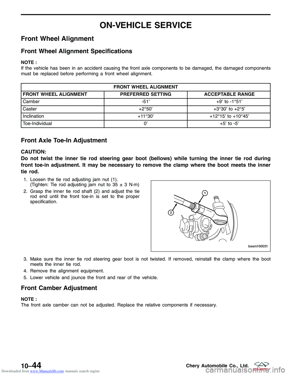
1. Loosen the tie rod adjusting jam nut (1).
(Tighten: Tie rod adjusting jam nut to 35 ± 3 N·m)
2. Grasp the inner tie rod shaft (2) and adjust the tie rod end until the front toe-in is set to the proper
specification.
3. Make sure the inner tie rod steering gear boot is not twisted. If removed, reinstall the clamp where the boot meets the inner tie rod.
4. Remove the alignment equipment.
5. Lower vehicle and jounce the front and rear of the vehicle.
Front Camber Adjustment
NOTE :
The front axle camber can not be adjusted. Replace the relative components if necessary.
BESM100031
10–44Chery Automobile Co., Ltd.
Page 1376 of 1903
Downloaded from www.Manualslib.com manuals search engine ON-VEHICLE SERVICE
Steering Gear - LHD
Removal & Installation
NOTE :
The following special tools are required to perform the repair procedure:
•CH-10002 - Ball Joint Separator
1. Siphon out as much power steering fluid as possible from the reservoir.
WARNING!
Prolonged and repeated contact with power steering fluid will damage skin. If steering fluid is spilled on your
skin, wash it off immediately with water.
2. Remove the wheel mounting nuts and wheel assemblies from both sides of the vehicle. (Tighten: Wheel mounting nuts to 110 N·m)
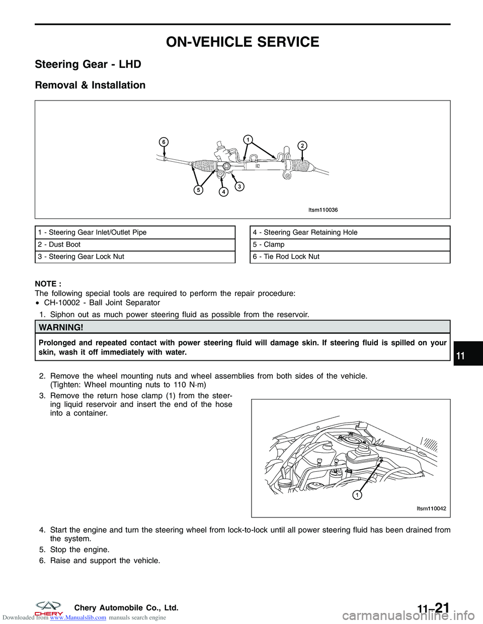
3. Remove the return hose clamp (1) from the steer- ing liquid reservoir and insert the end of the hose
into a container.
4. Start the engine and turn the steering wheel from lock-to-lock until all power steering fluid has been drained from the system.
5. Stop the engine.
6. Raise and support the vehicle.
1 - Steering Gear Inlet/Outlet Pipe
2 - Dust Boot
3 - Steering Gear Lock Nut4 - Steering Gear Retaining Hole
5 - Clamp
6 - Tie Rod Lock Nut
LTSM110036
LTSM110042
11
11 –21Chery Automobile Co., Ltd.
Page 1380 of 1903
Downloaded from www.Manualslib.com manuals search engine Steering Gear - RHD
Removal & Installation
NOTE :
The following special tool is required to perform the repair procedure:
•CH-10002 - Ball Joint Separator
1. Siphon out as much power steering fluid as possible from the reservoir.
WARNING!
Prolonged and repeated contact with power steering fluid will damage skin. If steering fluid is spilled on your
skin, wash it off immediately with water.
2. Remove the wheel mounting nuts and the wheel assemblies from both sides of the vehicle. (Tighten: Wheel mounting nuts to 110 N·m)
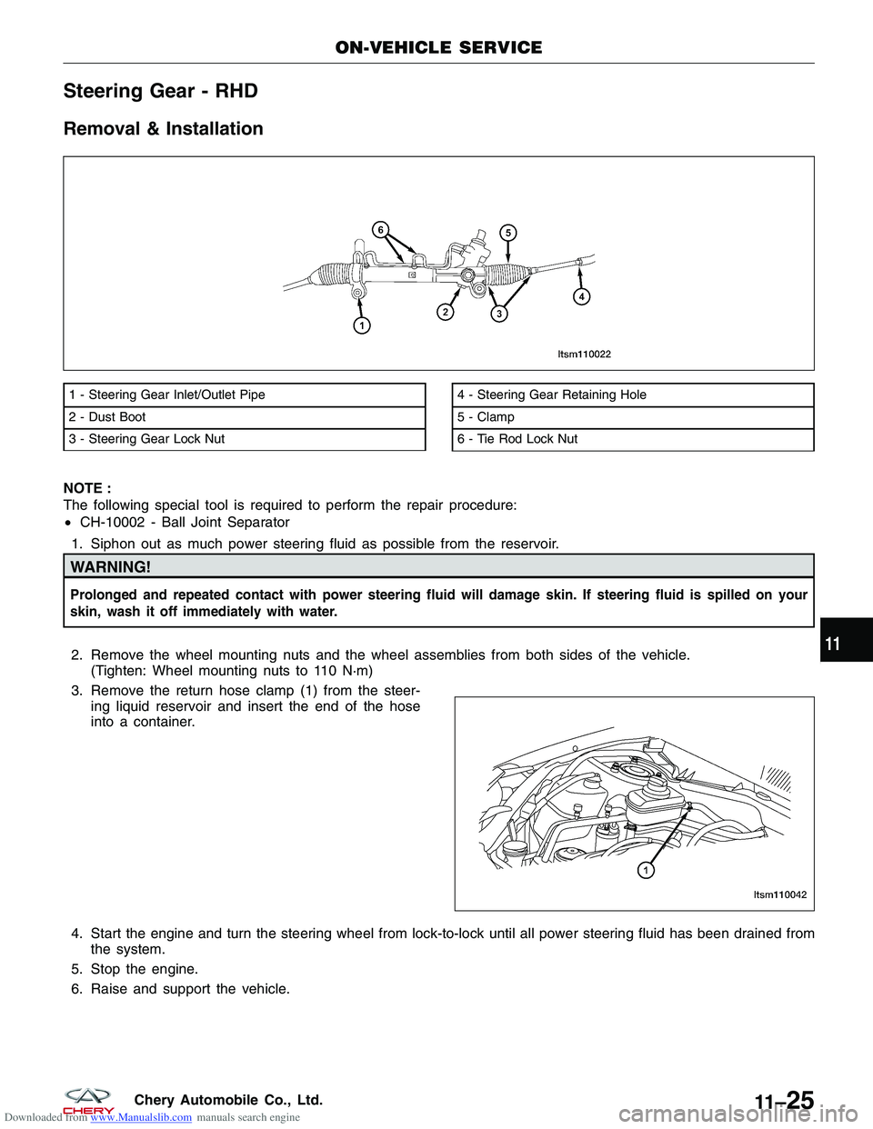
3. Remove the return hose clamp (1) from the steer- ing liquid reservoir and insert the end of the hose
into a container.
4. Start the engine and turn the steering wheel from lock-to-lock until all power steering fluid has been drained from the system.
5. Stop the engine.
6. Raise and support the vehicle.
1 - Steering Gear Inlet/Outlet Pipe
2 - Dust Boot
3 - Steering Gear Lock Nut4 - Steering Gear Retaining Hole
5 - Clamp
6 - Tie Rod Lock Nut
ON-VEHICLE SERVICE
LTSM110022
LTSM110042
11
11 –25Chery Automobile Co., Ltd.
Page 1422 of 1903
Downloaded from www.Manualslib.com manuals search engine UNIT REPAIR
Front Brake Caliper
Disassemble
Before disassembling the brake caliper, clean and inspect it.
WARNING!
•Under no condition should high pressure air ever be used to remove a piston from a caliper bore. Personal
injury could result from such a practice.
• Do not place face or hands near caliper and piston if using compressed air pressure to remove piston. Do not
use high pressure.
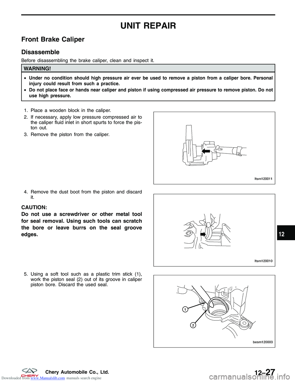
1. Place a wooden block in the caliper.
2. If necessary, apply low pressure compressed air to
the caliper fluid inlet in short spurts to force the pis-
ton out.
3. Remove the piston from the caliper.
4. Remove the dust boot from the piston and discard it.
CAUTION:
Do not use a screwdriver or other metal tool
for seal removal. Using such tools can scratch
the bore or leave burrs on the seal groove
edges.
5. Using a soft tool such as a plastic trim stick (1),work the piston seal (2) out of its groove in caliper
piston bore. Discard the used seal.
LTSM120011
LTSM120010
BESM120003
12
12–27Chery Automobile Co., Ltd.
Page 1424 of 1903
Downloaded from www.Manualslib.com manuals search engine Perform the following procedure to assemble the brake caliper:1. Lubricate the caliper piston, piston seals and piston bore with clean brake fluid.
2. Install the new piston seal into the seal groove.
NOTE :
Verify seal is fully seated into seal groove and not
twisted.
3. Install the new dust boot on the caliper piston and seat the dust boot lip into the piston groove.
4. Stretch the dust boot rearward to straighten the boot folds, then move the boot forward until the
fold snaps into place.
UNIT REPAIR
LTSM120014
LTSM120015
12
12–29Chery Automobile Co., Ltd.
Page 1425 of 1903
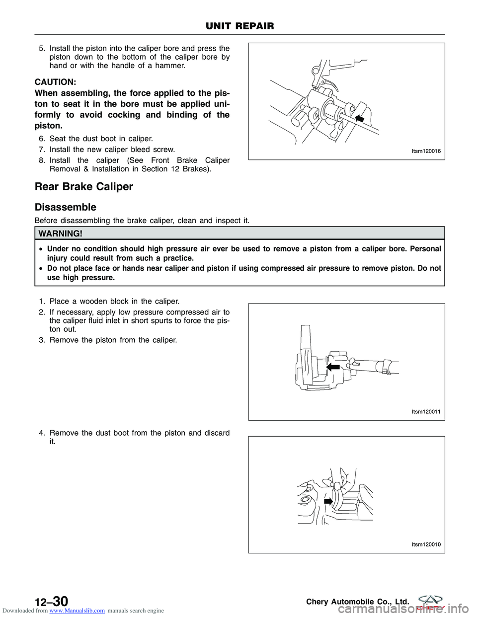
Downloaded from www.Manualslib.com manuals search engine 5. Install the piston into the caliper bore and press thepiston down to the bottom of the caliper bore by
hand or with the handle of a hammer.
CAUTION:
When assembling, the force applied to the pis-
ton to seat it in the bore must be applied uni-
formly to avoid cocking and binding of the
piston.
6. Seat the dust boot in caliper.
7. Install the new caliper bleed screw.
8. Install the caliper (See Front Brake CaliperRemoval & Installation in Section 12 Brakes).
Rear Brake Caliper
Disassemble
Before disassembling the brake caliper, clean and inspect it.
WARNING!
•Under no condition should high pressure air ever be used to remove a piston from a caliper bore. Personal
injury could result from such a practice.
• Do not place face or hands near caliper and piston if using compressed air pressure to remove piston. Do not
use high pressure.
1. Place a wooden block in the caliper.
2. If necessary, apply low pressure compressed air to
the caliper fluid inlet in short spurts to force the pis-
ton out.
3. Remove the piston from the caliper.
4. Remove the dust boot from the piston and discard it.
UNIT REPAIR
LTSM120016
LTSM120011
LTSM120010
12–30Chery Automobile Co., Ltd.
Page 1428 of 1903
Downloaded from www.Manualslib.com manuals search engine 3. Install the new dust boot on the caliper piston andseat the dust boot lip into the piston groove.
4. Stretch the dust boot rearward to straighten the boot folds, then move the boot forward until the
fold snaps into place.
5. Install the piston into the caliper bore and press the piston down to the bottom of the caliper bore by
hand or with the handle of a hammer.
CAUTION:
When assembling, the force applied to the piston to seat it in the bore must be applied uniformly
to avoid cocking and binding of the piston.
6. Seat the dust boot in caliper.
7. Install the new caliper bleed screw.
8. Install the caliper (See Front Brake Caliper Removal & Installation in Section 12 Brakes).
UNIT REPAIR
LTSM120015
LTSM120016
12
12–33Chery Automobile Co., Ltd.