Page 1257 of 1903
Downloaded from www.Manualslib.com manuals search engine 7. Install the lock pin (2).
8. Install the lock pin in the position shown in the fig-ure.
CAUTION:
After the lock pin is taped in, the axle shaft
gear and the planetary gear should operate
normally.
9. Using special tools MD-998812 (1) and MB-998819(2), install the differential front/rear bearing (3).
10. Install the driven gear of main reducing gear.
11. Apply thread sealant to the threads of all bolts.
1 - Differential Housing
2 - Lock Pin
3 - Pinion Shaft
DIFFERENTIAL UNIT REPAIR
LTSM080114
LTSM080115
LTSM080116
08–314Chery Automobile Co., Ltd.
Page 1258 of 1903
Downloaded from www.Manualslib.com manuals search engine 12. Tighten the ring gear bolts (1) in the sequenceshown in the figure.
(Tighten: Ring gear bolts to 132 N·m)
DIFFERENTIAL UNIT REPAIR
LTSM080117
08
08–315Chery Automobile Co., Ltd.
Page 1259 of 1903
Downloaded from www.Manualslib.com manuals search engine CLUTCH SYSTEM
GENERAL INFORMATION08-317
Description 08-317
Operation 08-317
Specifications 08-317
Special Tools 08-318
CLUTCH ASSEMBLY SERVICE08-319
Clutch and Pressure Plate 08-319
Removal & Installation 08-319
Clutch Pedal Height 08-321Clutch Pedal Free Travel
08-321
Clutch Master Cylinder 08-322
Description 08-322
Operation 08-322
Removal & Installation 08-322
Clutch Slave Cylinder 08-324
Removal & Installation 08-324
Bleeding Hydraulic Clutch 08-325
Operation 08-325
08–316Chery Automobile Co., Ltd.
Page 1260 of 1903

Downloaded from www.Manualslib.com manuals search engine GENERAL INFORMATION
Description
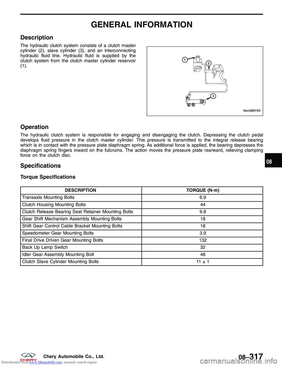
The hydraulic clutch system consists of a clutch master
cylinder (2), slave cylinder (3), and an interconnecting
hydraulic fluid line. Hydraulic fluid is supplied by the
clutch system from the clutch master cylinder reservoir
(1).
Operation
The hydraulic clutch system is responsible for engaging and disengaging the clutch. Depressing the clutch pedal
develops fluid pressure in the clutch master cylinder. This pressure is transmitted to the integral release bearing
which is in contact with the pressure plate diaphragm spring. As additional force is applied, the bearing depresses the
diaphragm spring fingers inward on the fulcrums. The action moves the pressure plate rearward, relieving clamping
force on the clutch disc.
Specifications
Torque Specifications
DESCRIPTIONTORQUE (N·m)
Transaxle Mounting Bolts 6.9
Clutch Housing Mounting Bolts 44
Clutch Release Bearing Seat Retainer Mounting Bolts 9.8
Gear Shift Mechanism Assembly Mounting Bolts 18
Shift Gear Control Cable Bracket Mounting Bolts 18
Speedometer Gear Mounting Bolts 3.9
Final Drive Driven Gear Mounting Bolts 132
Back Up Lamp Switch 32
Idler Gear Assembly Mounting Bolt 48
Clutch Slave Cylinder Mounting Bolts 11 ± 1
LTSM080194
08
08–317Chery Automobile Co., Ltd.
Page 1261 of 1903
Downloaded from www.Manualslib.com manuals search engine Special Tools
Flywheel Fixture09924 - 17810
Bearing Extractor 09917 - 58010
Input Shaft Bearing Mounting Device 09925 -98210
Clutch Pressure Plate InstallerCH-20014
GENERAL INFORMATION
08–318Chery Automobile Co., Ltd.
Page 1262 of 1903
Downloaded from www.Manualslib.com manuals search engine CLUTCH ASSEMBLY SERVICE
Clutch and Pressure Plate
Removal & Installation
1. Remove the transaxle assembly (See Transaxle Assembly Removal & Installation in Section 08 Transaxle).
2. Remove the clutch pressure plate bolts (1).(Tighten: Clutch pressure plate bolts to 25 N·m)
3. Remove the modular clutch assembly.
4. Using special tool CH-20043 (1), hold the flywheel.
5. Remove the flywheel-to-crankshaft bolts (1) and remove flywheel assembly (if necessary for resur-
facing).
(Tighten: Flywheel-to-crankshaft bolts to 75 N·m)
BESM080046
LTSM080145
BESM020058
08
08–319Chery Automobile Co., Ltd.
Page 1263 of 1903

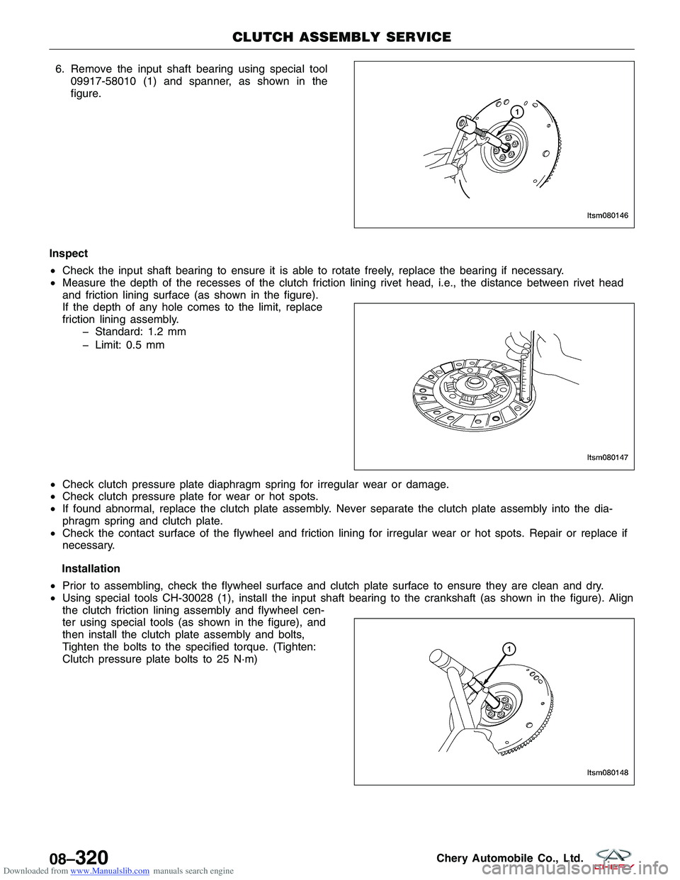
Downloaded from www.Manualslib.com manuals search engine 6. Remove the input shaft bearing using special tool09917-58010 (1) and spanner, as shown in the
figure.
Inspect
• Check the input shaft bearing to ensure it is able to rotate freely, replace the bearing if necessary.
• Measure the depth of the recesses of the clutch friction lining rivet head, i.e., the distance between rivet head
and friction lining surface (as shown in the figure).
If the depth of any hole comes to the limit, replace
friction lining assembly.
� Standard: 1.2 mm
� Limit: 0.5 mm
• Check clutch pressure plate diaphragm spring for irregular wear or damage.
• Check clutch pressure plate for wear or hot spots.
• If found abnormal, replace the clutch plate assembly. Never separate the clutch plate assembly into the dia-
phragm spring and clutch plate.
• Check the contact surface of the flywheel and friction lining for irregular wear or hot spots. Repair or replace if
necessary.
Installation
• Prior to assembling, check the flywheel surface and clutch plate surface to ensure they are clean and dry.
• Using special tools CH-30028 (1), install the input shaft bearing to the crankshaft (as shown in the figure). Align
the clutch friction lining assembly and flywheel cen-
ter using special tools (as shown in the figure), and
then install the clutch plate assembly and bolts,
Tighten the bolts to the specified torque. (Tighten:
Clutch pressure plate bolts to 25 N·m)
CLUTCH ASSEMBLY SERVICE
LTSM080146
LTSM080147
LTSM080148
08–320Chery Automobile Co., Ltd.
Page 1264 of 1903

Downloaded from www.Manualslib.com manuals search engine NOTE :
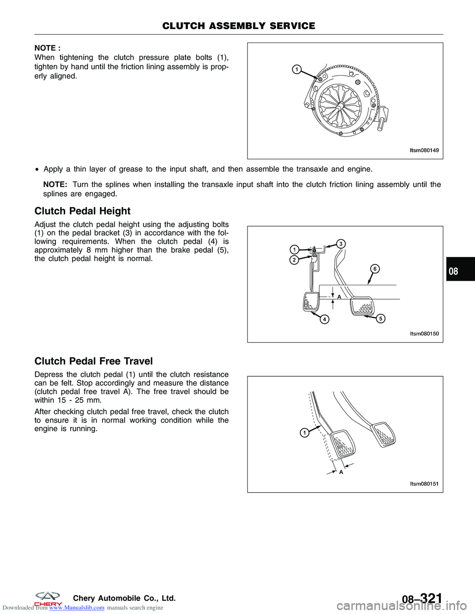
When tightening the clutch pressure plate bolts (1),
tighten by hand until the friction lining assembly is prop-
erly aligned.
•Apply a thin layer of grease to the input shaft, and then assemble the transaxle and engine.
NOTE: Turn the splines when installing the transaxle input shaft into the clutch friction lining assembly until the
splines are engaged.
Clutch Pedal Height
Adjust the clutch pedal height using the adjusting bolts
(1) on the pedal bracket (3) in accordance with the fol-
lowing requirements. When the clutch pedal (4) is
approximately 8 mm higher than the brake pedal (5),
the clutch pedal height is normal.
Clutch Pedal Free Travel
Depress the clutch pedal (1) until the clutch resistance
can be felt. Stop accordingly and measure the distance
(clutch pedal free travel A). The free travel should be
within 15 - 25 mm.
After checking clutch pedal free travel, check the clutch
to ensure it is in normal working condition while the
engine is running.
CLUTCH ASSEMBLY SERVICE
LTSM080149
LTSM080150
LTSM080151
08
08–321Chery Automobile Co., Ltd.